Published by Marek JAWORSKI, Politechnika Wrocławska, Katedra Energoelektryki
ORCID. 0000-0002-6537-050X
Abstract. The article presents issues related to choosing an overhead line route in the aspect of landscape protection. The possibility of using nonstandard supports, which task is to replace traditional electricity pylon and better integration into the surrounding landscape, was pointed out. The paper describes the advantages and disadvantages of such constructions, including compact overhead lines with special insulation cross-arms. Calculations of electric and magnetic field distributions in the vicinity of several selected supports of this kind were carried out and compared with field distributions in the vicinity of a traditional electricity pylon. The areas of the electric and magnetic components of the field for various supports of the line were determined.
Streszczenie. W referacie przedstawiono zagadnienia związane z wyborem trasy linii napowietrznych w aspekcie ochrony krajobrazu. Wskazano na możliwość zastosowania niestandardowych konstrukcji wsporczych, których zadaniem jest zastąpienie tradycyjnych słupów kratowych oraz lepsze wkomponowanie w otaczający krajobraz. Opisano wady i zalety takich konstrukcji, w tym kompaktowych linii napowietrznych ze specjalnymi poprzecznikami izolacyjnymi. Przeprowadzono obliczenia rozkładów pola elektrycznego i magnetycznego w otoczeniu kilku wybranych tego rodzaju konstrukcji wsporczych oraz porównano je z rozkładami pola w otoczeniu słupów kratowych. Określono obszary odziaływania składowej elektrycznej i magnetycznej pola dla różnych konstrukcji wsporczych linii najwyższych napięć. (Niestandardowe rozwiązania konstrukcji wsporczych linii napowietrznych wysokiego napięcia w aspekcie ochrony krajobrazu oraz oddziaływania pola elektromagnetycznego)
Keywords: overhead power lines, supports, electromagnetic fields, exposure, landscape
Słowa kluczowe: linie napowietrzne, konstrukcje wsporcze, pole elektromagnetyczne, oddziaływanie pola, krajobraz
Introduction
Over the past 20 years, Poland’s energy consumption has increased by over 23%, and its generation by just over 14%. The upward trend in energy production continued until 2018 and amounted to 165,21 TWh. In the same year, the electricity demand exceeded the value of 170 TWh for the first time [1]. In 2020, a decrease in production was recorded to 152,3 TWh while consuming 165,5 TWh of energy.
The highest voltage transmission networks (400 and 220 kV) should be prepared for connecting new generation sources, including offshore wind farms, or integration within the common European electricity market. Recently adopted regulation, the “Clean Energy for all Europeans” package [2], sets ambitious standards, defining required transmission capacity levels for cross-border exchange. Meeting these standards requires European operators to develop national networks.
The transmission network of the national transmission system operator (PSE S.A.) at present has a little over 15300 km long. Most transmission lines were built in the 1970s and 1980s. Over the past 15 years, the number of 400 kV lines increased by 63%, but at the beginning of 2021, the length of all these lines per circuit was 7822 km. Some 400 kV transmission lines can still be used for several years, but in the case of 220 kV lines (with a total length of 7380 km), this time is short. Therefore, they require urgent modernization and reconstruction to 400 kV. The need to expand the network also results from new generation sources construction, mostly renewable (RES) and so-called intervention sources.
In 2020-2030, PSE SA intends to implement one of the most ambitious investment programs in Europe in electricity transmission infrastructure. It intends to spend 14 billion PLN for this purpose, of which about 90 per cent will cover the expansion and modernization of the network. As a result of the plan’s implementation, over 3500 km of new high-voltage networks will be built over the next nine years, and over 1600 km of existing lines will be modernized [3].
Construction of overhead transmission lines in the aspect of landscape protection
The investment process, that goal is to build a transmission line, begins a thorough technical and economic study, in the course of which the basic parameters of the line are determined, which are essential for the smooth functioning of the power system: transmission capacity, voltage and line work system (single-circuit, double-circuit or multi-circuit line). The mentioned parameters are subject to a detailed analysis during the forecasting works, mainly from the economic and reliability point of view. In Poland, under the current conditions (high power transmitted over considerable distances), new transmission lines are built for 400 kV voltage. In addition, 1200 kV lines (experimental section of the line in India) and 1000 kV lines (640 km long line with 3000 MW transmission capacity in China) are being built worldwide [4].
The electromagnetic field’s impact and noise generated by an overhead line can be estimated before being built based on computer simulations. At the design stage, however, it is challenging to assess whether and to what extent the overhead line will reduce the value of the landscape, the more so because the personal feelings of individual people are subjective in this respect and often differ significantly from each other. Landscape protection is understood as a resource of visual and aesthetic values resulting from natural factors. Human activity is one of the most important tasks undertaken as part of spatial planning. According to the European Landscape Convention [5], the landscape is one of the essential elements shaping people’s quality of life, so it must be adequately protected and shaped. Aesthetic assessment of the landscape, however, is subjective and unverifiable. One person’s perception of the scenery may change depending on the time of day or atmospheric conditions. It may evolve or depend on tight to define mood swings, which was fully confirmed by the study’s findings [6]. In the visual assessment of the landscape, it is also significant to determine the assessment’s subject. Landscape can be understood as a specific view or area with defined boundaries containing many views. Despite the methodological difficulties, there have been more or less successful research attempts to evaluate geographical space aesthetics and visual attractiveness for years. One of them is the valorization of assessing Polish mesoregions’ visual attractiveness based on the assessment of the relief, surface water, and vegetation [7].
The use of overhead high voltage lines has been and remains the dominant way of transmitting electricity. Overhead transmission lines have permanently become surroundings part and a widespread element of the cultural environment, both in Poland and worldwide. Despite this universality, overhead line pylons are considered a spatial element that reduces protected areas’ landscape values to the greatest extent [6]. They are also usually the worst-rated anthropogenic element of the cultural landscape. These steel traditional electricity pylons with heights from 30 m (Y25, F series) to about 80 m (E33 series), visible from a distance of several kilometres, affect the landscape quite negatively.
This article presents several custom support structures that are already or may be used to construct new overhead power lines. In addition, the levels of electric and magnetic fields produced by such lines were also assessed and compared with the values of fields generated in the vicinity of existing overhead lines. The application of these innovative solutions may, according to the author, lead to increased social acceptance during the construction of overhead lines.
Innovative solutions for supports of overhead lines
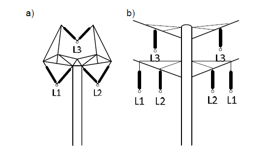
Over the past dozen or so years, many innovative support structure designs have been created to construct overhead lines. These issues became the topic of meeting representatives of 17 countries as part of the CIGRE Studies Committee. The B2-08 Working Group’s work ended with the publication in February 2010 of the CIGRE TB Technical Brochure No. 416 [8] and a 64-page annexe a few months later [9]. The publication [9] presents numerous photos of non-standard support structures erected in Denmark, Finland, France, and Iceland, which were supposed to be more visually attractive and better blend in with the surrounding landscape. Notably, the works of a Danish architectural and design company founded in 1994 by Erik Bystrup [10]. The company’s projects focus on aesthetics, functionality, economics, and ecology. In 2001, a structure called Design Pylon (Fig. 1a) designed by Bystrup received the first prize in an international competition organized by Energinet – the Danish national operator of the electricity and natural gas transmission system. In 2006, a 27-kilometre section of the overhead line was built in Denmark using 80 Design Pylon poles. The advantage of these columns was to limit visual interference in the landscape. The pole has been reduced to a few simple elements, and the pole’s height does not exceed 31.5 m.
Another solution for the double-circuit line is Eagle pylon designed by Bystrup (Fig. 1b). It uses Eagle series columns that a double-circuit 400 kV line with a length of approx. 175 km was built in Denmark in 2014, which replaced the singlecircuit line. This line now forms the mainstay of the Danish transmission network, connecting Germany with Norway and Sweden.
The Bystrup company offers a range of other support designs. These include Sky Pylon, that surface is clad with polished stainless steel [10,11]. Therefore, the pole blends into the surroundings and reflects the landscape, sky, and light. In addition, reducing the distance to 6 m between the phases enabled the pole’s design in which all phases are suspended in one horizontal plane, and its height does not exceed 29.1 m.
A few years ago, Bystrup’s research and development team designed a pylon to introduce a new transmission line industry era. The pylon is made entirely of composite materials with a pair of arms to which two 400 kV lines can be attached [10,11]. The shaft of the pole is attached to a monopole driven into the ground. This pole can be folded in place and erected in one day. Its mass constitutes about 30% of the mass of traditional steel lattice columns. It can be transported by helicopter and set up using light equipment. A 22.5 m high composite pole prototype was created in cooperation with the Danish Technical University and Aalborg University [11].
In 2011, the Royal Institute of British Architects (RIBA), Department of Energy and Climate Change (DECC), and National Grid in the United Kingdom announced a competition to design pylons of the future to replace worn steel supports [10]. The T-Pylon design developed by the Danish company Bystrup won the international competition. The pole is T-shaped and resembles a street lamp (Fig. 2a). The first constructions of these poles were erected in 2015 at the National Grid training academy in Eakring, Nottinghamshire. The approx. 35 m high T-pylon has an estimated service life of 80 years. These poles will be used to construct new overhead lines in Great Britain.
All support structures presented above are based on monopole solutions. However, the experience of Denmark and Great Britain [10] in the construction of such lines and the opinions carried out among the population prove the community’s increased acceptance of the construction of overhead lines with non-standard supports.

Thousands of kilometres of lines have been built around the world using monopole poles. These constructions also appeared in Poland, but mainly in 110 and 220 kV lines. So far, the only 400 kV line made on monopole supports is the Pasikurowice-Wrocław line with a length of about 48 km [12]. On one section, this line was built as a single-circuit 400 kV, and on the other as a three-circuit, 1×400 kV + 2×110 kV.
In European countries, compact lines are often used. Compact lines are those in which the dimensions have been minimized while maintaining all required mechanical and electrical parameters. It became possible due to eliminating traditional pylons’ cross members and their replacement with insulating cross members. Composite insulators made of glass fibre reinforced epoxy resin are most commonly used as insulating elements of the crossbeams. The first crossbar solutions using composite insulators for 400 kV were developed in 1997 by Pfisterer [13]. Pfisterer offers the third generation of insulating crossbars to construct the highest voltage compact lines, which with their parameters, ensure both electrical and mechanical safety for voltages up to 525 kV [13].
Many monopole support designs in the world are made of concrete or steel, adapted to compact lines. One of the suggestions is a pylon called (The Needle) [13].
Calculation of distributions of electric and magnetic fields in the vicinity of 400 kV lines
All the electromagnetic field distributions presented in this chapter have been prepared based on the PolE-M v.1.0.2.0 computer program developed by the article’s author. The algorithm used in the program is based on the superposition and mirroring method.
The PolE-M software enables calculations and distributions of the electric and magnetic field intensity in a cross-section perpendicular to the axis of a line equipped with up to 16 wires. In this way, the electric and magnetic field levels that may occur in the vicinity of overhead lines built using traditional and non-standard supports were checked and compared. The calculations were made for single-circuit 400 kV lines made on Y25, W33, Design Pylon (Fig.1a), and double-circuit 400 kV lines made on E33, T-Pylon (Fig.2a), Eagle Pylon (Fig. 1b), and monopole series support with metal (Fig.2b) and insulating crossbars (Fig.2c).
All calculations have been made for the most unfavourable operating conditions of the power lines. The maximum voltage, the maximum load of the line conductors, and the conductors’ minimum distance from the ground were assumed. In order to be able to compare the obtained field distributions in the vicinity of different lines, the following assumptions were made in the PolE-M program:
• conductors suspension coordinates according to the series and type of pylons,
• minimum distance from phase conductors to earth hmin = 10.0 m (the most common distance between conductors and ground when designing a 400 kV line in Poland),
• maximum line operating voltage Urmax = 420 kV (maximum value of the voltage on the lines of 400 kV,
• for single-circuit lines – steel-aluminium conductors type 2xAFL-8 525 mm2, with a diameter of 3.15 cm and a maximum load of circuit 2500 A,
• for double-circuit lines – steel-aluminium conductors type 3xAFL-8 350 mm2 with a diameter of 2.61 cm and a maximum load of circuit 2500 A,
• for double-circuit lines, the calculations were made for two different phase systems: symmetrical and opposite.
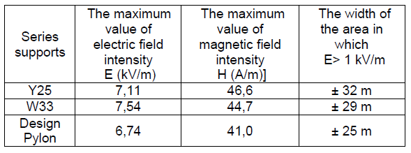
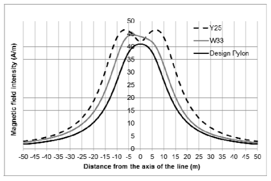
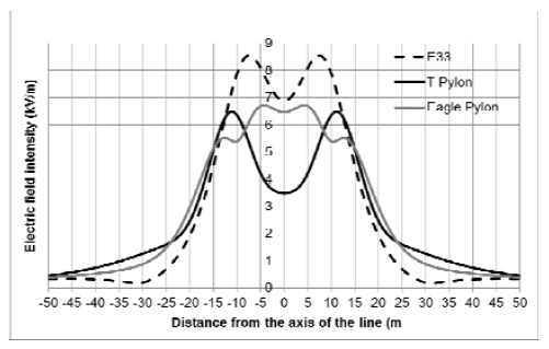
The list of calculated maximum electric and magnetic field strengths that occur in the vicinity of 400 kV single-track lines is in Tab.1, during the corresponding electric field strength distributions in Fig.3a and magnetic field – in Fig.3b. The calculated values were compared with the Polish regulations concerning the protection against the electromagnetic field in the environment.
Table 1. Calculated maximum values of electrical and magnetic field existing in the vicinity of single-circuit 400 kV line

The list of calculated maximum electric and magnetic field strengths that occur in the vicinity of 400 kV doubletrack lines is shown in Tab.2. Figure 5 shows the distribution of electric and figure 6 – magnetic field strength in the vicinity of lines made on traditional E33 series poles, T-Pylon and Eagle Pylon, with symmetrical phase arrangement.
To show that the distribution of electric and magnetic fields in the vicinity of double-track lines is influenced not only by the type of supports, resulting in a change in the geometry of the distribution of wires, but also by the arrangement of conductors, a series of calculations were carried out for double-track lines built on E33 and monopole pylons (including compact lines).
Table 2. Calculated maximum values of electrical and magnetic field existing in the vicinity of double-circuit 400 kV line


Conclusion
The advantage of using non-standard supports is the reduction of visual interference with the landscape. The calculation results show that lower electric and magnetic field strength values occur in the area located under such lines, compared to lines built using standard supporting structures. Considering the population’s fears about the impact of the electromagnetic field accompanying the operation of overhead lines and the loss of landscape values of the area through which the line route runs, it is the lines built using non-standard pylons that may gain greater social acceptance.
Lines made based on non-standard monopole pylons, including compact monopole pylons, generate in their surroundings an electric field with values not exceeding 6.3 kV/m and a magnetic field with values no more than 34.1 A/m. In the vicinity of this type of line, the area where the electric field intensity may exceed the value of 1 kV/m is very narrow and, depending on the pole’s construction, is between 43 and 39 m wide.
Based on the performed calculations, it can be concluded that the conductors’ geometry on the tower structure has a significant impact on the electric and magnetic field distribution under the overhead lines. With the same assumptions, the same values of voltage, load current, and distance of conductors from the ground for different pole structures are obtained different distributions of the two components of the electromagnetic field. As a result, the difference between the maximum values of the electric field strength under the different lines is over 2.8 kV/m. Between the maximum values of the magnetic field, strength is over almost 14 A/m.
The experience of countries such as Denmark and the United Kingdom in the construction of overhead lines using non-standard supports (T-Pylon, Design Pylon) is a positive example that such solutions are usually accepted by local communities living in areas through which such lines run. These lines can have an environmentally friendly status due to a significantly reduced impact on the landscape and lower electric and magnetic field strength values in the vicinity of lines made on a traditional electricity pylon. Innovative monopole pylons must meet the serviceability limit states specified in the standard [15]. For poles of the height H, the maximum deflection values are permissible H/50. These requirements are met by the lattice structure of the height H, which are commonly used in the construction of overhead lines in Poland. Meeting these strict strength requirements significantly limits the construction of lines based on monopole pylons in our country.
LITERATURA
[1] Energetyka, Dystrybucja i przesył, Raport PTPiREE, Poznań, (2021)
[2] Clean Energy for all Europeans, Luxembourg, Publications Office of the European Union, (2019).
[3] https://www.pse.pl/obszary-dzialalnosci/krajowy-systemelektroenergetyczny/informacje-o-systemie
[4] Rakowska A., Linie elektroenergetyczne WN i NN – światowerekordy, Przegląd Elektrotechniczny, 92 (2016), nr 10, s.1-4
[5] European Landscape Convention, Council of Europe, ETS no.176, (2000)
[6] Protecting the Irish Environment and Landscape, A critical Issue for Irish Tourism, Position Paper, ITIC, (2014)
[7] Śleszyński P., Ocena atrakcyjności wizualnej mezoregionów Polski. Znaczenie badań krajobrazowych dla zrównoważonego rozwoju, WGiSR UW, (2007), s. 697-714.
[8] Innovative solutions for overhead line supports, CIGRE TB (2010), nr 416
[9] Innovative solutions for overhead line supports, Annexe CIGRE TB (2010), nr 416
[10] https://www.powerpylons.com
[11] https://sinopa.ca/products/electricity-transmission-pylon
[12] Linia elektroenergetyczna 400 kV Pasikurowice-Wrocław zaprojektowana i zbudowana na słupach rurowych, Folder firmy KromissBis, (2011)
[14] https://sinopa.ca/obj/the-needle
[15] PN-EN 50341-2-22:2016-04, Elektroenergetyczne linie napowietrzne prądu przemiennego powyżej 1 kV – Część 2-22: Krajowe Warunki Normatywne (NNA) dla Polski
Autor: dr inż. Marek Jaworski, Politechnika Wrocławska, Katedra Energoelektryki, Wyb. Wyspiańskiego 27, 50-370 Wrocław, e-mail: marek.jaworski@pwr.edu.pl
Source & Publisher Item Identifier: PRZEGLĄD ELEKTROTECHNICZNY, ISSN 0033-2097, R. 98 NR 3/2022. doi:10.15199/48.2022.03.05
