Published by Makmur SAINI1, A. M. Shiddiq YUNUS1, Ahmad Rizal SULTAN1, Muh Ruswandi DJALAL1, Mohd. Wasir bin MUSTAFA2, Rahimuddin RAHIMUDDIN3, Ikhlas KITTA3, State Polytechnic of Ujung Pandang (1), University Teknologi Malaysia (2), Hasanuddin University (3)
Abstract. This paper introduces a comparative study for fault detection and classification on parallel transmission line using cascade forward and feed forward back propagation. Both calculations were based on discrete wavelet transform (DWT) and Clarke’s transformation. Daubechies4 mother wavelet (Db4) was applied to decompose coefficients of wavelet transforms coefficients (WTC) and wavelet energy coefficients (WEC) of high frequency signals. The coefficients were inputs for training of neural network back-propagation (BPNN). The results showed that the feed forward back propagation algorithm of Artificial Neural Network (ANN) models responded better than Cascade forward back propagation algorithm models, particularly in fault detection and classification on parallel transmission. The results showed that the proposed method for fault analysis was able to classify all the faults on the parallel transmission line rapidly and correctly.
Streszczenie. W pracy przedstawiono badanie porównawcze wykrywania i klasyfikacji uszkodzeń równoległej linii przesyłowej z wykorzystaniem propagacji kaskadowej do przodu i do tyłu. Oba obliczenia oparto na dyskretnej transformacie falkowej (DWT) i transformacji Clarke’a. Falkę macierzystą Daubechies4 (Db4) zastosowano do dekompozycji współczynników przekształceń falkowych (WTC) i współczynników energii falkowej (WEC) sygnałów wysokiej częstotliwości. Współczynniki stanowiły dane wejściowe do szkolenia propagacji wstecznej sieci neuronowej (BPNN). Wyniki pokazały, że algorytm propagacji wstecznego sprzężenia zwrotnego modeli sztucznej sieci neuronowej (ANN) zareagował lepiej niż modele algorytmu kaskadowego propagacji wstecznej, szczególnie w wykrywaniu błędów i klasyfikacji w transmisji równoległej. Wyniki pokazały, że zaproponowana metoda analizy uszkodzeń była w stanie szybko i poprawnie sklasyfikować wszystkie uszkodzenia na równoległej linii przesyłowej. Wykrywanie błędów w równoległej linii przesyłowej z wykorzystanirem transformaty Clarke’a
Keywords: Cascade and Feed forward back-propagation neural network; Clarke’s Transformation; Fault detection; Fault Classification;
Słowa kluczowe: Sieć neuronowa propagacji wstecznej i kaskadowej; Transformacja Clarke’a; Wykrywanie uszkodzeń; Falka
Introduction
Power transmission line is an essential element in power system as it can dispatch electrical energy from one place to another. However, faults are often occurred on the transmission lines due to the interferences. Moreover, short circuit at the transmission line that connected to the wind turbine for example, could damage the wind turbine generator and its power electronics device [1]. Therefore, a quick and accurate analysis is necessarily required to detect and classify the transmission lines faults to guarantee the high reliability of the power system. a parallel transmission line needs more special consideration in comparison with the single transmission line, due to the effect of mutual coupling on the parallel transmission line including a parallel transmission line that is connected with wind turbine [2]. The most advantage of the parallel transmission compared to the single line is the probability of parallel system to transmit power continuously during and after fault is better than the single line.
This paper proposed a discrete wavelet transform and back-propagation neural network using the Clarke’s transformation to detect and classify the faults on the parallel transmission line. This study proposes a new method called alpha-beta transformation that is based on the Clarke’s transformation; which is a transformation of a three-phase system into a two-phase system [3-6]. Clarke’s transformation result is then transformed into discrete wavelets transform.
Wavelet transforms have been applied in several applications of in power systems; for example on partial discharge, power system protection, power system transients, condition monitoring and transformer protection. Among aforementioned above, the power system protection become the major application area of wavelet transform in power systems [7], while the Artificial Neural Network has been widely used in power system protection [8]. In this study, a novel approach is proposed for some reliable fault detection, classification, and location. The proposed approach applied based on ANN scheme. Various types of faults were applied for classification of the faults and location [9]. There are some papers recently discussed the hybrid application of wavelet and ANN that have been applied on the variety of power system planning and power quality disturbances [10-13], estimating fault location [16], classification using Oscillographic data [14, 15], control system and state estimation [16, 17].
This study introduces a new approach for classifying faults in transmission lines using discrete wavelet transform and back-propagation neural network. The main idea of the approach is to employ wavelet coefficient detail and the wavelet energy coefficient of the currents as the input patterns to generate a simple multi-layer perception network (MLP). In addition, this study proposes the development of a new decision algorithm to be used in the protective relay for fault classification and detection. To validate this method, the applied faults were simulated using EMTDC / PSCAD software package [18]. Moreover, to obtain the significant of the study, the results of the proposed method were compared with and without wavelet transform based Clarke transformation.
Research Methodology
In this section Figure 1 shows the procedure of main steps for fault detection on transmission line using DWT and BPPN based on Clarke’s transform it also shows some tools like PSCAD/EMTDC, wavelet transform (WT) and back propagation neural network (BPNN) is used to detect and classify the faults.
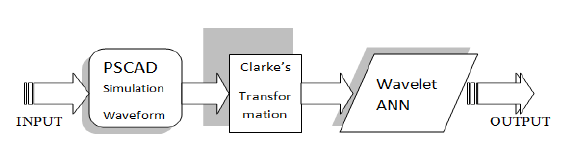
The design process of the proposed fault detection and classification algorithm for transmission line goes through the following steps:
1) Finding the input to the Clarke’s transformation and wavelet transform. The signal flow of PSCAD is then converted into m. Files (*. M)
2) Determining the data stream interference, where the signal is transformed by using the Clarke’s transformation to convert the transient signals into the signal’s basic current (Mode).
3) Input signals are analyzed by DWT for extracting the information of the transient signal in the time and the frequency domain [19].
4) Selection of a suitable BPNN topology & structure for a given application.
5) Training of BPNN and validation of the trained BPNN to check its correctness in generalization.
Results and Discussion
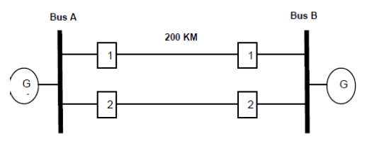
In this study, the system under study is consisted of two identical transmission lines of 200 Km length which both end side are connected to Bus A and Bus B respectively. Each bus is connected to identical generator. The system was built on a 230 kV, conducted and simulated using PSCAD/EMTD. The system under study is shown in Fig. 2. In this study faults are applied at 0.22s and last for 0.15s and system under study parameters are provided in Table 1.
Table 1. Parameters used in the model System under Study

After calculating the parameters, the training sample of the detail coefficients wavelet of S0,Sα, Sβ, Sγ, Q0, Qα, Qβ, Qγ and wavelet energy of E0 , Eα, Eβ and Eγ for various types of faults were set as input variables to create neural network. The data sets were generated by considering different operating conditions, for examples, the different values of initiation angles ranging between 0 and 180 degrees, different values of fault resistances are set between 0 and 200 ohm and different fault distances from 0 to 200 km. The fault types are AG, BG, CG, ABG, BCG, ACG, AB, BC, AC, and ABC, where fault locations for training and testing are assumed occurs at 25, 50, 75, 100, 125, 150 and 175 km. For training and testing of Fault Resistance (Rf) are determined as: 0.001,25, 50, 75, 100, 125, 150, 175 and 200 ohm, whilst Fault Inception Angle for training and testing are set at: 0, 15, 30, 45, 60, 90, 120, 150 and 180 degrees. From the simulation results, it can be stated that the proposed DWT and BPNN were able to accurately distinguish among the ten possible categories of faults. The truth table representing the faults and the ideal output for each of the faults is illustrated in Table 2.
WTC and WEC Based Fault Classification and Detection
DWT is one of mathematical tools that can be used to detect fault. In this approach, each of the derived current fault signals was decomposed into its constituent wavelet sub-bands or levels by the mother wavelet (Db4). The 4 levels of frequency bands are mentioned as dl, d2, d3 and d4. The high frequency components will be increased from d4 to d1. The wavelet coefficients detail of the currents was filtered using Clarke transformation, as exhibit in Fig. 3, while Fig. 4 shows the filtering response without using Clarke transformation. By applying aforementioned rules above, the first and last faulted samples were found at 105 respectively, for a sampling frequency of 200 kHz.
Table 2. The truth table representing the faults and the ideal output for each of the faults

From the sum of square of detailed WTC, we can obtain the WEC [25]. The wavelet energy coefficient varies over different scales depending on the input signals. Wavelet energy coefficients E0 , Eα, Eβ and Eγ correspond to the sum of the four levels of wavelet energy coefficients of mode currents I0 , Iα, Iβ and Iγ with Clarke’s transformation, as exhibits in Table 3, while E0 , Ea, Eb and Ec correspond to the sum of the four levels of wavelet energy coefficients of line currents I0 , Ia, Ib and Ic without Clarke’s transformation as can be seen in Table 4.
Results of using DWT and Feed Forward Back Propagation Network (FFBPPN)
After calculating the parameters, the training sample of the detail coefficients wavelet various parameters of S0,Sα, Sβ, Sγ, Q0, Qα, Qβ, Qγ and wavelet energy of E0 , Eα, Eβ and Eγ for various types of faults were set as input variables to create neural network. The data sets were generated by considering different operating conditions, for instant, the different values of inception angles ranging between 0 and 180 degrees, different values of fault resistances between 0 and 200 ohm and different fault distances from 0 to 200 km. Discreet combination (A-B-C-G) of faults classification obtained by defining 1 for the value more than 0.6 and 0 for the value less than 0.4. The simulation results are shown in Table 3. Error percentage of combination using preprocessing Clarke’s transformation compared to without Clarke’s transformation calculated as follows:
Percentage of MSE Validity =

Percentage of MAE Validity =

where MSE (WoTC) is Mean Square Error (MSE) Without Clarke’s Transformation and MSE (WiTC) is Mean Square Error (MSE) With Clarke’s Transformation .MAE (WoTC) is Mean Absolute Error (MSE) Without Clarke’s Transformation, and MAE (WiTC) is Mean Absolute Error (MSE) With Clarke’s Transformation.
Simulation result of fault classification and detection using DWT and Feed-forward BPPN performing better results when analysis with preprocessing using Clarke’s transformation and architecture combination of 12-12-24-4 (12 neurons in the input layer, 2 hidden layer with 12 and 12 neurons in them, respectively and 4 neurons in the output layer). The results of the training performance plot of the neural network are shown in Fig. 3 and Fig. 4.
Table 3. Detail of Wavelet Coefficient and Wavelet Energy Coefficient in Fault Location at 125 Km, Fault Resistance=100 Ohm and Inception at Angle 30 Degree with Clarke’s Transformation

Table 4. Detail of Wavelet Coefficient and Wavelet Energy Coefficient in Fault Location at 125 Km, Fault Resistance=100 Ohm and Inception at Angle 30 Degree without Clarke’s Transformation
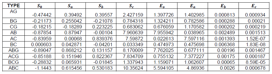
The results of DWT and BPNN training without Clarke’s transformation shown that MSE is 0.056214 and MAE is 0.154754, and with Clarke’s transformation show that MSE is 0.053876 and MAE is 0.150301. Percentage of MSE Validity obtains about 4.159 % and MAE obtains about 2.877 % compare to without preprocessing Clarke’s transformation and plotting of the best linear regression that relates the targets to the outputs are shown in Fig.5 and Fig. 6.
Results of using DWT and Cascade Forward Back Propagation Network (CPBPPN)
Similar to the feed Forward Back propagation Network, the parameters of the training of the detail coefficients of wavelet has various parameters, namely S0,Sα, Sβ, Sγ, Q0, Qα, Qβ, Qγ and wavelet energy E0 , Eα, Eβ and Eγ for various types of faults were set as input variables of the neural network. The data sets were generated by considering the different operating conditions, for example, the different values of inception angles are ranging between 0 and 180 degrees, different values of fault resistances are varied between 0 and 200 ohm and different fault distances take places from 0 to 200 km. Discreet combination (A-BC- G) of faults classification obtained by defining 1 for the value more than 0.6 and 0 for the value less than 0.4.
The results of DWT and BPNN training without Clarke’s transformation, it found that MSE is 0.073929 and MAE is 0.1421057. Meanwhile, with Clarke’s transformation, where the MSE is found to be 0.062201 and MAE is 0.129653, Percentage of MSE Validity achieves about 15.863 % and MAE for about 8.763 % compare to without preprocessing Clarke’s transformation. The plotting of the best linear regression that relates the targets to the outputs are shown in Fig. 7 and Fig.8. The simulation results for various neural network combination / architecture were presented in Table 5. The feed forward back propagation network shows better performance with the MSE and MAE have lesser error compared to the performance of Cascade forward back propagation network. It is shown that the MSE and MAE of FFBPPN have a smaller value than CPBPPN. By adopting Clarke’s transformation, it was yielded that MSE and MAE have smaller value compared to the network without Clarke’s transformation on FFBPPN and CPBPPN. Among all the architectures, the best architect was 12-24- 48-4.
Conclusion
This paper is aimed to compare and explore the practicability of Feed forward back propagation and Cascade forward back propagation network in ANN models in order to recognize fault classification and detection on parallel transmission lines. This approach applies Daubechies4 (db4) as a mother wavelet. Various circumstances have been investigated, including variation on distance, fault resistance and the initial angle.This study also compare the results of training BPPN and DWT with and without Clarke’s transformation, where the results exhibits that using the Clarke’s transformation in training will create smaller MSE and MAE, compared to training without Clarke’s transformation. Among the three structures, the best architects result is 12-24-48-4. The Feed forward back propagation algorithm of Artificial Neural Network (ANN) models performed better results than Cascade forward back propagation algorithm models, particularly in fault classification and detection on parallel transmission lines.
Acknowledgment
The authors would like to thank Research, Technology and Higher Education Ministry of Indonesia for supporting the Research.
REFERENCES
[1] A. M. Shiddiq Yunus, A. Abu-Siada, and M.A.S. Masoum, Improving dynamic performance of wind energy conversion systems using fuzzy-based hysteresis current-controlled superconducting magnetic energy storage, IET Power Electronics, 5(8), pp. 1305-1314. 2012.
[2] A. M. Shiddiq Yunus, A. Abu-Siada, and M.A.S. Masoum, Effects of SMES on dynamic behaviours of type D-Wind Turbine Generator-Grid connected during short circuit. IEEE Power and Energy Society General Meeting, 6039276. 2011.
[3] B. Polajzer, G.s. Tumberger, S., Seme, D Dolinar, Detection of voltage sources based on instantaneous voltage and current vectors and orthogonal clarke’s transformation, IET. Gener .Transm. Distrib, 2,(2), 219–226, 2008.
[4] Chaari,M. Meunier, F. Brouave, Wavelet a new tool for the resonant grounded power distribution systems relaying, IEEE Trans. on Power Delivery, Vol. 11 , (3), 1301-1308. 1977.
[5] Jamian, J.J., Mohd Zin, A.A., Saini, M., Mustafa, M.W., Mokhlis, H., A Novel TVA-REPSO technique in solving generators sizing problems for South Sulawesi Network, Przeglad Elektrotechniczny, Vol. 89, Issue 2 A, pp. 170-174, 2013.
[6] Saini, M., Mohd Zin, A.A., Mustafa, M.W., Sultan, A.R., Nur, R., Algorithm for fault location and classification on parallel transmission line using wavelet based on Clarke’s transformation. International Journal of Electrical and Computer Engineering, Vol. 81, Issue 2, pp. 699-710. 2018.
[7] C.H. Kim, R. Aggarwal, Wavelet transforms in power systems, IET Power Engineering Journal, 15, 193-200, 2001.
[8] Y.H. Song, A.T. Johns, Q.Y. Yuan, Artificial Neural Network based Protection Scheme for Controllable Series compensated EHV Transmission Lines, IEE Proc. on Gener., Transm. and Distr, 143, 2032-2040. 1996.
[9] J.Ezquerra, V. Valverde,I. Mazo´n, A.J. Zamora, JJ Zamora, Field programmable gate array implementation of a fault location system in transmission lines based on artificial neural networks, IET Gener. Transm. Distrib, 5, (2), 191– 198, 2011.
[10] W.J.Cheong, R.K.Aggarwal, Accurate fault location in high voltage transmission systems comprising an improved thyristor controlled series capacitor model using wavelet transforms and neural network, Transmission and Distribution Conference and Exhibition, 2, 840–845, 2000.
[11] R.G.Maryam, M.R.istr Shakarmi, F.Namdari, Detection and classification power quality distribunce using neural Network based discrete wavelet trandform, J. Electrical Systems, 12 (1), 158 – 173, 2016.
[12] P. Chiradeja, A. Ngaopitakkul, Prediction of Fault Location in Overhead Transmission Line and Underground Distribution Cable Using Probabilistic Neural Network, P. Chiradeja, A. Ngaopitakkul, International Review of Electrical Engineering. Vol 8, No 2 (2013), pp. 762-768. 2013.
[13] Sudha Gopal, Valluvan K. R, A Novel Approach to Fault Diagnosis of Transmission Line with Rogowski Coil, International Review of Electrical Engineering. Vol 9, No 3, pp. 656-662. 2014
[14] Y. Menchafou1, M. Zahri, M. Habibi, H. E. Markhil, Extension of the Accurate Voltage-Sag Fault Location Method in Electrical Power, J. Electrical Systems, 12(1), 33 – 34, 2016.
[15] K.M.Silva, B.A. Souza, N.S,D. Brito, Fault Detection and Classification in Transmission Lines Based on Wavelet Transform and ANN’, IEEE Trans. on Power Delivery, Vol. 21 (4). 2058-2063, 2006.
[16] F.B. Costa, K.M. Silva, B.A. Souza, K. M. C., Dantas, N. S. D. Brito, A Method for Fault Classification in Transmission Lines Based on ANN and Wavelet Coefficients Energy, International Joint Conference on Neural Networks, Sheraton Vancouver Wall Centre Hotel, Vancouver, BC, Canada, July 16-21, 2006.
[17] I.K.Yu, Y.H.Song, Wavelet analysis and neural networks based adaptive single pole auto reclosure scheme for EHV transmission systems, International Journal of Electrical Power & Energy Systems, pp. 465–474, 1998.
[18] L.L. Lai, F. Vaseekar, H. Subasinghe, N. Rajkumar, A. Carter, B.J. Gwyn, , Fault location of a teed-network with wavelet transform and neural networks’, in: DRPT International Conference on Electric Utility Deregulation and Restructuring and Power Technologies, pp. 505–509, 2000
[19] B. Alberto, B. Mauro, D. Mauro, A. N.Carlo, P.Mario, Continuous-Wavelet Transform for Fault Location in Distribution Power Networks: definition of mother wavelet inferred from fault originated transeient , IEEE Trans. on Power Delivery, Vol 23,No 2, May 2008, pp. 380-389
Authors: Prof. Makmur Saini is with Power Generation Engineering Study Program, Mechanical Engineering Department, State Polytechnic of Ujung Pandang, Makassar 90245, Indonesia, Email: makmur.saini@poliupg.ac.id; Dr. A. M. Shiddiq Yunus is with Energy Conversion Study Program, Mechanical Engineering Department, State Polytechnic of Ujung Pandang, Makassar 90245, Indonesia, Email: shiddiq@poliupg.ac.id; Dr. Ahmed Rizal Sulthan is with Electrical Engineering Department, State Polytechnic of Ujung Pandang, Makassar 90245, Indonesia, Email: rizal.sultan@poliupg.ac.id; Muh.Ruswandi Djalal, MT is with Power Generation Engineering Study Program, Mechanical Engineering Department, State Polytechnic of Ujung Pandang, Makassar 90245, Indonesia, Email : wandi@poliupg.ac.id; Prof. M. W. Mustafa, University Technology Malaysia, Email:wazie@fke.utm.my, Dr. Rahimuddin, Naval Engineering Department, Hasanuddin University, Gowa, Indonesia, Email: rahimnav@gmail.com; Ikhlas Kitta, Electrical Engineering Department, Hasanuddin University, Indonesia, Email: ikhlaskitta@gmail.com;
Source & Publisher Item Identifier: PRZEGLĄD ELEKTROTECHNICZNY, ISSN 0033-2097, R. 96 NR 4/2020. doi:10.15199/48.2020.04.04
