Published by Maciej GWOZDZIEWICZ1, Piotr KISIELEWSKI2, Wroclaw University of Science and Technology (1), KISIELEWSKI Sp. z o.o. (2)
Abstract. The papers deals with six-phase 2 kW 2-pole induction motor without enclosure. The motor is made of laser-cut construction steel , electrical steel and copper sheets. Shaft, two flange cartridge bearing units are machined by the milling machine. Bearings, stator winding and insulation are standard. The goal of the work is experimental investigation of impact of failures of the supply or stator winding on the motor performances.
Streszczenie. Artykuł przedstawia 6-fazowy 2-biegunowy silnik indukcyjny o mocy 2 kW. Model fizyczny silnika wykonano z blach ciętych laserem. Celem pracy jest weryfikacja wpływu uszkodzeń zasilania lub uzwojenia stojana silnika na jego właściwości. (Bezkadłubowy 6-fazowy silnik indukcyjny).
Keywords: enclosure-less, six-phase, induction motor, stator failure, supply failure
Słowa kluczowe: silnik bezkadłubowy, 6 faz, silnik indukcyjny, uszkodzenia stojana, uszkodzenia zasilan
Introduction
Laser cutting technology is being increasingly popular in electric machines manufacturing [8]. It enables to realize almost arbitrary project. The cost of laser cutting are going to even with cost of machining technology. Furthermore, AC electric machines can be built without enclosure. Of course, it reduces stiffness of the machine but simultaneously it decreases thermal resistance.
FEM motor model
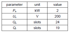
In Ansys Maxwell software 2D FEM 6-phase 2-pole induction motor field-circuit model was built [1-2]. Rated motor parameters are given in Table I.
Table 1. The parameters of the sensor
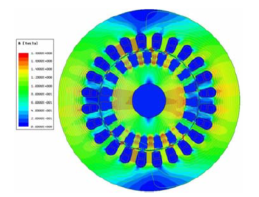
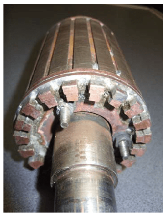
Stator double layer winding consists of 24 coils made of round double enamelled copper wire with coil pitch ys=5/6. Rotor winding consists of quasi-trapezoidal copper bars. Each rotor bar includes 2 rectangular copper bars with wider one at the bar top. Rotor slot openings are quite wide to decrease rotor winding leakage reactance and to obtain high starting and maximum motor torques. FEM motor model is presented in Fig. 1. Magnetic field distribution for rated load power is shown in Fig. 2.

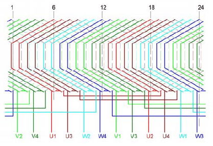
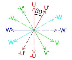
Motor is supplied by 6-phase sinusoidal voltage. The supply voltage consists of double 3-phase voltage with phase displacement equal to 30 degrees. Stator winding is connected in star [3-4]. Stator 6-phase winding distribution is given in Fig. 3. Supply 6-phase voltage vector diagram is presented in Fig. 4.
Motor construction
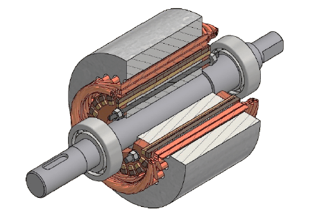
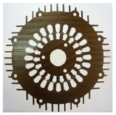
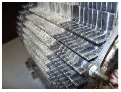
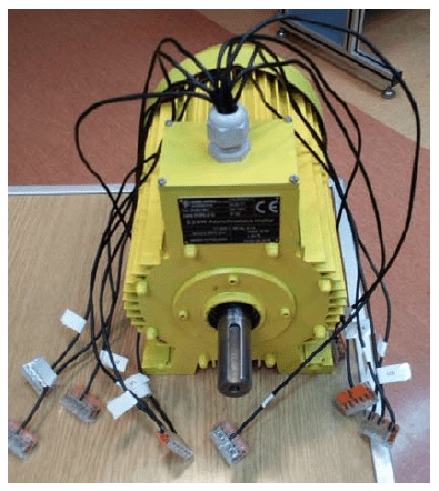
Stator and rotor sheets, rotor bars and rings and motor construction sheets are laser cut. Rotor rings connect bars and also keep rotor sheets due to 3 pressing rods. Motor construction is show in Fig. 5. Stator and rotors sheets are presented in Fig. 6. Stator sheets includes on the external edge cooling ribs and holes for pressing rods which keep the whole motor construction. The motor bearings type is 6205 2Z C3. Motor stator is presented in Fig. 7 and motor rotor is given Fig. 8. Finished motor is shown in Fig. 9.
Experimental results
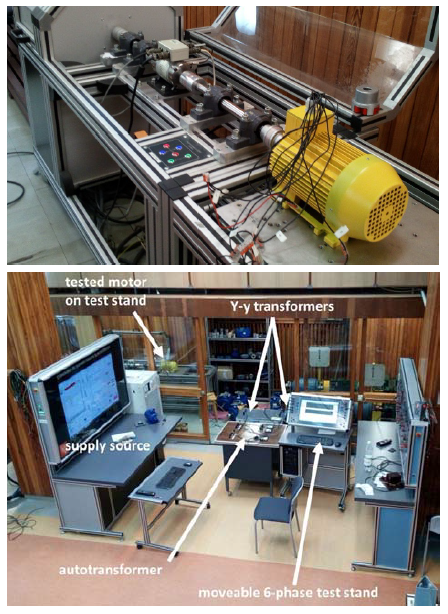
In laboratory of electric machines at Division of Electrical Machines and Measurements experimental investigation of designed and built enclosure-less 6-phase 2-pole motor was done. Test stand is presented in Fig. 10. Six-phase voltage was obtained by 3 transformers. Two of them were used to get double 3-phase voltage with phase displacement equal to 30 degrees. Additional third autotransformer was used to even RMS magnitude of all 6-phase voltages. Schema of the supply is presented in Fig. 11.
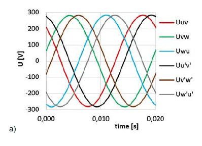
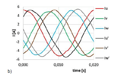
In the beginning, the motor was supplied by 6-phase voltage Un=200 V at rated frequency fn=50 Hz and loaded by rated load power Pn=2.0 kW. Voltage and motor current in time domain is given in Fig. 12. Comparison of the obtained experimental and simulation results is presented in Tab. 1.
Afterward, phase failures in the motor or supply were investigated [5-7]. The failures were simulated by switching-off one or more phase from the motor by circuit breakers which are shown in Fig. 13.


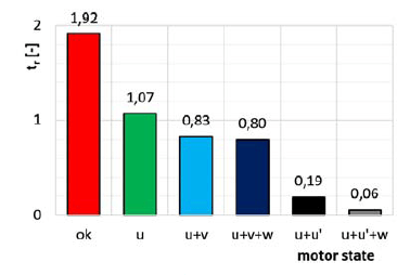
Firstly, influence of the phase failures on the motor breakdown torque was examined. Load torque was being increased with speed 10 Nm per 1 s. The results are given in Fig. 14. Next, influence of the phase failures on the motor starting torque was investigated. Supply voltage during measurement was equal to 80 V, starting torque value was referred to rated voltage Un=200 V. The results are presented in Fig. 15.
Table 2. Comparison of the obtained experimental and simulation results

Conclusions
Six-phase induction motor is very good alternative to three-phase induction motor due to much more reliability. In case of one-phase failure the motor performance enables motor to work. This solution can be very good proposition for traction electrical drives for which reliability is the most significant requirement.
It is possible to build enclosure-less electric motor for which almost all parts are made by laser cutting of steel, electrical steel and copper sheets. It is good alternative for standard motors with die-cast or welded enclosure.
Calculations have been carried out using resources provided by Wroclaw Centre for Networking and Supercomputing (http://wcss.pl), grant No. 400.
REFERENCES
[1] Livadaru L., Bobu A., Munteanu A., Vîrlan B. and Simion A., FEM-based Analysis on the Operation of Three-Phase Induction Motor connected to Six-Phase Supply System. Part 1 – Operation under healthy conditions, 2017 International Conference on Electromechanical and Power Systems (SIELMEN), pp. 119-124, December 2017
[2] Livadaru L., Bobu A., Munteanu A., Vîrlan B. and Simion A., FEM-based Analysis on the Operation of Three-Phase Induction Motor connected to Six-Phase Supply System. Part 2 – Study on fault-tolerance capability, 2017 International Conference on Electromechanical and Power Systems (SIELMEN), pp. 125-130, December 2017
[3] Nanoty A.S. and Chudasama A.R., Design of Multiphase Induction Motor for Electric Ship Propulsion, 2011 IEEE Electric Ship Technologies Symposium, pp. 283-287, May 2011.
[4] Bernatt J. and Glinka T., Electric machines with 6-phase winding, Wiadomości Elektrotechniczne 12/2008, pp. 14-19, 2008
[5] Abdelwanis M.I. and Selim F., A Sensorless Six-Phase Induction Motor Driving a Centrifugal Pump System, 2017 Nineteenth International Middle East Power Systems Conference (MEPCON), pp. 242-247, December 2017
[6] Ai Y., Wang Y. and Kamper M.J., Torque Performance Comparison from Three-Phase with Six-Phase Induction Machine, Proceedingsofthe 2009 IEEE International Conference on Mechatronics and Automation, pp. 1417-1421, August 2009
[7] Hammad R.A., Dabour S.M. and Rashad E.M., Performance of a Six-Phase Induction Motor Fed from a Z-Source Inverter under Faulty Conditions, 2017 Nineteenth International Middle East Power Systems Conference (MEPCON), pp. 1333-1338, December 2017
[8] Wilczynski W., Influence of magnetic circuit production for their magnetic properties, J. Mater. Sci., 8(2003) ,No. 38, 4905– 4910, August 2003
Authors: Pd.D. Maciej Gwoździewicz, Electrical Engineering Faculty at Wroclaw University of Science and Technology, E-mail: maciej.gwozdziewicz@pwr.edu.pl, Ph. D. Piotr Kisielewski, KISIELEWSKI Sp. z o.o., internet address: http://www.kisielewski.pl, E-mail: office@kisielwski.pl
Source & Publisher Item Identifier: PRZEGLĄD ELEKTROTECHNICZNY, ISSN 0033-2097, R. 95 NR 6/2019. doi:10.15199/48.2019.06.26
