Published by Michal IVANČÁK, Michal KOLCUN, Zsolt ČONKA, Dušan MEDVED, Technical University of Košice, Slovakia
Abstract. Intelligent networks are a broad topic these days, so new possibilities need to be explored in this area. This article describes network modelling through software that replaces mathematical computation, facilitates and speeds up this process. The model draws data from real distribution system conditions from the average village in Slovakia. This model also tests its reliability as well as the impact of various attributes such as prediction.
Streszczenie. Inteligentne sieci są istotnym, aktualnym tematem, dlatego należy badać nowe możliwości w tej dziedzinie. W artykule opisano modelowanie sieci za pomocą oprogramowania, które zastępuje obliczenia matematyczne, ułatwiając i przyspieszając proces analizy. Model bazuje na rzeczywistych danych systemu dystrybucyjnego średniej miejscowości na Słowacji. Model ten analizuje również jego niezawodność a także wpływ różnych aspektów, takich jak prognozowanie. (Modelowanie mikrosieci jako podstawy do opracowania modelu inteligentnej sieci).
Keywords: microgrid, smart grid, electromobility, prediction, Matlab – Simulink.
Słowa kluczowe: mikrosieć energetyczna, inteligentna sieć, elektromobilność, prognozowanie, Matlab – Simulink.
Introduction
In these days “Smart” is as a very popular term. It usually refers to different products with an increasing degree of computing power. Smart products such as smart phone, smart TV or other smart electronics with a variety of features and applications are now very popular. Electricity is currently a strategic “raw material” and its importance in the future years is clearly growing. For this reason, increasing emphasis is placed on the stability, safety and security of the electricity supply to end customers. Therefore, the computerization is increasingly being introduced into the electricity system during the time. Very popular is also the new term “Smart Grid”.
Despite the high popularity of this term, it is not always clear what is meant by it. Smart Grid is often referred to as the network of the future, a network capable of providing a high proportion of distributed production. During the time Smart Grid has almost attracted the attribute of a magic wand able to solve all the problems associated with renewable energy sources connected to the distribution network while reducing the final price of electricity for customers. Among the many definitions available, Fereidon P. Sioshansi’s statement is the most interesting and he interprets the term Smart Grid as follows: “Smart Grid is the best thing we can, but we do not know what it is.”
The many of projects, articles and publications focus on theme of Smart Grid, as well as foreign and domestic conferences. Despite the great popularity, there is a wide inconsistency in the definition of this term. Nevertheless, Smart Grid is often referred also to as the network capable of using more renewable energy sources and distributed production than the current network.
Comprehension of the current Smart Grid network is rather difficult and from costs perspective expensive. It is a long-term process that binds capital over many years. Therefore, it requires a strong commitment from all stakeholders. In addition, it is still not fully verified how the individual technologies within Smart Grid will work together. However, this process of redevelopment is already running, and many countries are launching various pilot projects to demonstrate the feasibility and benefits of this technology.
Implementation of the smart grid
Smart Grid networks have the following features and benefits over classic networks. The biggest difference is the different network topology due to the inclusion of distributed production that causes different energy flow directions. The change is also thanks to the new technologies, two-way communication and the presence of active elements and sensors throughout the system, self-monitoring as well as rapid detection and localization of failures.
Thanks to new technologies, higher reliability, better security, greater convenience for customers and higher efficiency in the use of electricity are expected. Intelligent systems also envisage semi-automatic renewal and autoregeneration as well as adaptive protection and isolation of a potential problem. Customers are thus provided with the integration and provision of new services.
From the distribution point of view, it is the use of centralized resources along with decentralized resources.
Decentralized sources of small capacities deployed across Europe are in line with the European Union’s commitment and commitment to increase its share of renewable energy production to 20% by 2020. A high degree of automation in distribution and transmission systems is expected to reduce system losses and the associated increase in ecology, economy and operational efficiency as well as support for scattered production along with the development and research of new management methods.

Modelling microgrid using Matlab- Simulink software
Modelling is a very good method for making designs thanks to computer calculating performance, especially taking in account complexity of the environment. Of course, in the background of every software there is a set of mathematical formulas that we can use to make modifications more efficiently while changing a constant. So it is not necessary to repeat the entire calculation.
The necessary part of creating an electrical network is adequate preparation which is needed to ensure that the network’s functionality is properly verified to avoid unnecessary investment costs. Without suitable training it would not even be possible. At the same time, the software tools create the right conditions for laboratory testing as well as back-up verification of the functionality of the already implemented project. The basis of the modelling must be precise as possible in order to ensure the accuracy of the results is also close as possible to the reality.
Simulink is a MATLAB extension for simulation and modelling of dynamic systems. It provides the user with the ability to quickly and easily create dynamic system models in the form of block diagrams. Models can be described by equations or can be assembled from blocks representing real system elements. Besides models of physical systems, it is possible to model also control system algorithms including their automatic tuning, signal processing systems, communication and image processing.
This example shows a vehicle-to-grid system used to regulate the frequency on a microgrid when events occur during a full day. The phasor mode of SimscapeTM Power SystemsTM allows a fast simulation of a 24 h scenario.
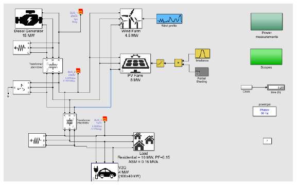
The microgrid is divided into four important parts: A diesel generator, acting as the base power generator; A PV farm combined with a wind farm, to produce renewable energy; a vehicle to grid system installed next to the last part of the topology which is the load of the grid. The size of the microgrid represents approximately a community of a thousand households during a low consumption day in spring or fall. There are 100 electric vehicles in the base model which means that there is a 1:10 ratio between the cars and the households. This is a possible scenario in a foreseeable future.
Diesel Generator
The diesel generator balances the power consumed and the power produced. We can determine the frequency deviation of the grid by looking at the rotor speed of its synchronous machine.
Renewable Energy
In this microgrid are two sources of renewable energy:
1. The photovoltaic power plant produces 3 energy factors: the size of the area covered by the photovoltaic power plant, the efficiency of solar panels and irradiation data.
2. The simplified model of a wind farm produces electricity after a linear relationship with the wind. When the wind reaches the nominal value, the wind farm produces nominal power. The wind power plant emerges from the grid when the wind speed exceeds the maximum wind speed until the wind returns to its nominal value.
Vehicle-to-Grid
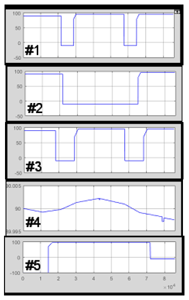
The V2G has two functions: Controls the charge of the batteries connected to it and uses the available power to regulate the grid when an event occurs during the day. The block implements five different car-user profiles:
Profile #1: People going to work with a possibility to charge their car at work.
Profile #2: People going to work with no possibility to charge their car at work.
Profile #3: People going to work with a possibility to charge their car at work but with a longer ride
Profile #4: People staying at home. Profile #5: People working on a night shift.
Load
The load consists of a residential load and an asynchronous machine that is used to express the impact of an industrial inductive load (such as a ventilation system) on a microgrid. Residential load monitors the consumption profile with a given power factor. The asynchronous machine is controlled by a square relationship between rotor speed and mechanical torque.
Simulation
Run the model and observe the various range signals inside of it. It is possible to monitor rotor speed behaviour in the range above the model.
Click on the Scopes and Power measurements subsystem to access information from different nodes. The charging status of each vehicle profile is also available in this subsystem. Negative charge state means the car is on the road or not connected.
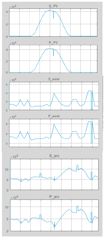
Scenario
Simulation takes 24 hours. The intensity of sunlight is controlled by the normal distribution where the highest intensity is reached at noon. The wind changes significantly during the day and has several peaks and minima. Residential load has a typical formula similar to normal household consumption. It is low during the day, increases to the peak during the evening and decreases slowly at night. Three events affect network frequency during the day:
– the start of the asynchronous machine in the third hour
– a partial cloudiness at midday affecting the production of solar energy
– a wind farms cut off in 22 hours when the wind exceeds the permitted maximum permitted wind energy
Conclusion
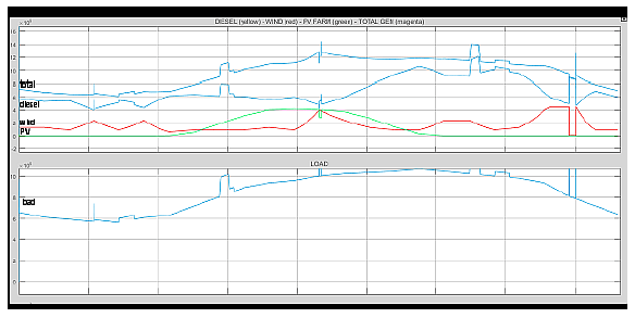
This article describes a simulation that includes power sources (a 15 MW diesel generator, a photovoltaic and wind power plant with outputs of 8 and 4.5 MW), electricity consumption (with a maximum of around 10 MW) and a model of electric vehicle charging as reserve electricity in case of network drops or surpluses. The system also includes unpredictable sources that in combination with the diesel generator and the electric car system keep the network running.
Because of the model is the off-grid system it is not connected to a larger system, it depends on the reliable operation of the largest source. The base is a diesel generator that is not dependent on wind and solar power but provides the maximum space for energy from renewable energy sources. Several measurements have been performed within the model, demonstrating the functionality of the model and its stability under the given conditions. On a given model, it would still be appropriate to monitor the quality of electrical energy, especially the frequency, since large frequency fluctuations have an undue influence on the functionality of the elements in the network.
Acknowledgement This work was supported by the Ministry of Education, Science, Research and Sport of the Slovak Republic and the Slovak Academy of Sciences under the contract No. VEGA 1/0372/18.
REFERENCES
[1] Sioshansi F. P. et al., Smart Grid: Integrating Renewable, Distributed & Efficient Energy, 510 (Academic Press, 2011)
[2] Volčko V., Smart Grid: Vplyv na prevádzku, bezpečnosť a stabilitu elektrizačnej sústavy, (2015), http://www.fei.stuba.sk/docs//2015/autoreferaty/Volcko_autoref.pdf
[3] Borlase S., Smart Grids: Infrastructure, Technology and Solutions, 577, (CRC, 2013)
[4] Momoh J., Smart Grid: Fundamentals of Design and Analysis, 216, (IEEE P., 2012)
[5] Liptai P. et al., Check measurements of magnetic flux density: Equipment design and the determination of the confidence interval for EFA 300 measuring devices, Measurement. Vol.111, p. 51-59 (2017)
[6] Mikita M. et al., Sizing optimization of PV-battery hybrid for public lighting system Acta Electrotechnica et Informatica. Vol.16, no. 2 p. 25-28 (2016)
[7] Špes M. et al., Possibilities of increasing transmission capacity
overhead lines, Acta Electrotechnica et Informatica. Vol. 16, no.3, p. 20-25 (2016).
[8] Špes M. et al., Verification of the distance protection relay operation, Zeszyty Naukowe Politechniki Rzeszowskiej: Elektrotechnika. Vol. 25, no. 1, p. 15-25 (2017).
[9] Petráš J. et al., Human interfaces used for smart electric installation control, Elektroenergetika 2017. – Košice: TU, 2017 p. 94-98. (2017)
[10] Kanálik M., Computation of harmonic flows in three-phase systems, Acta Electrotechnica et Informatica. Vol. 7, no. 3, p.41-45 (2007).
[11] Z. Čonka, M. Kolcun: Impact of TCSC on the Transient Stability In: Acta Electrotechnica et Informatica. Vol. 13, no. 2 (2013), p. 50-54. – ISSN 1335-8243 Available on internet http://www.versita.com/aei.
[12] Mathworks, Documentation of using Matlab, https://www.mathworks.com/
Authors: Ing. Michal Ivančák, Technical University of Košice, Faculty of Electrical Engineering and Informatics, Department of Electric Power Engineering, Mäsiarska 74, 04001 Košice, Slovakia, E-mail: michal.ivancak@tuke.sk; Dr.h.c. prof. Ing. Michal Kolcun, PhD. Technical University of Košice, Department of Electric Power Engineering, Mäsiarska 74, 04001 Košice, Slovakia E-mail: michal.kolcun@tuke.sk; Ing. Zsolt Čonka, PhD. Technical University of Košice, Department of Electric Power Engineering, Mäsiarska 74, 04001 Košice, Slovakia E-mail: zsolt.conka@tuke.sk; Ing. Dušan Medveď, PhD. Technical University of Košice, Department of Electric Power Engineering, Mäsiarska 74, 04001 Košice, Slovakia E-mail: dusan.medved@tuke.sk. The correspondence address is: michal.ivancak@tuke.sk.
Source & Publisher Item Identifier: PRZEGLĄD ELEKTROTECHNICZNY, ISSN 0033-2097, R. 95 NR 8/2019. doi:10.15199/48.2019.08.11
