Published by Paweł PIJARSKI, Sylwester ADAMEK, Robert JĘDRYCHOWSKI, Klara SEREJA,
Lublin University of Technology, Department of Electrical Networks and Security
Abstract. An increasing number of connected prosumer installations, mainly photovoltaic ones, can cause problems with the operation of lowvoltage networks such as voltage fluctuations. These problems can be solved by an adequate control of the sources operation within one transformer substation. The article presents a concept of a controller that ensures access to the data that describe the network operating conditions and the energy sources installed there as well as allows control of the micro installations output power.
Streszczenie. Coraz większa liczba przyłączanych instalacji prosumenckich, głównie fotowoltaicznych, może być przyczyną występowania problemów w pracy sieci niskiego napięcia, takich jak m.in. wahania napięcia. Problemy te mogą być rozwiązane poprzez odpowiednie sterowanie pracą źródeł w obrębie jednej stacji transformatorowej. W artykule zaprezentowano koncepcję sterownika, który zapewnia dostęp do danych obrazujących warunki pracy sieci i zainstalowanych w niej źródeł energii, jak również umożliwia sterowanie mocą wyjściową mikroinstalacji. (Monitorowanie wpływu prosumenckich mikroinstalacji na parametry elektryczne systemów sieci niskiego napięcia).
Keywords: microgeneration, power quality, SCADA, Smart Grid.
Słowa kluczowe: mikrogeneracja, jakość energii, SCADA, Smart Grid.
Introduction
The development of distributed generation will lead to the emergence in the low-voltage network of phenomena occurring so far in higher voltage networks. Particularly important will be phenomena causing changes in power flows and deterioration of power quality parameters, which pose potential threats for devices connected to the network. In order to counteract them, it will be necessary to monitor the work of those parts of the network in which a large number of micro-sources with a relatively high power have been installed. Analysis of the LV (low-voltage) network operation requires in such a case the implementation of complicated, multi-variant simulations and analyses, e.g. voltage conditions in the LV network with various levels of saturation with micro installations, different structure and load profile.
The essence of the problem
According to the relevant act [1], micro-installation is “a renewable energy installation with a total installed electrical power not exceeding 40 kW, connected to a power grid with a rated voltage lower than 110 kV or with a heat-generating power in the combination no greater than 120 kW”. The connection of low-voltage power sources of this type to end users, according to another act [2], can take place in two ways:
• on the basis of the notification,
• by submitting an application for determining the terms of connection to the distribution network
The article focuses on the first of the above-mentioned ways of connecting micro-installations – based on the application.
The development of micro-installations, especially photovoltaics, caused by a drop in their prices seems to be unavoidable. As a consequence, one should expect various technical problems, among which the most serious will probably be voltage impact [3, 4], resulting from the power flow from the point of connection of these sources towards the MV/LV (medium voltage/low-voltage) substations. It results from the fact that the correlation of power generated in them with the demanded power is small.
Figure 1 shows that there are periods when the maximum power generated in a solar installation does not coincide with the maximum demand. This situation is unfavourable because it will cause power flows towards the MV/LV transformer and, as a result, contribute to the “voltage boosting” effect, which is the inverse of the voltage drop effect.

The solution to this problem can be:
• control of the reactive power of sources,
• control of the active power of sources,
• turning off the “necessary number of sources”.
Each of these methods has its advantages and disadvantages.
Proposal of control algorithm
Currently, no voltage regulation is carried out in low voltage networks in a continuous mode. In connection with the anticipated technical problems during the operation of sources, a grid control algorithm should be developed, taking into account the use of certain regulatory sources, or even, if necessary, limiting their power. An attempt to develop an analogous algorithm for medium voltage networks is shown, for example, in [4]. Voltage control in the low-voltage network will be possible after fulfilling several conditions:
• the network will be observable to a certain extent – voltage in selected nodes and powers generated in sources are known,
• we have information about the topology and parameters of network branches,
• we have an algorithm allowing to determine the value of extortion in the network (voltages, generated power), so as to ensure correct operation of the system,
• it is possible to send calculation results to generation devices in the network and change the parameters of their operation in accordance with current conditions.
The condition of observability of network operation parameters with the current state of technical solutions seems to be feasible. The network topology and its data are also possible to collect, although this process can be tedious due to the significant number of low-voltage lines.
Assuming that approximate voltage values can be determined, e.g. by using models analogical to those described in [4], the grid control algorithm should first of all eliminate any overruns, i.e. meet the condition:
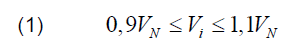
where VN is the nominal voltage of the network, and Vi is the supply voltage at the i-th receiver.
Then, if the installed sources allow for adjusting their passive and active power, it is possible to optimise the system’s operation in such a way that the voltage deviations of the supplying power from the rated voltage are as low as possible. In practice, this would mean minimising the voltage quality indicator described in [4] and given by the formula:

where VN is the nominal voltage of the network, Vi is the supply voltage at the i-th consumer and n is the number of energy users. The practical implementation of the control algorithm will require the expansion of the network infrastructure with measurement and data transmission systems.
Control system
When organising a control system for the LV network with micro-sources connected, it is necessary to define the goals it should implement. They were indirectly defined in previous chapters and include:
• monitoring of electrical parameters at selected points of the LV network, cooperation with micro energy sources,
• implementation of algorithms allowing for network operation control,
• ensuring communication between cooperating elements of the system.
• retransmission of data to the SCADA (Supervisor Control and Data Acquisition) system of the distribution network operator.
To realise these assumptions, the concept of a control system was developed, based on cooperating devices, creating a distributed architecture and working in a master-slave system.
The main element of the system is the master controller installed in the LV transformer substation MV/LV. It has several important functions, which include:
1. Measurement of basic electrical parameters on the LV transformer side and in outgoing circuits.
2. Determination of the criterial values necessary to assess the operation status of the network in the main circuit and individual outflows, allowing their assessment in the control process.
3. Implementation of the network control algorithms adopted for a given system described in the previous chapter.
4. Ensuring communication with individual slave controllers, taking into account the adopted communication technology.
5. Network monitoring, generation of warnings and alarms.
6. Controlling the operation of individual slave controllers, and thus the operation of energy sources, taking into account the specificity of individual sources.
7. Providing information to the network operator’s SCADA system. This will be information about measurement parameters and selected alarm signals.
8. Visualisation of the network and system operation status.
Nevertheless, slave controllers are also important. They are installed in the switchgears of the building or the LV installation connector to which the source has been connected. They perform functions of the source operation monitor, the power grid at the connection point and prosumer installation. Their tasks include:
1. Measurement of basic electrical parameters with special consideration of those that are necessary for the operation of the control algorithm.
2. Retransmission of data to the master controller.
3. Direct or indirect control of the operation of the source converter circuit, including the operation of the prosumer installation.
Low-power sources are connected to the network via inverters equipped with their own controllers. The operation of the slave controller can be analysed depending on the possibility of cooperation between the slave controller and the source controller.
In the least favourable case, when such cooperation for technical or other reasons is not be possible, the role of the controller will be limited to the measurement of the set values, their retransmission to the master controller. It would also be possible to disconnect the source in a prosumer installation in critical situations. In the second case, it is possible to assume supervision of the source operation through the local controller assigned to the inverter controlling its operation. The third case assumes full control over the source converter, which would allow the implementation of generation control algorithms directly in the slave controller. In all cases, it is necessary to maintain the autonomy of operation of local systems, so that even in the absence of communication with the master controller, safe operation of the source is guaranteed.
The presented control system can be implemented on the basis of existing solutions. The PLC controller is an example of this. Thanks to their modular structure, the controllers allow for extending the possibilities offered by classic automation devices [5].

PLC controllers have a number of possibilities to obtain information about the operation of the LV network and prosumer installation through the controller modules and elements cooperating with them. The first group of elements includes measuring modules [6]. The second group of elements are communication modules allowing for exchange of information between controllers and other elements, e.g. source controller or energy meters. Communication is possible by using: links RS 232, RS 485, TCP/IP networks, wireless links.
Practical implementation of a LV network monitoring system
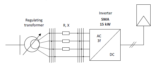
The practical implementation of the distributed monitoring system was carried out on cooperating controllers of the WAGO series 750-880/025 (Fig. 2) equipped with additional tele-control functions and a 15 kW photovoltaic system with a three-phase SMA inverter. For research purposes, resistors and reactors with adjustable setpoints allowing simulation of the LV line parameters were also used (Fig. 3).
In the proposed solution, in order to conduct research experiments, the controllers work as master and slave and perform the partial tasks described in the previous section. The controllers implement both data acquisition functions and control functions. The slave controller has been equipped with an analogue input card for measuring voltages and currents in a three-phase system and binary outputs for controlling the inverter’s power limitations, using the intermediate relay separating the controller and the inverter. In addition, the controller has communication interfaces to view its work status, current measured values, remote programming as well as communication with the master controller. It should be emphasised that the power measurement carried out in the controller is informative, and the regulated parameter is voltage. The master controller also has a three-phase measurement module, binary inputs and outputs. However, its main task is the acquisition of data, including those obtained from the slave controller and the implementation of control algorithms for the network. The software part of the project was created in the CoDeSys environment used for programming PLC applications.
The measuring modules used in both controllers to monitor selected electrical circuits allow for three-phase measurement of selected electrical parameters. The current measurement in the slave controller is carried out using Rogowski coils installed in the inverter output circuit. In the measuring module, the currents from individual phases are connected to the inputs IL1, IL2, IL3 and IN in the correct order. Voltage signals are applied to terminals VL1, VL2, VL3 and VN. On the basis of these signals, the module is able to measure currents, voltages as well as determine reactive, active and apparent power values as well as energy, frequency and the power factor. This module is distinguished by the measurement of current in the neutral conductor as well as the measurement of up to 41 harmonics in the network. Thanks to the fact that the measurement module allows to carry out a 4-quadrant power analysis, it is possible to constantly analyse information on the current operating state of the inverter.
The control system that manages the operation of the inverter implemented in the slave controller allows for exchange of data with the environment and making it available to the user. An important element of the control system is data visualisation, allowing user-machine communication and presentation of current information on the work of micro-installations. Visualisation and communication was carried out on the basis of standard libraries offered by the controller manufacturer. Access to the visualisation is possible through the built-in WEB Server driver. Another important element of the system is the possibility of its extension with additional modules that allow the controller to be adapted to new tasks.
The task of the local control algorithm implemented in the slave controller is to enable the control of the stages limiting the power produced by the PV installation. For the needs of the tests, 5 stages of power limitation described from 0 to 4 were adopted. Stage 0 means no restrictions, stage 4 denotes zero active power generation. For a system with an SMA inverter the regulation range can be specified from 0 to 24. The control algorithm consists of the following parts:
1. Initialisation of the controller – when it is started, all default parameters of the declared parameters are read and the service programs, e.g. the operation of the measurement module, are started.
2. Selecting the operating mode – the controller can work in two modes – automatic and manual. The choice of mode takes place on the main site of the application. In manual control mode, the degree of restriction is set by the user. Changing the operating mode to automatic activates the part that implements the automatic restriction control algorithm.
3. Automatic operation, limiting the generated power – in the case when the measured voltage is greater than the set upper value, the power value is reduced by one degree with the time delay required for the inverter response.
4. Automatic operation, raising the generated power – in the case when the measured voltage is lower than the set lower value, the permissible value of the power generated by one degree is raised with the time delay required for the inverter reaction.
5. Cancellation of restrictions – due to the fact of hysteresis between the upper and lower voltage set for the controller, a mechanism was developed whose task is to maximise the power generated at the set voltage limits. For this purpose, two mechanisms were introduced: the first attempts to return to a lower degree of restriction after a set time (e.g. 30 min.), the second resets the restrictions once a day, in the evening.


The sample results obtained during the experiments performed on the model are shown in figure 4 and figure 5. The slave controller has monitored the value of the varying voltage at the connection point of the inverter and on this basis made a power reduction (Fig. 4). The influence of changes of this action on the voltage at the connection point is shown in figure 5. In this system it is also possible to control voltage with simultaneous change of the inverter operation characteristics and generation curtailment [7].
In the master controller, the control algorithm works only in the simulation mode. The controller controls the network parameters, but it has no possibility to influence it. This is due to the inability to change the parameters of the actual supply network (e.g. by changing the transformer ratio, overloading the transformer or circuit) with which the control model has been linked. However, this does not interfere with testing the system at the given criterion values of the developed network management algorithms using a distributed controllers system.
An additional benefit resulting from the implementation of the monitoring system is the ability to test various data exchange methods between cooperating system nodes (PLC controllers). The assumption was made in the works that solutions previously known from SCADA systems managing the MV network will be used. Thanks to this approach, the solutions shown are compliant with the recommendations described for Smart Grid and allow for cooperation with other elements that make up the intelligent system [8].
The controllers used allow the use of RS232 and RS485 links and communication in the Ethernet network. The IEC 61850 standard for communication between controllers is used in the control system created. This standard has imposed the choice of Ethernet. Thanks to its application, it is possible to monitor communications based on cyclic reading of analogue data as well as GOOSE messages used for transmission of binary signals (orders and events). Information on the duration of individual data exchange processes collected in this way allowed to include them in the work of the tested algorithms (Fig. 6).

In addition, data exchange was organised using the DNP3 protocol between the system simulating the SCADA system used by the operator to manage the power grid, and the master controller of the implemented model.
The implemented control system assumes the possibility of influencing the operation of the inverter. It was assumed that if we want to be able to regulate the voltage in the network, such cooperation is necessary. The legal aspect was omitted in this case. Energy law in its current form does not allow for the control of a prosumer installation [1].
Conclusion
The development of prosumer installations market, despite the delays resulting from the legislative turmoil, seems rather foregone today. In many Polish communes, projects for the purchase and installation of renewable sources with EU co-financing are implemented. Technical problems related to the depletion of power generated to be collected are likely in the near future. They can be solved in various ways – for example by extending the network with additional lines or MV/LV stations, just as it happens when the power demand increases. However, it seems economically reasonable to apply also solutions that improve the use of existing networks through the use of available, intelligent ICT solutions.
The development of new methods of controlling the operation of dispersed energy sources is necessary despite the lack of legal solutions. The created control system based on PLC controllers allows to show their technical capabilities. It is a flexible system in which it is easy to make subsequent changes by adding new nodes (PLCs) and changing the control algorithms and communication methods. This system can be easily adapted to support new devices appearing on the network, such as energy storage, introducing new challenges in controlling the operation of the network.
REFERENCES
[1] The Renewable Energy Sources Act of 20 February 2015 (Ustawa z dnia 20 lutego 2015 o odnawialnych źródłach energii). Dz.U. 2015 poz. 478, http://isap.sejm.gov.pl/
[2] The Energy Law Act of 10 April 1997 (Ustawa z dnia 10 kwietnia 1997 r. – Prawo energetyczne). Dz.U. 1997 nr 54 poz. 348, http://isap.sejm.gov.pl/
[3] Kacejko P., Pijarski P., Management of microgenerations of renewable energy sources – technical challenge or the marketing impuls?, Rynek Energii, 2016, no 1, 41-45
[4] Kacejko P, Adamek S., Wydra M., Optimal voltage control in distribution networks with dispersed generation, Proceedings of Innovative Smart Grid Technologies Conference Europe (ISGT Europe), Gothenburg, Sweden, 11–13 October 2010, 1-4.
[5] Jędrychowski R., Programmable logic controllers used as information sources for systems to supervise operation of small-scale generation sources, Rynek Energii, 2014, no 1, vol. 110, 30-34.
[6] Jędrychowski R., Data acquisition system for small power generation sources, Poznan University Of Technology Academic Journals. Electrical Engineering, 2012, no 70, 225-231.
[7] Kacejko P., Adamek S., Wancerz M., Jędrychowski R., Possibilities of mitigation of overvoltage caused by intensive PV development in LV grid, Wiadomości Elektrotechniczne, 2017, vol. 85, no 9, 20-26.
[8] IEC Smart Grid Standardization Roadmap. Prepared by SMB Smart Grid Strategic Group (SG3), June 2010, Edition 1.0
Authors: dr inż. Paweł Pijarski, dr inż. Sylwester Adamek, dr inż. Robert Jędrychowski, mgr inż. Klara Sereja, Lublin University of Technology, Department of Electrical Networks and Security, ul. Nadbystrzycka 38A, 20-618 Lublin, E-mails: p.pijarski@pollub.pl, s.adamek@pollub.pl, r.jedrychowski@pollub.pl, k.sereja@pollub.pl.
Source & Publisher Item Identifier: PRZEGLĄD ELEKTROTECHNICZNY, ISSN 0033-2097, R. 95 NR 2/2019. doi:10.15199/48.2019.02.12
