Pubsliehd by Jacek GUMIELA1, Dariusz SZTAFROWSKI1
Politechnika Wrocławska, Katedra Energoelektryki (1)
Abstract. To minimize interference with the environment it is important to make every effort already at the design stage to spare the trouble associated with additional investment later on. Due to the value of land in urban areas, it is beneficial to take necessary measures to reduce the width of the impact zone and optimize the management of these lands. Possible variants of this assumption were analysed on the example of the existing 110 kV line.
Streszczenie. W celu ograniczenia natężenia pola elektrycznego w środowisku warto już na etapie projektowania obiektów elektroenergetycznych dołożyć wszelkich starań minimalizujących uciążliwość nowej inwestycji. W odpowiednich aktach prawnych zostały określone graniczne wartości m.in. pola elektrycznego co determinuje szerokość tzw. pasa technologicznego oraz ograniczenia w zagospodarowaniu sąsiadujących terenów. Na przykładzie istniejącej linii 110 kV poddano analizie możliwe warianty realizacji tego założenia.(Zastosowanie dodatkowych uziemionych przewodów w napowietrznych liniach elektroenergetycznych WN w celu ograniczenia natężenia pola elektrycznego generowanego przez przewody fazowe).
Słowa kluczowe: pole elektryczne, symulacje cyfrowe, metoda elementów skończonych, bezpieczeństwo środowiska.
Keywords: electric fields, digital simulations, finite elements method, safe of environment
Introduction
Electric power lines are the source of electromagnetic field which, for safety reasons, should not exceed the values set out in relevant legislation [1]. In the design phase of new infrastructure these objects are located far from human settlements. However, there is often intensive development near existing overhead power lines. The impact zone designed according to the old criteria that are not in effect today may no longer meet the current permissible values of electric field intensity at various locations inhabited by people. Reconstruction of the power line in order to remove the conflict is, for many reasons, not always feasible. Such alteration may also be very expensive [2]. For this reason, power grid operators increasingly turn to the use of additional wires at the potential of the earth in order to shape the spatial distribution of the electric field and thus limit its value in the areas of interest [3,4].
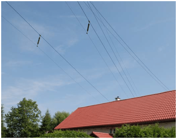
Near Wałbrzych, a technical solution was implemented that involves additional shielding conductors located below the lowest working overhead lines at a sufficient distance to provide electrical insulation. Typical 110 kV long-rod insulators were used for the installation of shielding conductors (model: LP75 / 31). The shielding cables are galvanically connected to both support structures, which, regardless of the electrical induction, provides the potential of the earth along the entire length of the additional conductor (Fig. 1). As can be seen, under the overhead line there are residential and commercial buildings, causing permanent exposure of the residents to the electromagnetic field generated by the working overhead power line. The solution used in the span reduces the electrical component of the electromagnetic field. Investigation of the effects of the use of such a method of altering the field distribution is particularly interesting with regard to limiting the maximum field strength and the width of the impact area underneath the overhead line where the electric field strength would otherwise exceed 1 kV/m [5]. Distribution of the electric field was calculated for the two cases:
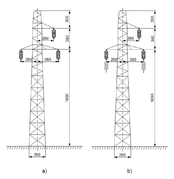
• Typical 110 kV overhead line variant without the shielding cables (Fig. 2a)
• Actual 110 kV overhead line variant with shielding cables (Fig. 2b)
Technical specifications of the 110 kV line:
• AFL-6 240mm2 working wire (tension=90MPa, g=0.0336, d=21.7mm)
• overhead ground wire type O/FL 70mm2 (tension=120MPa, g=0.077, d=11mm)
• B2 type pylon
• Length of the span L=140m
• sag of overhead working wire f=1.03m
• length of insulator HI=1.8m type LP75/31
The figure (Fig. 2a) shows the overhead straight-line support pylon type B2 of the overhead line 110 kV and the basic geometrical dimensions of the support structures and the location of additional grounded shielding wires (Fig. 2b). Computational identification of the electric field distribution was performed at the centre of the span, i.e., where the distance of the phase conductors from the ground is the smallest, for a distance of up to 25m to the either side of the overhead line. It is known to be the most unfavourable case in which, for a given span, the intensity of the electrical field generated by the power line reaches the highest values. Among the commonly used methods to determine the distribution of the electric field in the surroundings of various power infrastructure facilities, the authors focused on the use of the finite element method, which by its nature gives an approximate solution, but allows for the computational identification of objects of any atypical structure and/or geometry [6].
Analysis of distribution of the electric fields
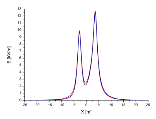
At the height of h=2m above the ground level the electric field intensity determined on the basis of digital simulations does not exceed 1 kV/m at any point. Therefore, according to the Regulation of the Polish Minister of Environment [1] it is possible for people to remain in the area for extended periods of time. As shown in the figure (Fig. 3), screening shielding further improves the effect, causing a decrease in the field intensity at each point of the tested area.

As the overhead lines run directly above the residential building, it is worth checking whether the occupants of higher floors or open terraces are not exposed to an electric field exceeding 1 kV/m. The results of the second digital simulation of the electric field distribution at the height of the ridge h=8m are presented in the figure (Fig. 4). As can be seen if no additional grounded wires were attached under the two lower working lines of the overhead line, the resulting electric field intensity would slightly exceed the permissible value at E=1.36kV/m.
With the grounded shielding cables, the intensity of the electric field was reduced considerably at the height of h=8m below the limit value [1] at a maximum of E=0.89 kV/m.

Analysis of the electric field intensity in between the additional grounded wires and the lowest phase wires shows a significant change in the electric field intensity.
This is the expected effect as the entire drop of the potential from the full potential of the phase conductor to zero ground potential must then occur over a much shorter distance than in the case of power line with no additional earthed shielding conductors. For this reason, the capacitance to earth of the line increases, which in turn directly affects the amount of transmission losses occurring during the transport of energy [5].
In addition, it is easy to see that in the considered space the use of additional shielding conductors located below the lower phase conductors has little effect on the spatial distribution of electric field intensity as well as on the maximum values that are significant and may exceed E = 12 kV/m.

For the heights above the overhead ground wire, the electric field distributions for the both 110 kV overhead line span designs do not differ significantly. The overhead ground wire introduces the ground zero potential to the analysed system, and thus changes the distribution of electric field lines. Due its location, the overhead ground wire strongly influences the value of electric field intensity in the height range above the overhead line support structures.
Table 1. Intensity of electric fields calculated for selected heights for power line without shielding wires.
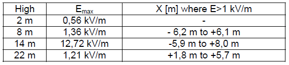
Table 1 shows the maximum intensity of electric fields and the width of terrain (in meter) where the electric fields intensity is greater than 1 kV/m calculated for selected heights for power line without shielding wires.
Table 2. Intensity of electric fields calculated for selected heights for power line with shielding wires.
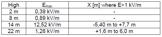
Table 2 shows the maximum intensity of electric fields and the width of terrain (in meter) where the electric fields intensity is greater than 1 kV/m calculated for selected highs for power line with shielding wires.
Conclusions
1. The use of additional grounded components located between the working cables and the ground allows the reduction of the resultant electric field recorded in the tested strip perpendicular to the axis of the power line calculated for the height of 2m.
2. The use of additional grounded components located between the working cables and the ground causes a strong local variation in the distribution of electric field lines in this height range. This may be related to the increase of the capacitance to earth of the overhead line and, consequently, to the increase in transmission losses in the section affected by the use of additional shielding cables.
3. Planned geometrical configuration of the work wires and grounded wires allows to shape the resultant distribution of the electric field generated by the overhead power line.
REFERENCES
[1] Rozporządzenie Ministra Środowiska z dnia 30 października 2003 r. „W sprawie dopuszczalnych poziomów pól elektromagnetycznych w środowisku oraz sposobów sprawdzania dotrzymania tych poziomów”, Dziennik Ustaw nr 192, poz. 1883, 2003.
[2] Szuba M. [i inni], „Linie i stacje elektroenergetyczne w środowisku człowieka” (Wydanie 4), Biuro Konsultingowo- Menadżerskie EKO-MARK, Warszawa 2008.
[3] Zeńczak M., „Analiza pola elektrycznego i magnetycznego wokół linii elektroenergetycznych i wybranych urządzeń elektroenergetycznych”, Napędy i Sterowanie Nr 9 2001.
[4] Zeńczak M., “Estimation of electric and magnetic field intensities under power transmission lines in real country conditions”, Przegląd Elektrotechniczny Nr 7 2008.
[5] Zeńczak M., “Analiza technicznych problemów związanych z dozymetrią pól elektromagnetycznych o częstotliwości przemysłowej”, Prace Naukowe Politechniki Szczecińskiej, Szczecin 1998.
[6] Sadiku M. NO, “Numerical techniques in electromagnetics”, Second Edition, CRC Press, LLC Boca Raton London, New York, Washington 2001.
Authors: mgr. inż. Jacek Gumiela, Politechnika Wrocławska, Katedra Energoelektryki, ul. Wybrzeże Wyspiańskiego 27, 50-370 Wrocław, E-mail: jacek.gumiela@pwr.edu.pl; dr Dariusz Sztafrowski, Katedra Energoelektryki, ul. Wybrzeże Wyspiańskiego 27, 50-370 Wrocław, E-mail: dariusz.sztafrowski@pwr.edu.pl.
Source & Publisher Item Identifier: PRZEGLĄD ELEKTROTECHNICZNY, ISSN 0033-2097, R. 94 NR 3/2018. doi:10.15199/48.2018.03.32
