Published by Adam SZELĄG, Tadeusz MACIOŁEK, Politechnika Warszawska, Instytut Maszyn Elektrycznych
Abstract. A 3 kV DC supply system, used on railways in Poland, since 1936, has power delivery capacity that allows reaching by trains a maximum speed of 250 km/h. Currently, the maximum trains service speed on Polish railway is 160 km/h, although speed record reached in 1994 was 250,1km.Therefore, it is worth modernising the system to increase power demand of trains with speeds 200-220 km/h, which will start service in year 2014. It requires application of proper methods to find compromise between the required effectiveness and the cost of the investments. The paper presents a system approach for analysis and synthesis of the 3 kV DC supply system used in a process of feasibility studies including a concept and a preliminary design.
Streszczenie. Stosowany na kolei w Polsce od 1936 r. system zasilania 3 kV DC pozwala na zasilanie pociągów osiągających maksymalne prędkości 250 km/h. Obecnie maksymalna prędkość pociągów na kolei w Polsce nie przekracza 160 km/h, aczkolwiek rekord prędkości osiągnięty w Polsce w 1994 r. wyniósł 250,1 km/h. Dlatego istotne jest, aby przeprowadzić modernizację zasilania trakcyjnego dla zapewnienia wymaganej energii dla pociągów o prędkościach 200-220 km/h, które pojawią się w 2014 r. Wymaga to zastosowania odpowiednich metod, aby uzyskać kompromis pomiędzy wymaganą efektywnością zasilania a kosztem inwestycji. W artykule przedstawione jest systemowe podejście do zagadnień analizy i syntezy stosowanych w procesie projektowania trakcyjnego układu zasilania, 3 kV DC w projektach koncepcyjnych i wstępnych dla celów studiów wykonalności (Modernizacja systemu zasilania trakcji elektrycznej 3 kV DC dla zwiększonego poboru energii pociągów o podwyższonej prędkości jazdy – zagadnienia analizy i syntezy)
Keywords: electric traction system, system analysis, modelling and simulation, power demand.
Słowa kluczowe: system trakcji elektrycznej, analiza systemowa, modelowanie i symulacja, zapotrzebowanie na energię.
1. Introduction
Last year plans of construction of the so-called Y high speed railway line with maximum speed over 300 km/h with 2×25 kV 50 Hz power supply, postponed by the Polish Government, caused that focus has been put back at the 3 kV DC traction power supply system which has been used in Poland since 1936, but its power delivery capacity has not been reached. So it is worth analysing how it is possible to maximise usage of 3 kV DC system electrical energy delivery capacity for the increasing power demand and speed of trains over 200 km/h, even up to 250 km/h as it is applied in Italy at Dirretissima railway line [2]. A system analysis makes a useful tool for preliminary study and a concept design of an electrified transport system.
List of the used symbols:
ETS – electric traction system
PSN – AC power supply network,
TPSS – traction power supply system,
ETV – electric traction vehicle,
TS – traction substation
2. Electric transport system
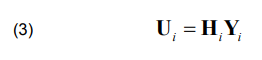
Elements of both the analysis and synthesis appear in the examination of issues and phenomena related to the functioning of the ETS. Therefore, methods with application of ETS subsystems models and their implementation, which allow the introduction of elements of the analysis – e.g., determination of a group of functional parameters of ETS power supply have been developed as [2, 4, 5, 6] substations load, catenary, voltage drops, efficiency, consumption and energy loss, etc. including: environmental conditions on the basis of the input parameters (characteristics) of the system. These include: distances between substations, types of rectifier units installed in the traction substations, catenary sections, the parameters of the electrical power engineering system. Other specified functional parameters are as follows: defined traffic, types of trains, locomotives, time-table with consideration of the technical limitations imposed on the ETS (technical criteria and reliability, the impact of ETS on the surrounding technical infrastructure and the environment – harmonics, voltage fluctuations, and stray currents). Dynamic model of the ETS system can be presented in the generalized manner in shape of a set of equations describing the respective subsystems [3,4,7] (Fig. 1):
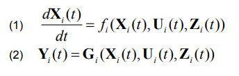
where: i=1,..,5
and structural equations:
where: Xi (t) – vector of state variable of ith subsystem, Yi (t) – output vector of ith subsystem, Ui (t) – control (input) vector of ith subsystem, Zi (t) – vector of disturbances of ith subsystem, Hi – structural matrix.
Dimensions of the matrix structural equations Hi depend on the number and types of ETVs moving along the railway line, the TPPS system and number of traction substations TS as well as their scheme of supply from the power system [1,4,6].
Elements of the analysis will also appear: when evaluating the possibility of maintenance of the existing supply system in the conditions of masses and train speed growth and the introduction of new locomotives with higher power,
– when determining the degree of utilisation of the existing devices installed in the supply system (the use of installed power), the load of wires and rectifier units of traction substations, energy transmission efficiency and power quality,
– when solving problems of compatibility of subsystems (electrical engineering power supply – traction supply system – traction vehicles – control and signalling systems) and electrical devices.
Elements of synthesis involve:
– selection and configuration of DC and AC power supply system (installed power, cross sections of wires, distances, supply voltage at AC side of PSN),
– selection of locomotives proper for a category of trains (mass and speed) for a specified line, based on the requirements for the functioning of ETS (traffic forecast) with consideration of limitations arising from the need of fulfilling the technical criteria (international and national standards and regulations) as well as reduction of distortions introduced by the ETS to the surrounding environment.
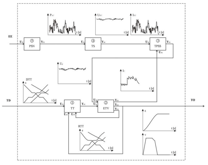
Fig. 1 Functional scheme of ETS system after decomposition into subsystems and presentation of exemplary time runs (time axis scaled in seconds) of input and output values (TT – time-table; DTT – demanded time-table, RTT – actual (resulted) time-table ,TD – transport demand, TO – transport output; Ic- ETV’s current, Up-voltage in catenary, IDC – TS’s current, UDC – voltage at TS’s busbard, PAC – power taken by TS from PSN).
Due to the fact that the issue of synthesis usually cannot be solved explicitly, some additional criteria are being introduced:
– maximising utilisation of the installed devices power,
– to provide reserve in a case of emergency,
– possibility of overcoming speed reductions by trains with occurrence of traffic disturbances,
– the system’s openness to changes in the traffic volume (the possibility of staging the development of ETS supply system with increase of energy demands from ETVs and maximising the use of existing infrastructure (optimal adaptation of ETS infrastructure for the transport forecast),
– minimisation of energy transmission losses
Combining elements of the analysis and synthesis of ETS results in a complex problem, which will deal with the selection of ETS elements and determination of their parameters (rated power, overload, sections, etc.) and their mutual dependencies (e.g. voltage at the ETV’s collector functioning as dependence between TPSS and ETV or changes of traction substation load giving an influence on PSN, similarly changes of voltage in the PSN have the impact on the operation of traction substation).This refers to the exploited (manufactured) devices as well as to defining the requirements for implementation of new measures due to the defined demand for transport (traffic forecast- traffic flow TD and the resulting demand for electrical energy EE (Fig. 1), functional requirements – quality and reliability of supply, and the interaction between different ETS’s subsystems as well as between ETS and the environment.
In developing new methods for analysis and system design with respect to exploited lines as well as newly constructed, it must be assumed that in principle one is dealing with a complex problem, which combines elements of both synthesis and analysis. All the assumptions made at the stage of analysis of functioning conditions of the existing ETS as well as design of new lines or improvement actions e.g.:
-aiming at: – rationalisation of energy consumption or effective energy consumption (improvement of its usage),
-introduction of a new stock or changes in traffic,
-introduction of new control systems
must take into account existing state of ETS, its parameters and functional requirements. Therefore, all the actions (as forecasts) oriented towards improvements (as increasing efficiency) should result from the analysis of the existing state and then on the basis of results of such an analysis, by application of assumed technical criteria (e.g. rationalising the energy consumption, maintaining the distortion level at permissible limits) lead to changes (choice of modernisation option-elements of synthesis), which will improve or even enable the operation of a system.
Fig. 2a,b Graphs showing exemplary changes of energy delivery capacity of ETS (obtained by modernisation stages M1 and M2 of the existing TPSS of the ETS’s) versus time due to increase of demand for energy (blue broken lines) by transport means. Please observe reduction of the energy delivery capacity (RE1<E1, RE2<E2) of TPS during the modernisation processes, which will force reduction of traffic (RE1<D1 during M1; RE2<D2 during M2).b.) modernisation undertaken early enough with lower reduction of capacity (t1 in Fig.2b < t1 in Fig. 2a and RE1 in Fig 2a < RE1 in Fig. 2b) to get the required energy delivery capacity E1 to E3 high enough above the energy demand D1 before its increase to D2 due to traffic increase.
3. Application of a system analysis in the ETS.
The analysis of the ETS system as a research method is used when the situation occurs, in which the state of the system is currently or will in future be unsatisfactory, and it can be anticipated that the actions (modernisation) may improve the situation significantly (Fig. 2). After the analysis we obtain the system description of the situation, as well as courses of action, which will produce positive effects.
The results of such an analysis may be used by policy ma-kers to choose the most advantageous solution due to the certain criteria. In addition, a system analysis allows for the justification of purpose of the selected variant against pressures from the side of interest groups and against the wrong interpretation of the phenomena. It is a crucial factor because the results may have significant influence on the range and cost of the infrastructure modernisation.
The results obtained from the analysis of the system also allow reference to the unexpected events or disturbances in the functioning of the system.
In Fig 2a there is shown time-varying demand for energy used by moving ETVs and effectiveness (energy delivery capacity) of TPSS. Application of a system analysis to ETS allows assessing effectiveness of ETS when increase of demand for energy due to changes in traffic is expected (from D1 to D2). When the effectiveness E1 (energy delivery capacity of the ETS) is becoming close to the energy demand (time point t1) implementation of improvement processes – modernisation is to be started – point A (period of modernisation M1 between t1 and t2 – points A-B, period t4–t5, M2-points C-D). Effectiveness of ETS during modernisations M1 and M2 energy delivery capacity is reduced (for modernisation period M1 – effectiveness RE1 between points B-C and RE2 during M2 – between points C-D) as well as change of demanded energy delivery due to change of traffic (increase from D1 to D2).
As example we could assume the existing two-track ETS with 3 kV DC supply and a bilateral supply scheme with traction cabin TC in the mid-points between neighbouring traction substations TS – fig.3a. As a measure to enhance the energy delivery capacity of ETS, after application of the system analysis, the improvement of ETS to by process of modernisation M1 is undertaken. It may be, for instance, construction of new traction substations in positions of traction cabins (Fig. 3b). This will enhance the effectiveness of the ETS above the increasing demand D (period t2-t4). And again, when as a result of the system analysis it was predicted, that additional modernisation M2 of the ETS is required; a construction of traction cabins TC between traction substations may be done (Fig. 3c). It could slightly improve the effectiveness of the 3 kV DC ETS above the energy demand level (Fig. 2a).
In order to maintain the energy capacity proper for energy delivery even during the modernisation process it is required to start it before the demand will be increased and assure that during the process of the modernisation power capacity will be high enough (Fig. 2b).
System analysis of the assumptions is not conducted for a particular decision maker, but in most cases, the decision maker orders such an analysis so to obtain as much information for undertaking a decision as it is possible. The result should include all the possible consequences of any line of conduct. The analyst should clearly establish the expectations of the decision maker, outline possible alternatives, consider consequences of each option, and then arrange them accordingly to selected criteria. In practice, decisions are not always proceed with accordance to such a scheme, but if it deviates from such a scheme, it occurs only to a minor extent. System analysis related to ETS should also be based on this scheme. To achieve the objectives (such as reduction of electricity consumption by railway vehicles, an increase in average driving speed, reduction of the amount of emergency on the railways, etc.) set by the decision maker, one creates different types of solution variants (e.g. reconstruction of the supplying substation, changes in the profile line, change of traffic, etc.).
To explore the various options, models that can be used to assess the effects of the variant or the cost of its implementation are created. Specifically the cost, effectiveness and feasibility of the option are the important factors [8,9,10].
For different variants may emerge the need to use different models. The use of different models may be necessary to prioritise the options for different purposes. The analysis should end with a rearrangement of variants and be presented to the decision maker together with the effects of each variant. In the majority of issues related to ETS, factors affecting the results are considerable and their mutual relations rather complex. Such a situation causes that intuitive approach will often lead to erroneous and costly solutions. Application of coupled models, in mathematical terms, is necessary for the appropriate formulation of description of ETS functioning and analysis of its operation in different variants of solutions.
4. Procedure for an ETS system analysis
Finding the solution for the improvement of the existing state or choosing the best target variant requires knowledge and clarification, as careful as possible, the aims of decision maker. On such account, one should determine options to achieve these objectives. A further step is to rank the possible options. Implementation of such a procedure will generate further questions. In order to determine the possible variants to achieve, it is not sufficient to be aware of goals, but also to know the area in which the decision maker has the freedom of action. For the ranking or comparison of variants, one may need to anticipate the consequences that will result from implementation of each variant (also those that do not link directly to the realisation of goals). Determination of the consequences of each option requires the use of an appropriate cause-effect model, which will allow the decision maker to indicate the consequences of the choice of a particular variant. Such a model should also take into account the uncertainty of future conditions, such as changes of external conditions other than those assumed in the analysis.
In extreme cases, the variants may differ considerably among themselves, because in principle the implementation of a goal is possible through different ways of proceeding. In such situation it may be necessary to apply various models for different groups of variants. It can be also justified to use models of different degree of specificity depending on the analysis of a state. Main steps of system analysis include:
Main steps of system analysis include:
a) formulation of a problem taking into account assumed goals,
b.) defining and working out the variants,
c.) selection of variants on the basis of constraints,
d.) development of forecasted situations ,
e.) construction of models,
f.) application of models for foreseeing effects,
g.) comparison and ranking of the obtained variants.
Analysis of the results or a preliminary version of final results may lead to a modification of the previous assumptions.
Typical interactive loops that occur are following:
a) improvement options loops, in which occur a modification of parameters in various options for attainment options preferably pursuing the goals; in some cases this process can be implemented by means of optimisation procedures;
b) problem formulation loops, in which on the basis of the results of an analysis the modification of goals is performed;
c) analysis of restrictions loops, in which it is, evaluated how, changes of restrictions influence the degree of goal accomplishment;
d) loops of tuning (adjusting) models, in which particular elements of models or complete models are either simplified, for the purpose of attaining less specific but more certain decisions, or detailed so as to emphasis the more important characteristics of variants.
Furthermore, if one considers that the process of implementation of the selected option may be too long, it must be accounted that the actual conditions, in which the variant is carried out, may differ from those assumed at the stage of analysis. In such case, refinement of options for changeable conditions – during the process of implementtation and if it is possible – correction of a project, can be applied. At each stage of the system analysis contacts of an analyst with a decision maker (or contracting the project) are of high importance. The original formulation of the problem is never exhaustive and does not include the whole spectrum of situations. The results of the analysis have an impact only on the initial view regarding the solutions. Both the goals and the restrictions can be modified during the process of analysis, and the considered time horizons may be a subject to changes.
5. Formulation the problem
Formulation of the problem includes:
-identification of the tasks to be solved,
-determination of the scope of the solutions for these tasks,
-clarification of the objectives,
-determination of what devices and to what extent may the proposed solutions affect,
-initial proposal for the approach to the analysis
Stage of formulation of the problem should give an initial indication of the purpose and if possible, identify the objectives in a quantitative manner, identify preliminary alternatives for analysis, lead to the definition of restrictions and a determination of the expected effects. Formulation of the problem is therefore a very important step, because its correct implementation allows the determination of whether the problem is artificial or trivial, and also provides a framework in which one can move through the later stages of analysis. Difficulties encountered during the formulation of the problem:
a) the interrelations of the subsystems – changes in one subsystem affect other subsystems and assessment of impacts of the performed actions in interrelated objectives, constraints and consequences for the individual subsystems is difficult to conduct;
b) the difficulty of determining the goals, without the approximate values of the effects, which will result from the introduction of options, it is difficult to define precisely the objectives;
c.) lack of clear criteria for selection, the decision maker preferences may be difficult to define, and they may change within time.
Therefore, this step should be the object of application of a system analysis.
The goal, which designates the decision maker (e.g. ETS operator) to be achieved, can be declared in a more or less detailed manner (“energy efficiency”), and can also be defined in quantitative terms (e.g. “to reduce traction energy consumption by 10%”, “to reduce transmission losses on the DC network by 20%“,” to reduce demanded peak power by 5%”, etc.).
The decision maker may seek to achieve different objectives. Sometimes the decision maker gives only the most important goals while an analyst (project contractor) must be aware of the possibility of unspecified purposes or purposes given in the form of restrictions. Usually, while solving issues the decision maker determines several goals, among which there are competing goals, that is, that the improvement in one of these objectives leads to deterioration in other aspects (e.g. efforts to reduce losses increase requirements for installed power, which in turn increases the idle losses of transformers). In this case, one should use the following approach:
a) determine the sequence of objectives;
b) identify the most important goal;
c) all the objectives should be transformed into restrictions and one should seek solutions possible to be implemented,
d) establish evaluative system by ranking goals.
With the overall goal of rationalization of energy consumption on the railways, the decision maker may also have other objectives: to increase the average speed of selected categories of trains, improve comfort, increase safety on the railway lines, improve punctuality, and reduce failure rates. Some of these goals are competitive, while other can be achieved in the same ways of implementation (e.g., by reducing gradient of track energy consumption for traction purposes is reduced and also the ride comfort is increased).
To evaluate the analysed options one should have a measure value of the effects, which are brought by each of variant. Some of the results are easy to estimate numerically, while other – the more abstract – are not. The efficiency of the power system, the maximum power demand or the global energy consumption on the railway line can be written in the form of numbers, and parameters such as: ride comfort requires preparation of tools to describe this rather abstract and ambiguous concept (e.g., through the application of special tariffs for journeys with a high standard of the offered transport service).To compare the options it is not enough to describe the quantitative results obtained in each of them. One should use the criteria enabling the proper ranking of the options.
However, since there are often not universal, objective criteria for sorting options, so in each individual case, such criteria should be established, mainly on the account of the value scaled by the decision maker. Using these criteria, one can also take into consideration the opinion of external factors, which will be influenced by the effects resulting from the implementation of a given variant.
During the formulation of the problem one must also specify the area of restrictions. They may arise from the physical properties of the analysed systems (e.g. power capacity of the supply), but also from the accepted standards (e.g. level of voltage in catenary) or imposed require-mints (e.g. density of traffic or maximum power of trains). These variants, which are not prohibited by the restrictions (do not meet the criteria) are called permissible or attainable.
Some restrictions are permanent and can never be exceeded (e.g. cross-section of catenary due to applied type of support structures), some may change over time (as increase of power capacity due to investments in power supply system) and due to the change in requirements (e.g. change in assumed time-table and type of locomotives), and some are imposed by the top-down decisions. For the restrictions that could be alleviated (e.g. density of traffic), the analyst should carry out the consideration of how such alleviation would affect the achievement of the objectives (e.g. lower density of traffic may require bigger mass of trains), and what would be costs of such restrictions reduction.
In the analysis of the phenomena occurring in the ETS, the restrictions may include: technical parameters of the vehicles and the supply system, speed limits on the sections of the line, minimum voltage at the pantographs of trains. A restriction may also constitute a lack of opportunity of location traction substations at the specific point of the ETS or change in the type of catenary or lack of possibility to implement a freely shaped time-table.
6. Creation and selection of variants
Variants taken into consideration during a system analysis can vary considerably. They do not have to constitute their substitutes and do not have to assure the performance of the same functions.
The initial stage of variants’ creation should com-prise all the possible ways of proceeding, so giving at least partial chances for the accomplishment of objectives. In the set of analysed variants, usually the so called „zero” (do nothing) option is included. This variant is mainly used for comparative purposes (as a ‘reference option’).
Usually during the analysis of the selected variants occur new variants, which at the beginning have not been known to the both analyst and decision maker.
For the purpose of an exemplary task of rationalisation of energy consumption of ETS, a range of creation of diverse variants may be wide. This may include: changes in time schedule, rolling stock replacement, reconstruction of the supply system or even the reconstruction of the whole line (e.g. alleviation of the route profile). Each of the variants can to various extent influence the achievement of a goal and costs of their implementation are also diverse. For these or even other methods aiming at reduction of energy consumption on railway lines, it is possible to create a huge amount of options to be considered. Since the number of variants that have been generated at the beginning of the analysis may be large, they should undergo a pre-selection. Many variants can be rejected at the outset, because they do not comply with the restrictions. This can be observed using very simplified models, which give approximate results. In this manner, variants that are worse than others, at least in one aspect and in other aspects no better than remaining options can be eliminated.
Further stages should be conducted on detailed models with respect to quantitative parameters. The last stage of the ETS analysis should, in a possibly full and accurate manner, describe the processes occurring after the implementation of various options, so as the decision maker knows the extent to which each of they pursue goals and what are the further effects. At this stage one can enter the optimisation procedures. Multi-criteria optimising algorithm can be applied with usage of a scalarization approach and a goal function or penalty function defined for the optimisation algorithm.
Since the parameters, on which we have the influence, usually do not change continuously (e.g. it is impossible to select smoothly the cross-section of catenary, power supply and transformers parameters, numbers and parameters of rectifier units) the number of possible variants is significantly narrowed and the search for global analytical solution is not justified. In that case it is possible to use any of the random algorithms.
To anticipate the effects of the implementation of different options it is necessary to use system models. It is most preferable when models are formalized and written in a mathematical form. On the basis of such models one can develop the computer implementation of models in order to conduct the simulation tests.
Analysed variants may differ among sets of data assumed. Set of data regarding the state of environment can be taken as constant (when these parameters are strictly defined) or variable (when there is uncertainty about these parameters). In the latter case, it is recommended to conduct a sensitivity analysis of the effects of variants on the changes of the environment state so as to assess the uncertainty of achieving the objectives for each of the variants.
An exemplary division of the electrified railway line parameters at the design stage of this line can be a division into: independent (top-down set)-the size of transport and into dependent (those we have an influence on) -technical parameters of a supply system (to meet the technical criteria for the implementation of the given traffic flow) or organisation of train schedules at a given transport demand.
Obviously, for the proper construction of models it is not enough to know the general form of mathematical equations describing the analysed system as they should be verified and tuned to the actual conditions.
7. Range of applications of modelling and simulation techniques in the ETS
The range of applications of computerised techniques to area of ETS may be enlisted to one of the following groups, due to:
a.) CAD (computer-aided design) during planning stage of the ETS, its subsystems and components,
b.) analysis strategy of operation of the ETS – design of timetables, traffic control, centralised and decentralised control and management of the ETS,
c.)for design of operational service and control system, operational, control, surveillance and decision supporting systems-e.g. methods of optimisation of ETVs motion and operation of TPSS with regard to energy consumption,
d.) the use of specialised software for ETS simulations during steady and dynamic states – for the analyses of supply system loads, main circuits of electric traction vehicles, control and signalisation systems, mutual interactions between subsystems (ETVs-TPSS; high power circuits-track circuits, etc.) and electromagnetic fields- in the range of distorting inference of the ETS and its influence on the surrounding environment and technical infrastructure.
Due to the complexity and multi-aspect nature of phenomena as well as available technical devices, methods of the analysis and design are oriented at considering certain types of problems as:
a.) energy problems (delivered power, energy consumption, energy losses etc.), regarding the phenomena occurring at electrical steady states in AC and DC circuits; for the analysis of such problems it is sufficient to use static models considering the average and equivalent values, such as peak, average and equivalent power and currents of load or stray currents flow ,
b.) electromechanical aspects – concerning both motion and power collection by the ETVs as well as resultant TPSS load, which is associated with energy problems. The mutual interaction of TPSS and ETVs should be taken into account, due to the influence of voltage in a catenary on motiontraction parameters of the ETVs (dependence of voltage in catenary on the ETV’s traction characteristics). The derived models should incorporate dynamics of load changes of TPSS and ETVs motion. Therefore, they have nature of dynamic models (with regard to phenomena of ETVs electromechanical constants values in range of tens of seconds), in which during the analysis of state of the ETS system at the given time step, the ETS state at the previous step is taken into account.
c.) electromagnetic problems and transient states– occurring in much shorter time than the phenomena of electromechanical type (b), which requires the development of models for analysis of the fast-changing phenomena (such as short circuit, overvoltage, transients) and analysis time runs for the content of the component variables (including harmonics) and the resulting ability to assess interferences introduced by ETS to the surrounding technical infrastructure.
d.) problems with traffic and transport management (for set volume of transport, traffic structure, types, masses, train speed). For each group of problems a)-d.) equations take a specific form, thus in the following project, emphasis was put on the proper selection of models for the problem under consideration.
Proper functioning of the ETS is conditioned by, apart from fulfilment of functional requirements (realisation of transport tasks), an attempt to redeem technical requirements and constraints regarding e.g. capacity of energy transmission by TPSS to ETV (groups a. and b.), but also the proper cooperation with both surrounding technical infrastructure and environment.
In case of negative assessment in the analysis with application of models from group c), ETS given variant, even if it turns out to be optimal because of other criteria (e.g. energy consumption) should be rejected as not meeting the basic technical conditions. Solving the subproblems of the system operation may be impaired due to the interferences Z (Fig.1.) occurring in any subsystem (as disruption of traffic organisation, power supply system breakdown, short circuit in the catenary, damage to rolling stock, unplanned slowdown etc.). Therefore, the main task is to maintain the proper functioning of the system even under conditions of interference and the possibility of transition to a state of normal operation (e.g. traffic congestion release, catch up the delay) at the lowest cost (power consumption).

To ensure the functioning of the system in conditions of distortions it is necessary to introduce certain breakdown restrictions in the description of a system operation. These restrictions will depend on the type of corrective actions (improvements) to be taken in case of failure. This approach sometimes requires an algorithm with conditional instructions, the automatic decision-making methodology performed by the simulation program (elements of artificial intelligence) or by the operator from the outside (stop of the program and the need to take a decision on the selection of an algorithm of further simulation or changes in assumptions).
In situation when in the program there are various algorithms of proceeding and choice of solutions, which support the work of operator, in case of a need for intervention, one can speak about elements of an expert system (decision-making support). Such a comprehensive approach to problem analysis and design ETS – selection of technical solutions required to deliver the overarching goal: supply of adequate quantities of electricity of a certain quality parameters to ETV, performing the set transport constitutes a fundamental assumption with respect to the formulation and the required structure of the ETS model system and its subsystems.
Conclusions
The necessity of development and modification of classical methods, established long time ago and used in the analysis and design of ETS ensures from the fact that there was, especially in the country, synthesis approach to issues that takes into account not only the complexity of electrical and mechanical phenomena occurring in the STE but also specificity resulting from local conditions in Poland (such as significantly lower than in other countries which use the 3kV DC power supply options for the ETV because of the large voltage drop in the supply system) and the interaction between the subsystems. An important feature is a combination of a simulation package with blocks of postprocessors analysis, which allows the support of system functioning evaluation (the comparison of set up and executed timetables, meeting the technical criteria, efficiency, energy consumption per unit, introduced distortions, etc). Due to the significance of such issues as compatibility of electrical subsystems and environmental impact as well as energy-electromechanical orientation of developed simulation software, results obtained with the help of programs for ETV’s motion simulation can be supplemented with the use of simulations developed in the course of these project models of ETS subsystems. They are designed for analysis of issues as: interference from higher harmonics, voltage fluctuations or transients in power supply or disturbance emission. This allows for conduction of detailed simulation studies on selected, identified as critical elements for the functioning of ETS conditions of cooperation of selected subsystems in transient states (short-circuit, overvoltages in TPSS and the possible to occur interferences between subsystems TPSSETV and impacts on traffic control circuits. Voltage at the pantograph of the locomotive influences the power developed by the traction drive according to its traction characteristic. It is defined by EN 50-338 standard. In order to put into service with maximum speed above 200 km/h on CMK railway line train sets with nominal power up and above to 6 MW it is required to enhance its traction power supply system. During the performed studies [7] a set of analyses has been performed for different time-tables and variants of operation of the power supply system. The main aim was to find the effective solution to modernise the power supply system to the stage allowing obtaining the required speed with utilisation of the installed on board of vehicles power.
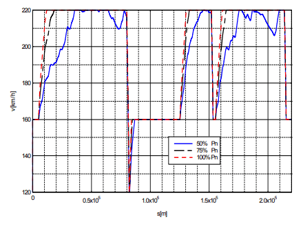
In Fig. 4 there are presented results of simulation of a 426 t train-set with maximum speed of 220 km/h – a theoretical run on a section of track with speed restrictions. – speed “v” versus position of the train. It may be observed influence of the available power (100%, 75% and 50% of nominal power Pn = 5,5 MW) on traction parameters of the train – specifically opportunity of acceleration (as route sections 10000 to 30000 or 165000 m) in a region of higher speeds (above 180 km/h) or maintaining maximum speed, when gradient is increasing (as sections 65000 to 75000 or 195000 to 205000 m). A system analysis with application of the described in the paper method has been worked-out in order to receive the effective power supply system for a defined traffic forecast. It appeared, as a result of the analysis, that it is required to construct additional traction substations TS in locations of traction cabins TC (migration from a scheme 3 a. to 3 b.) in areas, where the power capacity of the supply 3 kV DC system and trains power demand by trains were not balanced with high enough level of voltage in catenary
REFERENCES
[1] Arrillaga J., Smith B. – AC-DC Power System Analysis. IEE London, 1998
[2] Capasso A., Buffarini G.G., Morelli V., Lamedica R. – Supply system characteristics and harmonic penetration studies of the new high speed FS railway line Milan-Rome-Naples. IEE Int. Conference on Main Line Railway Electrification, York (UK), 1989
[3.] Kaczorek T. Teoria wielowymiarowych układów dynamicznych liniowych. WNT, W-wa, 1983.
[4.] Lewandowski M. -A Analiza zjawisk elektromechanicznych w szynowym pojeździe trakcyjnym z uwzględnieniem zmian współczynnika przyczepności kół napędowych Zeszyt “Elektryka” nr 139, OWPW, 2009
[5]. Mincardi R., Savio S., Sciutto G. – Models and tools for simulation and analysis of metrorail transit systems. COMPRAIL’94- Computers in Railways – Fourth Int. Conference on Computer Aided Design, Manufacture and Operation in the Railway and Other Mass Transit Systems, Rome, 7-9 September, 1994
[6] Szeląg A., Mierzejewski L. – Ground transportation systems. (in: The Encyclopedia of Electrical and Electronic Engineering. Volume: Suplement I, John Wiley &Sons, Inc., NY, USA ,2000)
[7] Szeląg A.- Zagadnienia analizy i projektowania systemu trakcji elektrycznej prądu stałego z zastosowaniem technik modelowania i symulacji. Prace Naukowe PW, Seria ELEKTRYKA, s. 178, z. 123, 2002
[7] Szeląg A., Maciołek T., Drążek Z., Patoka M., Urban A., Załuska Z. at all– Ekspertyza dotycząca układu zasilania sieci trakcyjnej linii CMK, praca na zlecenie PKP Energetyka S.A., 2012 (not published)
[8]. PHARE Project no PL 9309/0203 „Power Supply Study for E-20 Railway Line Kunowice-Warsaw section” (ITALFERR, Włochy, Politechnika Warszawska) (not published)
[9] EC Project UserGroup and InfoBank to support rail interoperability. GMA2-2000 32015 Projekt Badawczy V-tego Ramowego Programu Unii Europejskiej. 2002-2003
[10] Projekt EUROPEAID/112846/D/SV/SI, Pomoc Techni-czna we wdrożeniu systemu GSM-R,ERTMS/ETCS i zdalnego sterowania urządzeniami stałymi systemu trakcji elektrycznej sieci kolejowej Kolei Słoweńskich. (Kolprojekt, Holland Railconsult, Austrokonsult, Omegaconsult), 2003 (not published)
dr hab. inż. Adam Szeląg, doc. dr inż. Tadeusz Maciołek Politechnika Warszawska, Instytut Maszyn Elektrycznych, Plac Politechniki 1, 00-661 Warszawa, E-mail Adam.Szelag@ee.pw.edu.pl; Tadeusz.Maciolek@ee.pw.edu.pl
Source & Publisher Item Identifier: PRZEGLĄD ELEKTROTECHNICZNY, ISSN 0033-2097, R. 89 NR 3a/2013
