Published by Electrotek Concepts, Inc., PQSoft Case Study: Low Voltage Harmonic Filter Design, Document ID: PQS0304, Date: January 10, 2003.
Abstract: The industrial harmonic problem can be solved using a comprehensive approach including site surveys, harmonic measurements, and computer simulations.
When mitigation of harmonic distortion is required, one of the options is to apply a filter at the source of harmonics, or at a location where the harmonic currents can be effectively removed from the system. The most cost effective filter is generally a single-tuned passive filter and this will be applicable for the majority of cases. Filters must be carefully designed to avoid unexpected interactions with the system.
This case presents the design of a low voltage shunt passive harmonic filter that is applied to improve poor power factor and reduce excessive voltage distortion levels.
INTRODUCTION
When mitigation of harmonic distortion is required, one of the options is to apply a filter at the source of harmonics, or at a location where the harmonic currents can be effectively removed from the system. The most cost effective filter is generally a single-tuned passive filter and this will be applicable for the majority of cases. Filters must be carefully designed to avoid unexpected interactions with the system.
The need for filters is often precipitated by an adverse system response due to the addition of capacitors, resulting in resonance. These adverse system responses to harmonics can be modified by changing the capacitance or the reactance. Two methods that require the addition of intentional reactance are:
1. Adding a shunt filter. Not only does this shunt troublesome harmonic currents off the system, but also it completely changes the system response, often, but not always, for the better.
2. Adding a reactor to the system to simply tune the system away from resonances. Harmful resonances are generally between the system inductance and shunt power factor correction capacitors. The reactor must be added between the capacitor and the power source. One method is to simply put a reactor in series with the capacitor to move the system resonance without actually tuning the capacitor to create a filter.
This case presents the design procedure for a single-tuned passive filter at a bus supplied by a single transformer that dominates the system impedance.
A passive shunt filter works by short-circuiting the harmonic currents as close to the source of distortion as practical. This keeps the currents out of the supply system and alters the resonant frequency of the system. This is the most common type of filtering applied because of economics and that it tends to improve the load voltage as well as remove the current.
OVERVIEW OF PASSIVE FILTERS
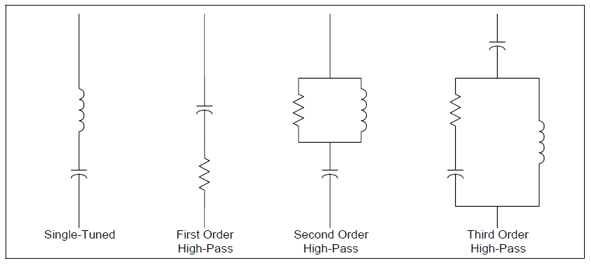
Passive filters are made of inductive, capacitive and resistive elements. They are relatively inexpensive compared with other means for eliminating harmonic distortion, but they have the disadvantage of potentially adverse interactions with the power system. They are employed either to shunt the harmonic currents off the line or to block their flow between parts of the system by tuning the elements to create a resonance at a selected harmonic frequency. Figure 1 shows several types of common filter arrangements.
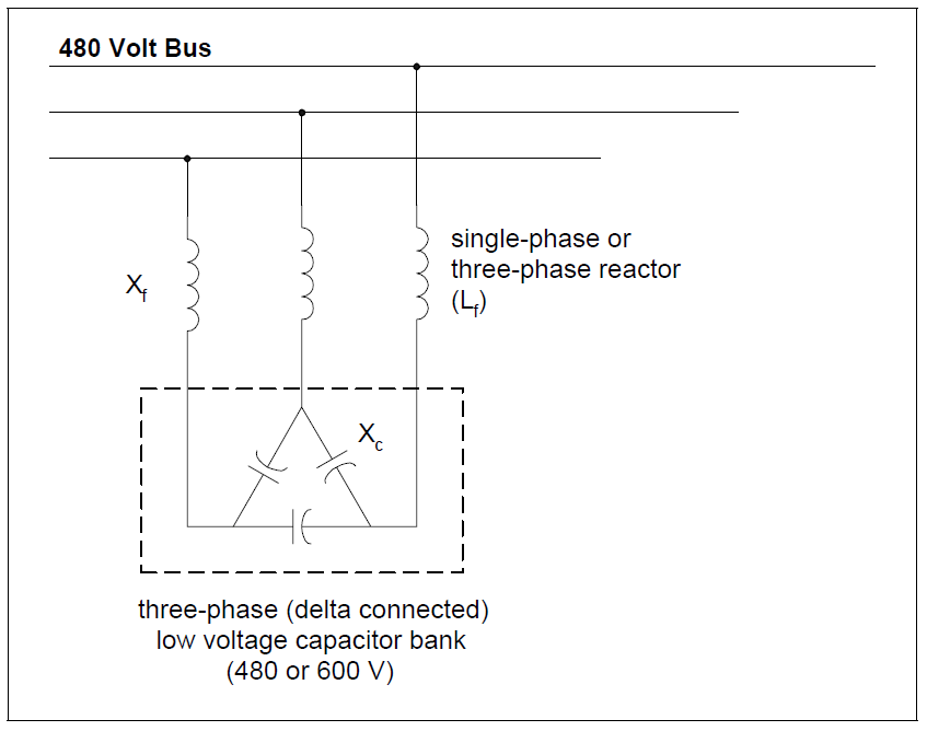
The most common type of passive filter is the single-tuned notch filter. This is the most economical type and is frequently sufficient for the application. An example of a common 480-volt filter arrangement is illustrated in Figure 2. The notch filter is series-tuned to present low impedance to a particular harmonic current. It is connected in shunt with the power system. Thus, harmonic currents are diverted from their normal flow path on the line into the filter. Notch filters can provide power factor correction in addition to harmonic suppression. Figure 2 shows a common delta-connected low-voltage capacitor bank converted into a filter by adding an inductance in series. In this case, the notch harmonic, hnotch, is determined using:
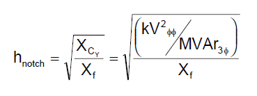
where:
XCY = equivalent wye capacitive reactance (Ω)
Xf = inductive reactance of filter reactor (Ω)
kVφφ = system rms phase-to-phase voltage (kV)
MVAr3φ = three-phase capacitor bank rating (MVAr)
One important side effect of adding a filter is that it creates a sharp parallel resonance point at a frequency below the notch frequency. This resonant frequency must be placed safely away from any significant harmonic. The harmonic number for the new parallel resonance can be approximated using:
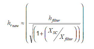
where:
hrnew = resulting (new) parallel resonant frequency (x fundamental)
XSC = system short circuit reactance (Ω)
Xfilter = reactance of series filter reactor (Ω)
This frequency should be checked when designing filters to make sure that the parallel resonance is not introduced at a lower order characteristic harmonic. For example, installing a 7th harmonic filter may retune the system to the 5th harmonic and actually increase the voltage distortion level. It is generally good practice to apply filters starting at the lowest characteristic harmonic to avoid this problem.
Filters are commonly tuned slightly lower than the harmonic to be filtered to provide a margin of safety in case there is some change in system parameters. If they were tuned exactly to the harmonic, changes in either capacitance or inductance with temperature or failure might shift the parallel resonance higher into the harmonic. This could present a situation worse than no filter because the resonance is generally very sharp. For this reason, filters are added to the system starting with the lowest problem harmonic. For example, installing a 7th harmonic filter usually requires that a 5th harmonic filter to have been installed first. The new parallel resonance with a 7th harmonic filter only would have been near the 5th harmonic. When the two are operated side-by-side, the 5th harmonic filter must be energized first and de-energized last
A delta-connected (capacitor) filter (Figure 2) does not admit zero-sequence currents because the capacitor is connected in delta. This makes it largely ineffective for filtering zero-sequence triplen harmonics. Other solutions must be employed when it becomes necessary to control zero-sequence 3rd harmonic currents. For capacitors connected in wye, you have the option of altering the path for the zero-sequence triplen harmonics simply by changing the neutral connection. Placing a reactor in the neutral of a capacitor is a common way to force the bank to filter only zero-sequence harmonics. This technique is often employed to eliminate telephone interference.
Passive filters should always be placed on a bus where the short circuit impedance (XSC) can be expected to remain relatively constant. While the notch frequency is determined by the filter tuning, and will remain fixed, the parallel resonance will move as the system short circuit impedance varies. For example, one common problem occurs in factories that have standby generation for emergencies. The parallel resonant frequency for running with standby generation alone is generally much lower than when interconnected with the utility. This may shift the parallel resonance down into a harmonic where successful operation is impossible. Filters often have to be removed for standby operation because of this. Filters must also be designed with the capacity of the bus in mind. The temptation is to size the current-carrying capability based solely on the load that is producing the harmonic. However, even a small amount of background voltage distortion on a very strong bus may impose severe duty on the filter.
HARMONIC FILTER DESIGN METHODOLOGY
The general method for applying passive harmonic filters is
1. Apply one single-tuned shunt filter first, and design it for the lowest generated frequency (e.g., 4.7th for a six-pulse drive).
2. Determine the voltage distortion level at the low voltage bus.
3. Vary the filter elements according to the specified tolerances and check its effectiveness.
4. Check the frequency response characteristic to verify that the newly created parallel resonance is not close to a harmonic frequency.
5. If required, investigate the need for several filters, such as 5th and 7th, or 3rd, 5th, and 7th.
Filters are generally tuned slightly below the harmonic frequency of concern. This method allows for tolerances in the filter components and prevents the filter from acting as a direct short circuit for the offending harmonic current. It also minimizes the possibility of dangerous harmonic resonance should the system parameters change and cause the tuning frequency to shift slightly higher.
Capacitor stress should be evaluated with respect to nameplate values. Contingency limits may be obtained from the manufacturer or from IEEE Std. 18. Filter reactor specifications should include both a fundamental and harmonic current value. In addition, the harmonic current should be determined assuming a reasonable value for background distortion from other sources.
LOW VOLTAGE HARMONIC FILTER DESIGN
The design of an industrial low voltage (480 volt bus) shunt passive harmonic filter, rated 500kVAr @ 600 volt (connection illustrated in Figure 2) is summarized in Table 1 and shown in detail below.
Reactive Compensation
The actual fundamental frequency compensation provided by a derated capacitor bank is determined using:

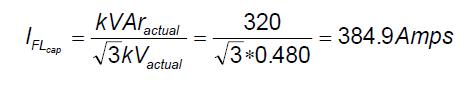
The fundamental frequency current for the capacitor bank is:
The equivalent single-phase impedance of the capacitor bank is:

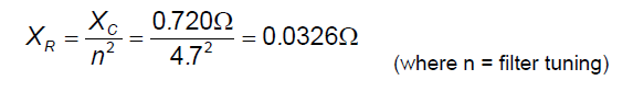
The filter reactor impedance is determined using:
Including the filter reactor increases the fundamental current to:

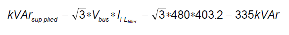
Due to the fact that the filter draws more fundamental current than the capacitor alone, the supplied compensation can be determined using:
Current and Voltage Determination
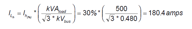
The next step involves evaluating the harmonic limits of the filter bank. The current from nonlinear load can be determined using:
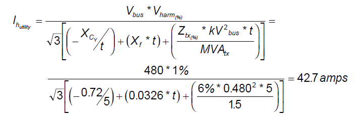
The current from utility (t = harmonic number for major component) can be determined using:
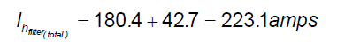
Assuming that the currents add, the harmonic filter load can be determined using:
The total rms current can be determined using:

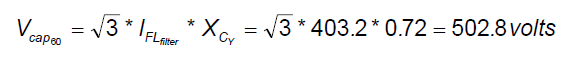
The next step involves evaluating the harmonic limits of the filter bank. The fundamental frequency capacitor voltage can be determined using:
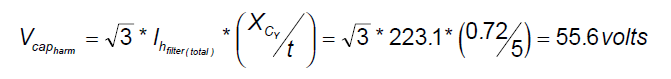
The harmonic voltage can be determined using:
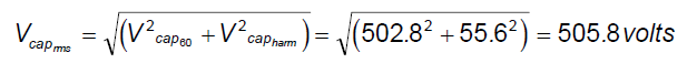
The total rms voltage can be determined using:
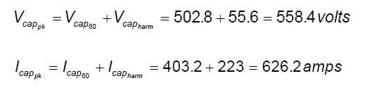
The peak voltage and current (assume in-phase addition) can be determined using:
Comparison with Harmonic Limits
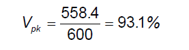
The final step is a check against voltage ratings. The peak voltage (120%) can be determined using:
The rms current (135%) can be determined using:

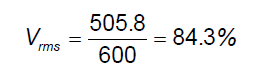
The rms voltage (110%) can be determined using:
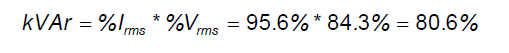
The total kVAr (135%) can be determined using:
Quality Factor
The quality factor of the filter is a measure of the sharpness of tuning and is defined as:
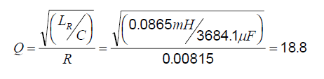
where:
R = series resistance of filter (Ω) / n = tuning / XR = filter impedance (Ω)
Typically, the value of R consists of only the resistance of the inductor. In this case, the Q of the filter is equal to (n*X/R ratio → 4.7*4=18.8). This usually results in a very large value of Q and a very sharp filtering action. The reactors used for filter applications are generally built with an air core, which provides linear characteristics with respect to frequency and current. A ±5% tolerance in the reactance is usually acceptable for industrial applications.
Resulting Parallel Frequency
The harmonic number for the new parallel resonance can be approximated using:
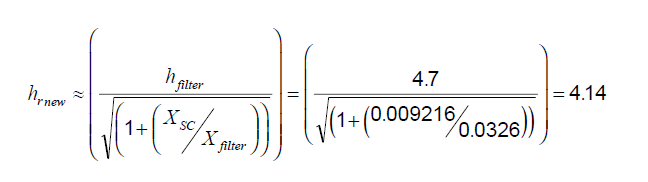
where:
hrnew = resulting (new) parallel resonant frequency (x fundamental)
XSC = system short circuit reactance (Ω)
Xfilter = reactance of series filter reactor (Ω)
Frequency Response
The frequency response characteristic illustrating the series resonance (low impedance) and resulting parallel resonance (high impedance) is shown in Figure 3.

SUMMARY
The industrial harmonic problem can be solved using a comprehensive approach including site surveys, harmonic measurements, and computer simulations. Simple calculations are used to determine the system resonant frequencies and then the preliminary model development is completed. Initial estimates of voltage distortion levels are made based on the level of harmonic current injection and the frequency response characteristic. A harmonic filter provides a low impedance path for harmonic currents, thereby minimizing harmonic voltage distortion problems.
REFERENCES
IEEE Recommended Practice for Electric Power Distribution for Industrial Plants (IEEE Red Book, Std 141-1986), October 1986, IEEE, ISBN: 0471856878
IEEE Recommended Practice for Industrial and Commercial Power Systems Analysis (IEEE Brown Book, Std 399-1990), December 1990, IEEE, ISBN: 1559370440
IEEE Recommended Practice for Protection and Coordination of Industrial and Commercial Power Systems, March 1988, IEEE, ISBN: 0471853925
