Published by Robert KOWALAK, Stanislaw CZAPP, Krzysztof DOBRZYNSKI, Jacek KLUCZNIK, Zbigniew LUBOSNY Gdansk, University of Technology, Faculty of Electrical and Control Engineering
Abstract. Voltage and current harmonics have a detrimental effect on the components of a power system. Current harmonics may result in the overload and damage to power transformers. Voltage harmonics may result in, for example, damage to capacitor banks used to compensate reactive power. Devices which contribute to both current and voltage distortion include traction rectifiers. This paper presents results of the computer investigation of the effect of these rectifiers on the power supply network. The results of the computer investigation have been compared with the result of experimental study.
Streszczenie. Wyższe harmoniczne napięcia i prądu oddziałują niekorzystnie na elementy sieci elektroenergetycznej. Z powodu wyższych harmonicznych prądu może dość do przeciążenia cieplnego i uszkodzenia transformatorów elektroenergetycznych. Wyższe harmoniczne napięcia mogą być przyczyną m.in. uszkodzenia baterii kondensatorów do kompensacji mocy biernej. Urządzeniami, które wywołują odkształcenia zarówno prądu, jak i napięcia są np. prostowniki trakcyjne. W artykule przedstawiono wyniki badań modelowych wpływu tych prostowników na elektroenergetyczną sieć zasilającą. Wyniki badań modelowych porównano z wynikami badań eksperymentalnych. (Harmoniczne powodowane pracą podstacji trakcyjnych – modelowanie i badania eksperymentalne).
Keywords: harmonics, modelling of power systems, power quality, power supply of electric traction.
Słowa kluczowe: harmoniczne, modelowanie systemu elektroenergetycznego, jakość energii, zasilanie trakcji elektrycznej.
Introduction
The voltage and current waveforms in a power grid sometimes significantly diverge from a sinusoid. Current distortions most often result from a non-linearity of loads. Distortions in voltage waveforms result from a distorted current flowing through the supply network, from switching processes and resonance phenomena. An increased content of higher harmonics in the voltage is also affected by the fact that “distorting” (non-linear) loads are supplied with already distorted voltage. This also leads to an additional (secondary) distortion in their current waveforms and, in consequence in the voltages in the supply network. An increased content of harmonics is also affected by the asymmetry of the supply voltage.
The distorted waveforms of voltages and currents can be described by means of the Fourier series:

where:
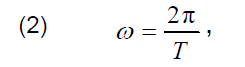
T – time period of the function f(t),

t0 – any value of the time t.
The greatest influence on power quality in a distribution network is displayed by high-power loads, such as arc furnaces or power electronics devices. The latter group includes, for example, traction rectifiers.
A significant level of harmonics in the supply voltage may lead, for example, to damage to the capacitor banks used to compensate reactive power. Damage to capacitor banks has been reported in several 110 kV/15 kV substations which supply medium voltage networks in Poland’s Pomorskie Region (Voivodship). These reports, and the need to determine the level of voltage distortion on the buses of power substations which supply disturbing loads (here: traction substations) and other consumers, have become the basis for supply network modelling and measurements in the extent described in this paper. The problem of insufficient power quality due to operation of traction substations is considered for various power systems [1, 2, 3, 4].
Based on studies available in the literature, it can be ascertained that there is a need to design computer models for traction substations to enable evaluating their impact on the power supply network, in particular on the distortion of current and voltage waveforms. As part of the research, computer models of four sample traction substations have been designed and their impact on the supply network has been analysed through simulation. DIgSILENT PowerFactory® software was used in the simulation tests. Next, voltages and currents were measured in those four sample facilities, and compared with the results of harmonic simulations. The comparison made it possible to assess the precision of the computer model.
Traction substation characteristics
There are more than 11,000 km of electrified railway lines DC 3 kV in Poland. The traction network is supplied by means of ca 450 traction substations equipped with 6-pulse and 12-pulse rectifiers. Most of these substations are supplied from medium voltage networks (usually 15 kV). Only the more recent facilities are supplied from 110 kV networks [5].
Traction substations are regarded as some of the larger loads by the power system operator. They are characterised by significant rated powers of rectifier sets. Moreover, they are considered to be so-called disturbing loads and their load current has significant dynamics of value change.
Reflected in the model, the structure of the electric traction supply systems is presented as a diagram in Fig. 1.

Among the harmonics introduced to the supply network by rectifiers, the highest values are achieved by so-called characteristic harmonics, with their order determined by the following dependence:

where: m – an integer, i.e. m = 1,2,3,…, p – ripple factor (number of pulses during one time period of alternating voltage).
Four typical traction substations operating in Poland were taken as the basis for designing the computer models of traction substations. All of the analyzed tractions substations are supplied from a 15 kV network through power cable lines. In three (designated I, II and III) out of four tested substations, PK-17/3,3 6-pulse rectifiers [6] are installed, supplied via TZE3-4402 rectifier transformers [7]. These substations are supplied from a 110 kV network via TORb-25000/110 transformers [8]. In one case (substation designated as IV), PD-12/3,3 rectifiers [9] are installed, supplied via TMOS3AA-4400/15PN rectifier transformers [10]. This medium voltage network is supplied via a TONRb-10000/115 transformer [11]. More precise information about the facilities cannot be provided as their administrators did not give their consent.
The model
The designed model (Fig. 2) takes into consideration the short-circuit power on the 110 kV side in the substation, a 110 kV/15 kV transformer installed in it and a 15 kV power line. The traction substation model takes into consideration a rectifier transformer, a rectifier and voltage smoothing devices (filters). In the analysed facilities, a traction unit constitutes an electrical load, but from the point of view of the supply network, the traction substation itself is considered to be such a load.

DIgSILENT PowerFactory® has built-in pre-existing model structures based on which one can create one’s own models of power grid components. In order to reflect “one’s own” facility, it is sufficient to input the relevant data to these models. This has been used when designing the components of the presented model, such as models of power system transformers and traction transformers, supply power lines and traction rectifiers. The pre-existing model structures were used because they were deemed appropriate for the assumed research – therefore, it was unnecessary to design our own models from scratch.
A traction vehicle is a traction substation’s load. Having reviewed the structures of traction vehicle drive units, it was decided that their precise modelling was not necessary. Based on the collected information, it was assumed that their influence on the level of voltage harmonics in the power supply network will be small. Therefore, the vehicle was modelled in the simplest way, as an impedance load.
Filters, a choke and a overvoltage protection system on the rectifier’s output have been included in the modelled traction substation. The facilities were modelled using RLC components. Because they influence the commutation processes in the rectifier, to omit them would affect the waveform of the substation’s supplying current.
A model built into the simulation software was used to model a 6-pulse traction rectifier. The model is described in detail in [12]. The diodes are shown in the model as ideal keys for which the forward and reverse resistances have been determined. The key is shunted by an RC overvoltage protection system. The parameters required for the model were determined based on [6]. The 12-pulse rectifier, in turn, was modelled using two 6-pulse rectifiers connected in series. The connection type and parameters corresponded to the data contained in [9].
Transformers were also modelled based on the models built into DIgSILENT. It is sufficient to input transformer specifications to such a model. A detailed description of a two-winding transformer is provided in [13], and of a three-winding transformer – in [14]. The data input method is illustrated in Fig 3.
The power line model used in the tests is also the model built into the simulation software. The power line is modelled as a four-terminal π network. The line parameters were determined on the basis of the data from the substation’s power supply systems. The power line model is described in detail in [15].
The power system is reflected as an ideal source of voltage and the impedance determined based on the known value of the short-circuit power.
Test results
At the first stage of the research, models of substation power supply systems were designed, based on the available information, and simulations were run. Then, measurements were performed, based on which the facility’s model was verified. The last step was to compare the harmonic content from the simulations and the measurements. This provided the basis for evaluating the simulation results and whether the computer model was correct.
A. Requirements for power quality
In a power grid with a voltage exceeding 1 kV, the accepted basic power quality parameters are frequency and voltage [16]. From the point of view of the impact of disturbing loads on the supply network, the content of higher harmonics in the voltage is the most important power quality parameter. The requirements for the quality of supply voltage in the analysed medium voltage network are described in the recommendations in [16, 17]. They are listed in Table 1.
Table 1. Permissible level of harmonics in voltage at the supply terminals (in percent of nominal voltage)

No specific requirements are determined for distortions in the load currents for the loads connected directly to the network. Such requirements are, however, determined for loads in an low voltage network.
B. Substation currents
A comparison of the current waveforms and their higher harmonics content obtained through measurements and simulations was used to verify the models designed for traction substation power supply systems. Current distortion assessment (from the point of view of power quality) was not performed due to the lack of formal requirements in this regard.
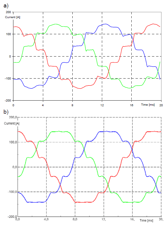
The following figures present selected current waveforms and the content of higher harmonics in the current in the analysed substations. The results correspond to each substation’s highest load recorded during the measurements.
Fig. 4 presents the current waveforms obtained for Substation I, and Fig. 5 – the content of the higher harmonics. Fig. 6 and 7 present the content of the higher harmonics in the load currents of Substations II and III. Fig. 8 presents the current waveforms, and Fig. 9 – the content of the higher harmonics obtained for Substation IV.


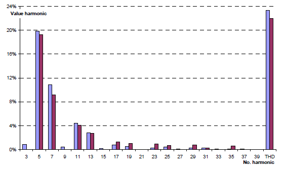

The greatest compliance between the computer model and the measurement data was obtained for Substations I and II. Greater discrepancies were found in Substations III and IV. There can be two reasons for this.
The first reason: the analysed power supply systems may not have been fully reflected. Unfortunately, not all the details of the modelled systems were obtained with success (the information on the 15 kV supply line and the equipment of the substation itself was incomplete). The incomplete data concerned the supply systems of Substations III and IV.
The second reason may be the supply voltage distortions in the real system. The analysed power substations supplied also other loads from the same 15 kV buses as the traction substations. Therefore, the voltage waveforms at the point of measurement was affected by other loads as well. The fact that a traction substation is supplied with a distorted voltage results in an additional (secondary) distortion of the current in the traction rectifier. As a result, the values of current harmonics characteristic for the rectifier may change; moreover, other harmonics that are not characteristic may appear.

An analysis of the presented results made it possible to ascertain that the designed models are satisfactorily precise in representing the load currents of the traction substations.
C. Supply voltage
The highest level of voltage distortion on the 15 kV buses of the power substation is expected when the value of the load current of a traction substation is the highest. The analyses took into consideration both the rated load of the traction rectifier and the permissible short-term overload (150% of rated load for up to 2 minutes).
It was assumed that the other loads in the 15 kV network, supplied from the same power substation’s buses, consumed the power equal to 10% of the 110 kV/15 kV transformer’s rated power. The results for the content of higher harmonics in the voltage on 15 kV power substation’s buses are presented in Fig. 10 to 13.
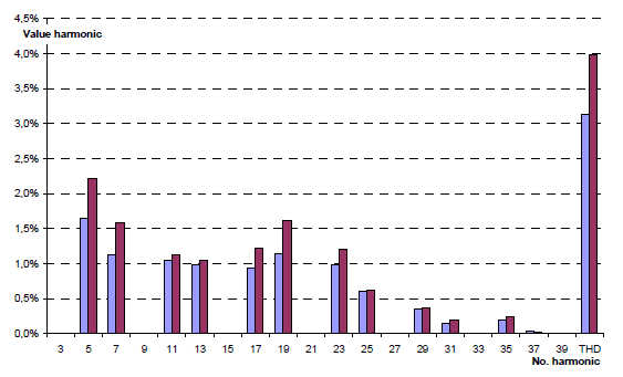


The simulations did not demonstrate that the substations operating in the analysed systems contributed to exceeding the permissible THD levels (see Table 1) in the voltage on the buses of the power substations which supplied them. They showed, however, that in Substation I, while at the permissible overload level, the 19th harmonic may increase above the permissible value. In the Substation IV supply system, in turn, the permissible level may also be exceeded for the 13th harmonic. As regards the other harmonics, the permissible levels were not found to be exceeded in any of the analysed systems.

The last element of the analysis was to compare the voltage distortions on 15 kV buses of the power substation obtained, during the modelling and measurements, for the same values of traction substations’ currents. The results were obtained at the highest recorded load current values of the traction substations, because the higher the value of the load current, the higher the level of voltage distortion that can be expected on the buses of the power substation. Examples of selected voltage waveforms obtained through measurement and simulation are presented in Fig. 14. Fig. 15, 16, 17 and 18, in turn, show the harmonic levels in the voltages on 15 kV buses of the power substation in the analysed traction substation power supply systems.
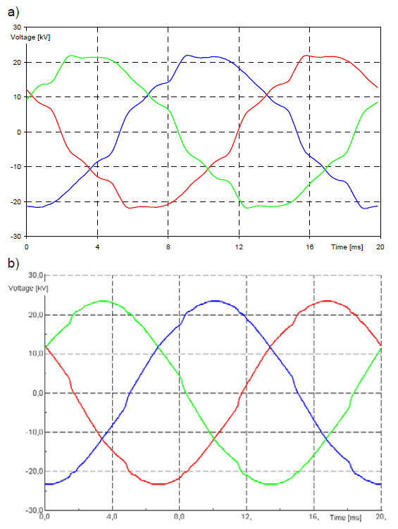
In the figures (Fig. 15 to 18), one can notice lower distortions in the waveforms obtained through simulation. This is fully justified. In the real system, many loads operated in the network, some of which introduced their own voltage distortions, whereas the simulations only analysed the operation of a traction rectifier. The presence of other loads in the 15 kV network was reflected by means of a single cumulative load as a set of RLC components, with its power and power factor specified on the basis of the information collected during the 110 kV/15 kV transformer’s load measurements.
In most cases, other harmonics were also measured on the buses of the power substation, next to the harmonics characteristic for the operation of traction rectifiers. Their presence is related to the operation of other loads in this network, as well as to the influence of the components of the network itself (for example transformers).

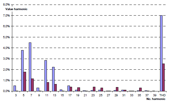

It is somewhat difficult to assess a traction substation’s influence on the overall level of harmonics in the power substation based on the performed simulations and measurements. It has been observed that in some cases the characteristic harmonics obtained in simulations reach higher values than those obtained in measurements. One possible explanation is that there is a greater ability to suppress higher frequencies in a real system than in a model. The second factor may be that in a network, currents are summed geometrically. As a result, certain harmonics can decrease in a real system compared to the impact of a single facility analysed in simulations.
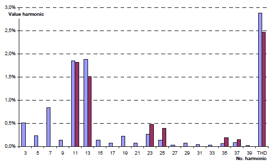
Nevertheless, the traction substations’ share in the overall distortion level, at least as regards characteristic harmonics, needs to be considered significant.
Neither the measurements nor their corresponding simulations demonstrated the presence in the voltage of the impermissible values of higher harmonics, either the odd ones, or the even ones which have not been presented in this paper.
Conclusion
When modelling the operation of a traction substation as a distorting load (harmonics), one can represent a real-life facility quite well. The main indicator of the degree to which a facility is represented in a model, in this case, is the waveform of the load current and the harmonics it contains. The more precise the system data, the greater the result compliance that has been achieved.
Unfortunately, this does not translate directly onto the possibility of assessing harmonics in the supply voltage on the 15 kV buses of a power substation, as it results from the interactions of all the loads connected to such a substation, along with the impact of the whole network. An additional difficulty comes in the fact that the harmonics contained in load currents are not summed algebraically. In extreme cases, the result may be a significant increase in the value of some harmonic in the voltage, or conversely, a marked decrease compared to what would follow from an analysis of a single load.
The simulation results may provide information about how much a given load (here: a traction substation) can influence the power quality at the point of connection. If a significant impact is discovered, one can try to persuade the facility’s owner to make them introduce, for example, specific higher harmonics filters to eliminate them from the load current. Simulation results can be very useful when assessing the influence of a traction substation’s modernization on power quality. They also allow one to assess the impact on the power supply network of a new traction substation that is only at the planning stage.
REFERENCES
[1] Yu-quan L., Guo-pei W., Huang-sheng H., Li W., Research for the effects of high-speed electrified railway traction load on power quality, 4th Int. Conf. on Electric Utility Deregulation and Restructuring and Power Technologies (DRPT), 2011
[2] Župan A., Tomasov i ć Tekl i ć A., Fi l i pov i ć-Grč i ć B. , Modeling of 25 kV electric railway system for power quality studies, EuroCon, 1-4 July 2013, Zagreb, Croatia
[3] Djeghader Y., Zellouma L., Labar H., Toufout i R ., Chel l i Z. , Study and filtering of harmonics in a DC electrified railway system, 7th International Conference on Modelling, Identification and Control (ICMIC), Sousse, Tunisia – December 18-20, 2015
[4] Pawelek R. , Analysis of current and voltage higher harmonics measurements performed in selected traction substation, Przeglad Elektrotechniczny, 90 (2014), nr 7, 234- 238
[5] Report RAILWAY BUSINESS FORUM, Electrical power railway, Warsaw, February 2011
[6] Technical documentation of PK-17/3,3 rectifier, Elta, Lodz 1971
[7] Catalogue SWW 1113: Transformers and special reactors, Edition III, WEMA, Warsaw 1975
[8] Catalogue Power transformers, EV Zychlinskie Transformatory, 2006
[9] Technical documentation of PD-12/3,3 rectifier, Elta, Lodz 1988
[10] Technical documentation of TMOOS3AA-4400/15N transformer, Elta, Lodz 1987
[11] Catalogue SWW 1113-2: Oil-filled power transformers and autotransformers, WEMA, Warsaw 1975
[12] DIgSILENT Technical Documentation, 6-Pulse Bridge, 2006
[13] DIgSILENT Technical Documentation, Two-Winding Transformer (3-Phase), 2007
[14] DIgSILENT Technical Documentation, Three-Winding Transformer, 2007
[15] DIgSILENT Technical Documentation, Overhead Line Models, 2007
[16] Operation and Maintenance Instruction of Distribution Network, ENERGA-OPERATOR joint-stock company, 2016
[17] Standard EN 50160: Voltage Characteristics of Public Distribution Systems, 2010
Authors: dr inż. Robert Kowalak, E-mail: robert.kowalak@pg.gda.pl; dr hab. inż. Stanisław Czapp, E-mail: stanislaw.czapp@pg.gda.pl; dr inż. Krzysztof Dobrzyński, E-mail: krzysztof.dobrzynski@pg.gda.pl; dr inż. Jacek Klucznik, E-mail: jacek.klucznik@pg.gda.pl; prof. dr hab. inż. Zbigniew Lubośny, E-mail: zbigniew.lubosny@pg.gda.pl; Gdansk University of Technology, Faculty of Electrical and Control Engineering, ul. Gabriela Narutowicza 11/12, 80-233 Gdańsk, Poland.
Source & Publisher Item Identifier: PRZEGLĄD ELEKTROTECHNICZNY, ISSN 0033-2097, R. 93 NR 6/2017. doi:10.15199/48.2017.06.04
