Published by Wojciech MATELSKI1, Electrotechnical Institute, Warsaw
Abstract. The article describes a practical implementation of the induction motor (IM) drive system powered from photovoltaic (PV) panels. The system incorporates an energy storage device, in form of a supercapacitor bank, and enables an AC grid connection. Two system concepts are considered, thus a discussion about the favorable solution is given. A model installation was developed, and the chosen system components are described. Laboratory tests have been conducted and the results are presented.
Streszczenie. W artykule opisano praktyczną implementację napędu z silnikiem indukcyjnym (IM) zasilanym z paneli fotowoltaicznych (PV). System zawiera zasobnik energii, w formie baterii superkondensatorów, oraz posiada możliwość podłączenia do sieci AC. W pracy rozpatrzono dwie koncepcje realizacji systemu oraz przedstawiono dyskusję dotyczącą korzystniejszego rozwiązania. Opracowano instalację modelową oraz opisano wybrane komponenty systemu. Praca zawiera wyniki wstępnych badań laboratoryjnych (Układ zasilania napędu indukcyjnego z baterii fotowoltaicznej z magazynem energii – model eksperymentalny).
Keywords: induction motors; photovoltaic systems; supercapacitors; variable speed drives.
Słowa kluczowe: silniki indukcyjne, systemy fotowoltaiczne, superkondensatory, napędy z regulowaną prędkością.
Introduction
Solar energy is considered as the most environment friendly renewable energy source. Comparing to other renewables, converting solar radiation into electricity pollutes the environment to the smallest extent. As technology advances, the efficiency of solar panel systems is increasing, and in recent years, the price per kilowatt peak power is dropping with a steady rate. Despite this fact, solar panel systems are still costly, and large solar power plants are economically justified in areas of appropriate insolation. Even though, there are several applications, where due to other considerations, solar power appears to be a reasonable solution.
Very often water pumps, used in agriculture for field irrigation, are installed in remote or rural areas, where the industrial power grid is not available. In literature several concepts of solar energy-based water pumping are described [1 – 8]. Water flow is forced by the work of pumps driven by DC [2] or AC motors [1, 5 – 9]. Thanks to their robustness, simple structure and low cost, induction motors are a common solution [1, 5 – 7].
Power generation from solar panels strongly depends on the current weather conditions. In a straight forward approach, when the solar radiation is sufficient, the pumping system can operate, providing fresh water on the field. The drive works intermittently. To make the system more cost effective, electrical energy storage devices are avoided [1, 5 – 8]. In this way, the system level of complexity is reduced. In reference [1] a small power, mobile pump system for water filtration purposes is presented. In exchange for the lack of electrical energy storage, water tanks can be applied, so that water is gathered for later use. Even though, the power rating of the solar panel has to be large enough, to enable motor start and satisfy the load demand. In such systems motor stall is possible.
On the other hand, incorporation of a battery pack [2 – 4] makes the installation independent from solar radiation and expands the functionality of the solar water pump system. For example, remote control through GSM network can be implemented [2 – 4]. Reference [3] presents an automated irrigation system for optimization of water use for agricultural crops. Field tests were carried out and water savings up to 90% were achieved in comparison with traditional irrigation practices on the test agricultural zone. What is more, thanks to energy storage devices, the power rating of the solar panels can be lowered, and the risk of motor stall is reduced. Even under low insolation conditions, the energy can be cumulated in order to enable short-time higher power values, which is perfect for intermittent mode of motor operation.
Solar panels operate with the best efficiency at a specific load current and output voltage. This is achieved through implementation of a maximum power point tracking algorithm MPPT. In batteryless systems the load demand is regulated. Considering solar pump drives, the speed of the motor can be adapted according to insolation sensor readings [6] or various perturb and observe algorithms [1, 5, 7]. The command speed depends on load conditions. Thus the control possibilities of the drive are reduced. A battery pack enables independent speed control (when the stored energy is sufficient) of the motor. MPPT is usually provided by an additional DC/DC battery charging converter.
Reference [9] describes a batteryless AC drive system, powered from solar panels, supported from the electrical grid. The power rating of the photovoltaic battery can be lower, and thus the system costs can be reduced. This solution is completely independent from current weather conditions.
Solar panel generation units are also a reasonable solution in elevator applications. The presence of an auxiliary source of power, supporting the AC grid, improves the reliability of the drive system. Together with an energy storage device, the system can provide some additional safety features, which is crucial in elevator applications. For example, in case of power failure, the stored energy is used to supply the traction motor in order to move the cabin to the nearest floor, open the door and enable the evacuation of the passengers. In [10 – 12] elevator systems, powered from a DC microgrid with solar panels and energy storage units and an AC grid connection, are presented. The main focus of the research was the elaboration of energy management algorithms to optimize the operation of the elevator drive system, and reduce the power consumption from the AC grid.
This article describes a practical implementation of the induction motor IM drive system supplied from photovoltaic PV panels. The system incorporates an energy storage device, in form of a supercapacitor bank, and enables an optional AC grid connection. Two system concepts are considered, thus a discussion about the favorable solution is given. A model installation was developed, and the chosen system components are described. Laboratory tests have been conducted and the results in form of selected waveforms are presented.
Solar powered drive with energy storage
The presented in this article drive system consists of an induction motor, powered from a solar panel array. The general concept of the system, in form of a block diagram, is depicted in Figure 1. Considering the moderate irradiation conditions in Poland, the solution incorporating an energy storage device has been adopted. The system can be used in applications characterized by intermittent operation, like water pumps for field irrigation or elevator systems.

For energy storage purposes supercapacitors SC were chosen. Even if their energy density is not comparable to that of conventional electrochemical accumulators, like the commonly used lead-acid batteries, their high power density, large number of charge and discharge cycles (approximately 1 million), shorter charging times and the possible amount of stored energy, makes them compatible with many industrial applications [13], like for example elevator systems [9 – 13]. What is more, lead-acid battery banks are heavy and expensive and their lifetime is estimated to be one fifth of the lifetime of a solar panel [5].
As can be seen from Figure 1, the system does include an optional industrial low voltage three phase grid connection. In this way, the system becomes a more reliable power source, so the operation of the load can be ensured for example in emergency situations. In cases of poor weather conditions, energy can be drawn from the grid in order, if necessary, to fed the load, or it can be stored in the SC, when the prices are low, for example at night.
The power flow is controlled by the means of power electronic converters, and in the block scheme from Figure 1, they are contained in the block denoted as PES. This structure will be discussed in detail in the next section.
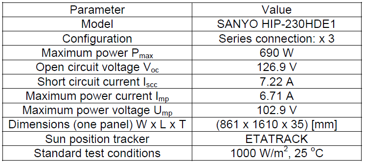
For the purpose of this research, an existing 690 W solar panel system, installed at the parking lot of the Electrotechnical Institute, was used. The solar panels are presented in Figure 2, and their parameters are listed in Table 1.
Table 1. Photovoltaic panels system parameters
Having regard to the intermittent operation of the drive system, thanks to the presence of the supercapacitor as an integral part of the installation, the power rating of the motor can be larger than the nominal power generated by the solar panels. In situations of cloudy weather, a small power level can be achieved, but with the energy stored over a longer period of time, the supercapacitor can deliver power sufficient to start even a larger motor.
System structure considerations
The type and configuration of the power electronic converters in the solar drive system determine its performance and capabilities. For further research two system structures were analyzed. The configurations are presented in Figure 3 and Figure 4, and were denoted as CONFIG 1 and CONFIG 2 respectively.
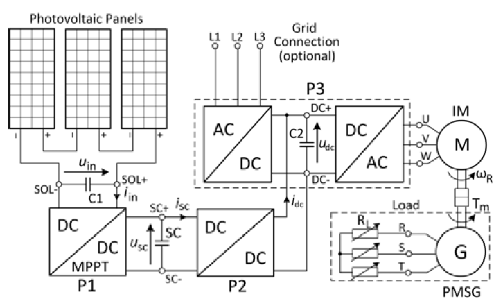
The IM is powered through a variable frequency converter, in Figure 3 and Figure 4 denoted as P3, and controlled by its inverter DC/AC part. The electrical energy from the solar panels can be supplied via the DC link terminals DC+, DC- of converter P3.

The main aspect distinguishing CONFIG 1 from CONFIG 2 is the location of the SC in the structure, which in consequence strongly affects the function and requirements for converter P2 in the system. This feature also has influence on the principle of operation of converter P1.

The adopted motor is a 400 V (phase to phase RMS) machine. To ensure proper operation, the DC link voltage udc of converter P3 needs to be sustained on a high enough level. In both configurations an optional connection to the industrial electricity grid is assumed. The drive can be powered solely by the solar panels when udc is kept higher than the rectified three phase grid voltage provided by the AC/DC part (three phase bridge diode rectifier) of converter P3. In this way, the energy consumption from the grid is disabled. This principle of operation, together with the relatively low voltage output level generated by the solar panels (cf. Tab. 2), enforces the boost character of converters P1 and P2 regarding CONFIG 1, and converter P2 as for CONFIG 2.
The level of insolation, at which photovoltaic cells are exposed, determines the power they produce. The U-I characteristics of solar panels are non-linear. The efficiency of the conversion of sunlight into electricity reaches its best performance at a specific output voltage. Several techniques are described and applied in order to keep this voltage on a desired level. In this way, maximum power point tracking MPPT is achieved. Considering CONFIG 1, in order to perform MPPT, converter P1 has to cooperate either with converter P2, or with the inverter part of P3, or together with both converters. In the first case, the drive has to be stopped, and the energy is stored in the SC. In situations when the IM needs to operate, but the SC is fully charged, MPPT can be realized by adapting the output voltage frequency command of converter P3, so that the power consumption of the IM is altered. At last, when uSC doesn’t exceed its maximum value, the surplus energy is used to charge the SC, thus enabling independent control of the drive. As for CONFIG 2, if the SC is not fully charged, MPPT can be realized solely by P1.
Comparing CONFIG 1 and CONFIG 2 it can be seen, that for the same modes of operation, the power flows through a different number of conversion stages, i.e. converters. Each conversion stage is associated with power losses. The main modes of operation, together with the number of conversion stages, are listed in Table 2.
From Table 2, in modes 2, 3 and 4 the number of converters taking part in the operation of the system for CONFIG 1 and CONFIG 2 is equal.
Considering mode 5, when powering the drive only by the solar panels (the SC is fully charged or discharged) CONFIG 1 has the advantage, because the operation is associated with a smaller number of converters, than for CONFIG 2. CONFIG 1 is more suitable for systems where the nominal power of the solar panels is equal to the power demand of the drive.
Mode 1 has to be analyzed together with mode 3. In this case CONFIG 2 is more efficient. This solution is applicable for systems characterized by intermittent operation, where the motor power exceeds the power generation of the solar panels, and the lack is covered by the energy stored in the supercapacitor.
Table 2. Main modes of system operation and the corresponding power conversion levels

Experimental setup
In order to perform laboratory tests, the system presented in Figure 1 has been built. In the establishment, components from former projects have been utilized and are listed in Table 3.
The power of the adopted induction motor IM (cf. Tab. 3) equals 3 kW and is greater than the 690 W of the solar panels (cf. Tab. 1). Therefore CONFIG 2, presented in Figure 4, has been chosen for further laboratory tests.
Table 3. Laboratory model system description

Converter P1 is used to charge the SC and ensure MPPT of solar panels. The scheme of converter P1 is presented in Figure 5a. Converter P2 serves to boost the voltage of the SC to the requirements of the DC link of converter P3, which equals approximately 600 V. The converter scheme is presented in Figure 5b. The structure of P2 enables bidirectional power flow. In this way, when the drive operates in generator mode, energy recuperation is possible. Converters P1 and P2 have been realized in interleaved technology. This solution consists of a parallel connection of identical converters (legs), which can give a number of advantages. The effective output voltage frequency is higher. As a result the load current pulsations are decreased. What is more, converter reliability is improved, and the power ratings of necessary components can be reduced [14, 15]. P3 is a commercial LG LS 5,5 kW variable frequency drive and its structure is presented in Figure 5c. The DC/AC part is a two-level three phase bridge inverter operated with the volt/hertz control principle. The AC/DC part is a three phase diode bridge rectifier. The terminals U, V, W are used to connect the IM. The motor is directly coupled with a 3 kVA permanent magnet synchronous generator PMSG. The drive test bench includes an incremental encoder for speed measurements and a torque sensor and is described in [16]. The PMSG is connected to a variable resistance load RL. The built solar drive laboratory model installation is presented in Figure 6 and Figure 7.


The converters P1 and P2 are run by a control board, incorporating a DSP TI TMS320F28335 microcontroller together with a FPGA ALTERA CYCLONE III unit. The P3 converter is controlled by DSP TI TMS320F2812 unit.

Laboratory results
The proposed system is still under development. Some first laboratory tests have been conducted, including a part of the model installation. The results in form of selected waveforms are depicted in Figure 8 and Figure 9.
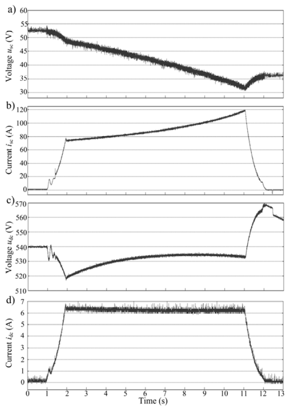
During the test, the grid was disconnected. The solar panels and converter P1 also did not take part at this stage of research. The SC has been precharged before the experiment started (cf. Fig. 8a). The waveforms have been registered by RejDiag application, developed in the Electrotechnical Institute. This program is operated from a PC and it enables the communications with the DSP control boards. The measuring points were as presented in Figure 4. The PMSG was loaded with a constant resistance RL of 67 Ω per phase.
In the experiment the command output voltage frequency signal fe of converter P3 was changed, to adjust the rotational speed nR of the IM (cf. Fig. 9b), so that it should resemble an elevator moving from one floor to another. After about 1s fe was increased from 0 Hz to 30 Hz, during a 1s interval, so the motor started and accelerated with a steady rate. The DC link voltage udc, presented in Figure 8c, decreased and when it dropped under the trigger value of 530 V, converter P2 turned on, in order to discharge the SC and maintain udc on the reference value. After fe reached 30 Hz (t = 2s) the IM started constant speed operation. The developed torque Tm also remains constant (cf. Fig. 9c). In this way, the mechanical power demand Pm (cf. Fig. 9d), calculated as:

also remains constant. Converter P2 delivers power Pdc, presented in Figure 9a, calculated as:

where: idc – output current of converter P2 [A],
to the DC link of converter P3. The SC is being discharged, so that the supercapacitor voltage usc, presented in Figure 8a, decreases. In order to deliver constant power Psc, presented in Figure 9a, calculated as:
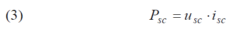
the input current for converter P2 isc drawn from the SC has to increase, which can be seen in Figure 8b. At t = 11s, fe starts decreasing to reach 0 Hz, after another 1s. The motor decelerates operating in generator mode, thus udc increases exceeding its reference value. Therefore converter P2 regulates the current drawn from the SC to 0 A.
From the beginning of the test, the supercapacitor voltage was deliberately set below the half of its nominal value (cf. Tab. 3). Converter P2 needs to boost this voltage to the level of the DC link voltage udc, so the boost factor varies from about 10 at the start of the test, to almost 17 at the end of constant speed operation. Converter P2 has difficulties in maintaining udc on the reference value 540 V. But despite those harsh conditions, the motor is still operational, and the efficiency of converter P2 is satisfactory: at t = 2s it equals 92%, and at t = 11s drops to 88% (cf. Fig. 9a). The voltage of the SC decreases, so in order to deliver constant power to the drive, the current drawn from the SC is increasing, thus the power losses in the system also increase. This can be observed in Figure 9a, where Pdc is on a steady level (constant speed region), while Psc is increasing. The supercapacitor has to cover for rising power losses due to the increasing discharge current.

Conclusion
The solar powered induction motor drive system, with energy storage in form of a supercapacitor and possible grid connection, has been presented. The system is meant for application with field irrigation water pumps and especially elevator installations.
In the article two system structures have been described and compared. The relationship between the power of the solar panels and the power of the drive determines the more favorable solution. A model for laboratory tests, including a 690 W solar installation and a 3 kW induction motor drive system has been developed. Some first laboratory tests including a part of the model installation were conducted. The supercapacitor supplies the drive with sufficient power, even in states of high depth of discharge. The applied converter is able to boost the voltage according to the requirements of the DC link of the inverter. Although due to the high current drawn from the SC, the efficiency of the boost converter gets affected. Therefore it is wise not to let the SC get discharged under the half of its nominal voltage. Besides, at that point there is only 25% energy left.
The system is still under research. Further tests, including all components of the model, such as power and efficiency measurements on each stage of power conversion, need to be carried out.
Projekt finansowany ze środków NCBiR w ramach programu INNOMOTO: “Wielofunkcyjny system ‘inteligentnych’ sprzężeń multilateralnych (WSISM) pojazdów elektrycznych z siecią dystrybucyjną, zasobnikami i odnawialnymi źródłami energii”. Aplikacja no.: POIR.01.02.00-00-0277/16.
REFERENCES
[1] Chualin J., Wei J., Design of a digital controlled solar water pump drive system for a nano-filtration system, Ninth International IEEE Conference on Power Electronics and Drive Systems (PEDS), (2011), 982-986
[2] Ganesh K., Girisha S., Embedded controller in farmers pump by solar energy (automation of solarised water pump), IEEE International Conference on Recent Advancements in Electrical, Electronics and Control Engineering (2011), 226-229
[3] Gutierrez J., Villa-Medina J.F., Nieto-Garibay A. Porta-Gandara M.A., Automated irrigation system using a wireless sensor network and GPRS module, IEEE Transactions on Instrumentation and Measurement, Vol. 63 (2014), No. 1, 166-176
[4] Alex G., Janakiranimanthi M., Solar based plant irrigation system, International Conference on Advances in Electrical, Electronics, Information, Communication and Bio-Informatics (AEEICB16), IEEE, (2016)
[5] Vitorino M.A., de Rossiter Correa M.B, Jacobina C.B., Lima A.M.N, An Effective Induction Motor Control for Photovoltaic Pumping, IEEE Transactions on Industrial Electronics, Vol. 58 (2011), No. 4, 1162-1170
[6] Kolano K., Kolano J., Praktyczna realizacja układów napędowych z trójfazowym silnikiem indukcyjnym zasilanym z baterii ogniw fotowoltaicznych, Zeszyty Problemowe – Maszyny Elektryczne, Nr 77 (2007), 5-10
[7] Kusio M., Maksymalizacja mocy układu napędowego klimatyzacji zasilanego z generator PV, Prace Instytutu Elektrotechniki, Zeszyt 236 (2008), 76-86
[8] Singh B., Mishra A.K., Kumar R., Solar powered water pumping system employing switched reluctance motor drive, IEEE Transactions on Industry Applications, Vol. 52 (2016), No.5, 3949-3957
[9] Kolano K., Układ napędowy zasilany z baterii ogniw fotowoltaicznych współpracujący z siecią elektroenergetyczną, Napędy i Sterowanie, Nr 2 (2011), 80-84
[10] Lin Y., Liu Y., Simulation and experiment research on a new elevator system with solar energy and super capacitor, Journal of Software Engineering, 9 (3), (2015), 534-547
[11] Pham T.H., Prodan I., Genon-Catalot D., Lefevre L., Efficient energy management for an elevator system under a constrained optimization framework, 19th International Conference on System Theory, Control and Computing (ICSTCC), October 14-16, Cheile Gradistei, Romania, IEEE (2015), 613-618
[12] Nikolić T.R., Nikolić G.S., Petrović B.D., Sojcev M.K., Elevator system with dual power supply, Facta Universitatis, Automatic Control and Robotics, Vol. 14 (2015), No. 3, 159-172
[13] Rufer A., Barrade P., A supercapacitor-based energy storage system for elevators with soft commutated interface, IEEE Transactions on Industry Applications, Vol. 38 (2002), No. 5, 1151-1159
[14] Matelski W., Low power DC/DC converter from 3 kV to 300 V: simulation analysis, IAPGOŚ, Vol. 6 (2016), No. 2, 44-47
[15] Matelski W., Wolski L., Abramik S., Dwukierunkowa przetwornica DC/DC z wykorzystaniem elementów SiC, IAPGOŚ, Vol. 6 (2016), No. 3, 64-69
[16] Matelski W., Łowiec E., Abramik S., Symulator małej turbiny wiatrowej, Prace Instytutu Elektrotechniki, Zeszyt 273 (2016), 63-77
Authors: mgr inż. Wojciech Matelski, Instytut Elektrotechniki, Bałtycka Pracownia Technologii Energoelektronicznych (BaPTE), ul. Chechosłowacka 3, Park Konstruktorów, 81-336 Gdynia, E-mail: wojciech.matelski@iel.pl.
Source & Publisher Item Identifier: PRZEGLĄD ELEKTROTECHNICZNY, ISSN 0033-2097, R. 94 NR 2/2018. doi:10.15199/48.2018.02.42
