Published by Electrical Installation Wiki, Chapter J. Overvoltage protection – Surge protection technical supplements
Lightning protection standards
The IEC 62305 standard parts 1 to 4 (NF EN 62305 parts 1 to 4) reorganizes and updates the standard publications IEC 61024 (series), IEC 61312 (series) and IEC 61663 (series) on lightning protection systems.
Part 1 – General principles
This part presents general information on lightning and its characteristics and general data, and introduces the other documents.
Part 2 – Risk management
This part presents the analysis making it possible to calculate the risk for a structure and to determine the various protection scenarios in order to permit technical and economic optimization.
Part 3 – Physical damage to structures and life hazard
This part describes protection from direct lightning strokes, including the lightning protection system, down-conductor, earth lead, equipotentiality and hence SPD with equipotential bonding (Type 1 SPD).
Part 4 – Electrical and electronic systems within structures
This part describes protection from the induced effects of lightning, including the protection system by SPD (Types 2 and 3), cable shielding, rules for installation of SPD, etc.
This series of standards is supplemented by:
- the IEC 61643 series of standards for the definition of surge protection products (see The components of a SPD );
- the IEC 60364-4 and -5 series of standards for application of the products in LV electrical installations (see End-of-life indication of a SPD)
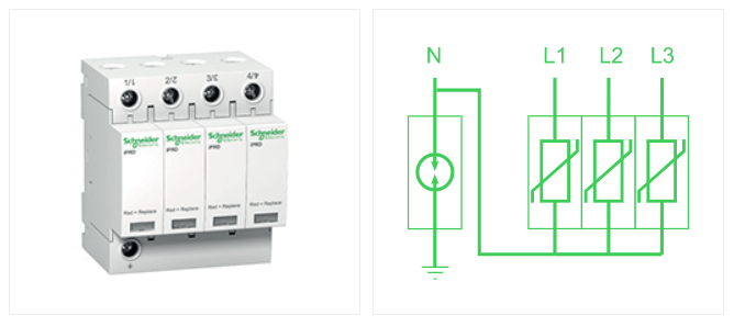
The components of a SPD
The SPD chiefly consists of (see Fig. J50):
1) one or more nonlinear components: the live part (varistor, gas discharge tube, etc.);
2) a thermal protective device (internal disconnector) which protects it from thermal runaway at end of life (SPD with varistor);
3) an indicator which indicates end of life of the SPD; Some SPDs allow remote reporting of this indication;
4) an external SCPD which provides protection against short circuits (this device can be integrated into the SPD)

Technology of the live part
Several technologies are available to implement the live part. They each have advantages and disadvantages:
• Zener diodes;
• The gas discharge tube (controlled or not controlled);
• The varistor (zinc oxide varistor).
The table below shows the characteristics and the arrangements of 3 commonly used technologies.
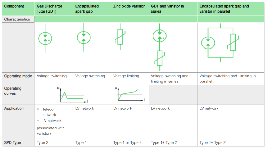
Note: Two technologies can be installed in the same SPD (see Fig. J52)
End-of-life indication of a SPD
End-of-life indicators are associated with the internal disconnector and the external SCPD of the SPD to inform the user that the equipment is no longer protected against overvoltages of atmospheric origin.
Local indication
This function is generally required by the installation codes. The end-of-life indication is given by an indicator (luminous or mechanical) to the internal disconnector and/or the external SCPD.
When the external SCPD is implemented by a fuse device, it is necessary to provide for a fuse with a striker and a base equipped with a tripping system to ensure this function.
Integrated disconnecting circuit breaker
The mechanical indicator and the position of the control handle allow natural end-of-life indication.
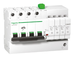
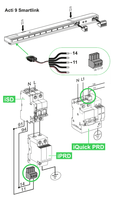
Local indication and remote reporting
iQuick PRD SPD of the Schneider Electric brand is of the “ready to wire” type with an integrated disconnecting circuit breaker.
Local indication
iQuick PRD SPD (see Fig. J53) is fitted with local mechanical status indicators:
• the (red) mechanical indicator and the position of the disconnecting circuit breaker handle indicate shutdown of the SPD;
• the (red) mechanical indicator on each cartridge indicates cartridge end of life..
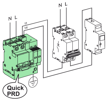
Remote reporting
(see Fig. J54)
iQuick PRD SPD is fitted with an indication contact which allows remote reporting of:
• cartridge end of life;
• a missing cartridge, and when it has been put back in place;
• a fault on the network (short circuit, disconnection of neutral, phase/neutral reversal);
• local manual switching.
As a result, remote monitoring of the operating condition of the installed SPDs makes it possible to ensure that these protective devices in standby state are always ready to operate.
Maintenance at end of life
When the end-of-life indicator indicates shutdown, the SPD (or the cartridge in question) must be replaced.
In the case of the iQuick PRD SPD, maintenance is facilitated:
• The cartridge at end of life (to be replaced) is easily identifiable by the Maintenance Department.
• The cartridge at end of life can be replaced in complete safety, because a safety device prohibits closing of the disconnecting circuit breaker if a cartridge is missing.
Detailed characteristics of the external SCPD
Current wave withstand
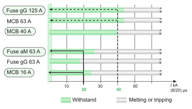
The current wave withstand tests on external SCPDs show as follows:
• For a given rating and technology (NH or cylindrical fuse), the current wave withstand capability is better with an aM type fuse (motor protection) than with a gG type fuse (general use).
• For a given rating, the current wave withstand capability is better with a circuit breaker than with a fuse device.
Figure J56 below shows the results of the voltage wave withstand tests:
• to protect a SPD defined for Imax = 20 kA, the external SCPD to be chosen is either a MCB 16 A or a Fuse aM 63 A,
Note: in this case, a Fuse gG 63 A is not suitable.
• to protect a SPD defined for Imax = 40 kA, the external SCPD to be chosen is either a MCB 40 A or a Fuse aM 125 A,
Installed Up voltage protection level
In general:
• The voltage drop across the terminals of a circuit breaker is higher than that across the terminals of a fuse device. This is because the impedance of the circuit-breaker components (thermal and magnetic tripping devices) is higher than that of a fuse.
However:
• The difference between the voltage drops remains slight for current waves not exceeding 10 kA (95% of cases);
• The installed Up voltage protection level also takes into account the cabling impedance. This can be high in the case of a fuse technology (protection device remote from the SPD) and low in the case of a circuit-breaker technology (circuit breaker close to, and even integrated into the SPD).
Note: The installed Up voltage protection level is the sum of the voltage drops:
• in the SPD;
• in the external SCPD;
• in the equipment cabling
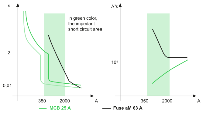
Protection from impedant short circuits
An impedant short circuit dissipates a lot of energy and should be eliminated very quickly to prevent damage to the installation and to the SPD.
Figure J57 compares the response time and the energy limitation of a protection system by a 63 A aM fuse and a 25 A circuit breaker.
These two protection systems have the same 8/20 µs current wave withstand capability (27 kA and 30 kA respectively).
Propagation of a lightning wave
Electrical networks are low-frequency and, as a result, propagation of the voltage wave is instantaneous relative to the frequency of the phenomenon: at any point of a conductor, the instantaneous voltage is the same.
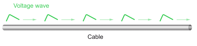
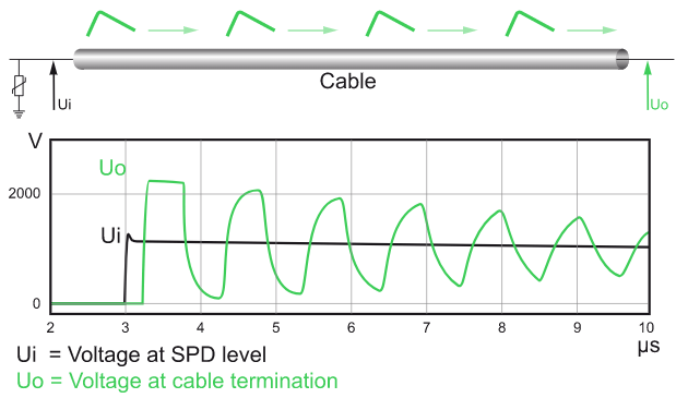
The lightning wave is a high-frequency phenomenon (several hundred kHz to a MHz):
• The lightning wave is propagated along a conductor at a certain speed relative to the frequency of the phenomenon. As a result, at any given time, the voltage does not have the same value at all points on the medium (see Fig. J58).
• A change of medium creates a phenomenon of propagation and/or reflection of the wave depending on:
• the difference of impedance between the two media;
• the frequency of the progressive wave (steepness of the rise time in the case of a pulse);
• the length of the medium.
In the case of total reflection in particular, the voltage value may double.
Example: case of protection by a SPD
Modelling of the phenomenon applied to a lightning wave and tests in laboratory showed that a load powered by 30 m of cable protected upstream by a SPD at voltage Up sustains, due to reflection phenomena, a maximum voltage of 2 x Up (see Fig. J59). This voltage wave is not energetic.
Corrective action
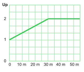
Of the three factors (difference of impedance, frequency, distance), the only one that can really be controlled is the length of cable between the SPD and the load to be protected. The greater this length, the greater the reflection.
Generally for the overvoltage fronts faced in a building, reflection phenomena are significant from 10 m and can double the voltage from 30 m (see Fig. J60).
It is necessary to install a second SPD in fine protection if the cable length exceeds 10 m between the incoming-end SPD and the equipment to be protected.
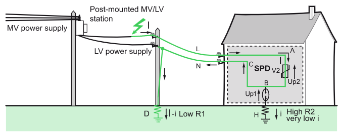
Example of lightning current in TT system
Common mode SPD between phase and PE or phase and PEN is installed whatever type of system earthing arrangement (see Fig. J61).
The neutral earthing resistor R1 used for the pylons has a lower resistance than the earthing resistor R2 used for the installation.
The lightning current will flow through circuit ABCD to earth via the easiest path. It will pass through varistors V1 and V2 in series, causing a differential voltage equal to twice the Up voltage of the SPD (Up1 + Up2) to appear at the terminals of A and C at the entrance to the installation in extreme cases.

To protect the loads between Ph and N effectively, the differential mode voltage (between A and C) must be reduced.
Another SPD architecture is therefore used (see Fig. J62)
The lightning current flows through circuit ABH which has a lower impedance than circuit ABCD, as the impedance of the component used between B and H is null (gas filled spark gap). In this case, the differential voltage is equal to the residual voltage of the SPD (Up2).
Source URL: https://www.electrical-installation.org/enwiki/Surge_protection_technical_supplements
