Published by Wiesława MALSKA1, Anna KOZIOROWSKA2,3, Dariusz SOBCZYŃSKI1
Rzeszow University of Technology, The Faculty of Electrical and Computer Engineering,
Department of Power Electronics and Power Engineering (1)
University of Rzeszow, Department of Mathematics – Natural Sciences, Institute of Technics (2)
Institute of Applied Biotechnology and Basic Science University of Rzeszow, (3)
Abstract. Specialized laboratory equipment, often uses power converters, which are the source of higher harmonics. These devices, depending on their functions, are composed of several additional elements (such as UV light, a heater).They also enable the speed adjustment .Mostly, these are low-power devices used in laboratories, scientific research units engaged in research and teaching.
Streszczenie. Specjalizowane urządzenia laboratoryjne, bardzo często wykorzystują przekształtniki energoelektroniczne, które są źródłem wyższych harmonicznych. Urządzenia te w zależności od swoich funkcji składają się z kilku dodatkowych elementów (np. lampa UV, grzałka), a także umożliwiają regulację prędkości. Najczęściej są to urządzenia małej mocy i stosowane są w laboratoriach badawczo-naukowych jednostek prowadzących badania naukowe i zajęcia dydaktyczne. (Specjalizowane wyposażenie laboratorium biotechnologicznego z uwzględnieniem wyższych harmonicznych)
Słowa kluczowe: odkształcenia napięcia i prądu, wyższe harmoniczne, specjalizowane urządzenia laboratoryjne
Keywords: Voltage and Current Distortion, Higher Harmonics, specialized laboratory equipment
Introduction
Commonly used non-linear devices are the sources of higher harmonics, which increase the apparent power of devices and power losses in the power lines, but information about their impact on the supply network of specialized laboratory equipment can rarely be found in the literature. Higher harmonics also cause electromagnetic interference and sometimes strong resonance phenomena. In this way, they adversely affect the operation of security systems, automation and control systems, robot and communication, as well as other receivers of electricity. The results are economic losses caused by decrease in reliability and service life of these devices. Correct operation of electrical equipment is possible under the right conditions, in terms of the guarantee by the manufacturer of the device. They mainly concern the environment in which the device will operate, the quality of the supply line and the level of electromagnetic interference affecting the inverter. At the same time power electronic equipment should not be cumbersome to operate, and in particular it should not adversely affect the operation of other devices – in particular electrical equipment [2,3,4].
We can talk about the power quality standard, if in the place of observation (measurement) the voltage curve is exactly sinusoidal, the nominal frequency and its rms value is equal to the rated voltage. In practice, this ideal situation is not available and necessarily power quality is considered acceptable if the deviation from the standard of the quality is not adverse for the selected device (do not interfere with its operation). A growing number of different sets connected to the power system affects the intensity of the interaction between them, which in the end leads to a deterioration of their electrical conditions of operation. This interaction is mediated by mutual galvanic coupling from the supply network and the electromagnetic waves emitted by the receivers (electromagnetic interference – EMI) [5,6,7,8,9]. Converters adversely affect a supply line and are a source of electromagnetic interference. They are susceptible to interference reaching from the power supply and from electromagnetic fields generated in their main circuits, and generated by other adjacent equipment.
Electric operating conditions of power electronic devices are determined primarily by parameters of AC or DC supply line, the intensity of different types of electromagnetic interference and type of load. Hence the need to take into account the nature of the operation of specialized laboratory equipment, which is often found in the same room in a laboratory, and is supplied from the same power network. It should be noted that operating time of specialized equipment varies and depends on whether the measurement tests are done and how many instruments work at the same time. The target scientific functions are different, depending on the purpose of the study and the type of a device, but nevertheless all the devices are supplied from the same power network [10,11,12,13,14,15,16,20]. Therefore, knowledge of the characteristics of these devices is important.
The paper shows the results of measurement tests of the impact on a supply network of two devices – a laminar chamber and a thermal cycler. The structure and appropriate control of the device are important to reduce or minimize the negative effects of this type of equipment to power supply from the point of view of a power network. The research was engaged in the laboratory of the Institute of Applied Biotechnology and Basic Sciences University of Rzeszow in Werynia.
Characteristics of the laboratory equipment
The thermal cycler is an electric device which controls the temperature. The samples placed in the device are alternately heated and cooled in accordance with the requirements of the methodology used in the PCR (Polymerase Chain Reaction) e.g. to reproductive DNA chains in the laboratory conditions. PCR has many applications – for example, in the study of genes (gene cloning, characterization of gene expression), in the identification of missing persons, in establishing paternity and paleontology. The thermal cycler, which is a basic device used in molecular biology laboratories, offers fast temperature control.
Two models of thermal cycler were tested – Mastercycler Personal and Mastercycler Gradient. The state of start-up and increase of the temperature as well as a condition of stable operation of equipment were measured.
A chamber with laminar air flow is electrical equipment used in molecular biology laboratories in order to protect the sample from contamination. Through the use of biosafety cabinets sterile working area in the laboratory is obtained.

They are used during sterile work in microbiology and in vitro culture of plant and animal cells. They protect the environment from contamination during the work with the use of hazardous materials (eg, infectious bacteria and viruses, GMOs). The cells in the culture require providing an environment simulating the natural one. One of the factors is a sterile environment for growth. It should provide adequate temperature and humidity. The laminar chamber provides cells with the sterile environment while working with them. The air in the chamber is passed through a special filter, which provides the purification of bacterial or fungal spores which cause the infection arising [1].
The various states of a Thermo Scientific laminar chamber were studied. This is a chamber of class II safety designed to work with infectious material (tissue, blood, viruses, bacteria) and pure material requiring protection (cell culture), with a capacity of 0.8 kW. It has two filters – the main and in the air outlet. The efficiency of the filter is 99.999% for particles of 0,3μm. It has the microprocessor control which allows controlling both the flow of air in the working chamber and the use of filters. The laminar chamber is supplied from single-phase. At first the study included the start-up state – the preparation of chamber to work. Then the operating conditions when using the blower and the UV lamp were studied.
Results of laboratory tests
In order to analyze the work of selected biomedical laboratory equipment for selected indicators and power quality parameters, selected quantities were measured in the laboratory of the Centre of Applied Biotechnology and Basic Sciences, where the equipment is used for scientific research. As the measure of evaluation of harmonic distortion HD (Individual Harmonic Distortion) and Total Harmonic Distortion THD [17,18, 19] were assumed.
Total Harmonic Distortion factor THD (voltage or current) is defined as the ratio of the rms value calculated excluding the first harmonic (it is assumed that the constant is zero) to the value of the first harmonic effective:
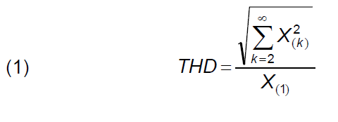
where X(k) was determined as the rms value of the k-th harmonic of the signal x(t).
The contribution of each harmonic in the final shape is defined as an individual signal distortion factor HD (current or voltage) and is calculated from the formula:

where: X(k) – rms value of the harmonic of k order, k = 2, 3, 4, …, n; n – number of harmonic taken into account in analysis, in accordance with PN-EN 50160 n=40; X(1) – rms value of fundamental harmonic.
The paper also contains the rms value of current waveforms under varying operating conditions, to characterize the changes in power consumption.
Figures 1-2 show the waveforms of rms values of current of thermal cycler in various stages of work, from preparation to work with the heater on and off, as well as start-up to a normal, stable operation.


Waveforms of rms current does not allow for an evaluation of the distortion, so in the following section there is provided the analysis of the components of distortion. Considerations concern a variety of operating conditions of biomedical laboratory devices.
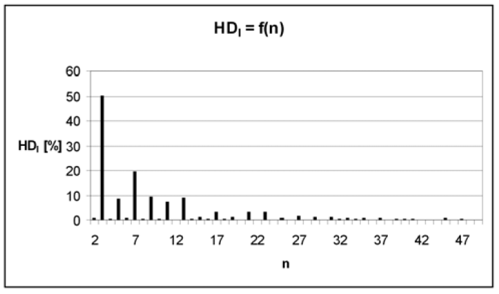
The individual factor of supply current distortion of a thermocycler (Mastercykler Gradient type) shown in Figure 3 for the standby operating status, clearly shows the large distortion of the supply current, and the value of the THD of current is 75.6% (the value of the voltage THD was 1.74%)

Large values of THD factor indicate high amplitudes of higher harmonics (mainly harmonic: the third, fifth, eleventh, thirteenth, etc.).
Figures 4-5 contain an individual supply current distortion factor for the thermal cycler at 58 °C (operation with heater turned on) and steady state (“Second” heat cycle (high time constant)).

Visible differences on the graph of HD factor in fig. 4 and fig. 5 show different ways of control dependent on a thermocycler mode of operation, in particular, the setting and a way of temperature control inside the thermal cycler. THD current factor for the case of a heater turn on is 71,9% (THD of voltage is 1,88%), and for the case with second cycle of heating is 57,1%. It is related to the long duration of the temperature increase inside the thermal cycler (voltage THD 1.81%).
Figures 4-5 show high values of HD factor for individual harmonics, which demonstrate the diverse nature of the work, depending on the selected mode of operation.
For the laminar chamber, measurements for different states of work were performed – from the state of preparation to work, the inclusion of fan until the UV lamp is turned on.
Figures 6-8 show graphs of individual factor distortion HD for the laminar chamber. In Figure 6 for the standby status, current THD value in this case was 30.5% (THD for a supply voltage was 1.7%), for the case of Figure 7 THD current value was 18.9% (a value of voltage THD was 1.79%). It was the case with the fan turned on inside the laminar flow. In fig. 8 a change of HD factor value for individual harmonics is shown, for the UV lamp turn on inside the laminar chamber, and at the time of measurement value of current THD was equal to 24.8% (a value of voltage THD was 1.71%).


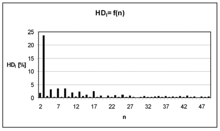
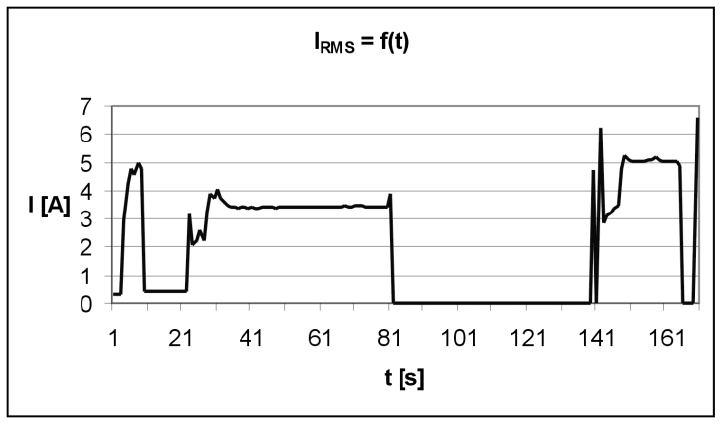
Figure 9 shows a course of rms current value of laminar chamber during 170 seconds of work.
The first seconds are a start-up, pumping the air out of the chamber, and in the 148 second the UV lamp was turned on.
Summary
Based on experimental studies using a Yokogawa WT 500 power meter (which allows the simultaneous measurement of voltage, current, power, and total harmonic distortion), the evaluation of harmonics generated to the power supply by two selected specialized laboratory items of equipment can be carried out.
The first analyzed device – the thermocycler – depending on the nature of the work (as start-up, the status of temperature control (switching on and off the heater) is an example of the so-called. “restless” receiver. The next analyzed device – a laminar chamber is the same type of a device (the change of current distortion is visible in changes of the operating mode (turn on or off the fan, turn on or off the UV lamp, keeping a constant temperature level. Both devices placed in laboratories of Centre of Applied Biotechnology and Basic Sciences are used every day for about 10 hours.
Therefore, they are a source of harmonics generated to the supply network. At the same time, the same network supplies highly specialized unique devices for molecular analysis, for example Real Time PCR, sequencer, spectrophotometers and chromatographs. Research related to the evaluation of specialized biomedical laboratory influence on supply network continues. The results of these studies will be presented in subsequent papers. This work aims to assess the level of current distortion generated in the whole research biotechnology laboratory and development of the manner of their limitations.
The study was performed within the project Centre of Applied Biotechnology and Basic Sciences supported by the Operational Programme Development of Eastern Poland 2007-2013, NoPOPW.01.03.00-18-018/09.
REFERENCES
[1] Kalinowska K., Ogórek R., Baran E. – Diagnostyka mikologiczna: wczoraj i dziś. Od mikroskopu do termocyklera, Mikologia Lekarska 2011, 18 (3): 156-158
[2] Barlik R., Nowak M.: Jakość energii elektrycznej – stanobecny i perspektywy. Przegląd Elektrotechniczny , nr 7-8 2005,
[3] Hanzelka Z.: Rozważania o jakości energii elektrycznej. Elektroinstalator nr 9/2001- 2/2002
[4] Malska W., Łatka M.: Wpływ odbiorników nieliniowych na parametry jakości energii elektrycznej, Wiadomościi Elektrotechniczne, nr 10, 2007r.
[5] Nowak M., Barlik R.: Poradnik inżyniera energoelektronika, WNT, Warszawa 1998
[6] Paice Derek A.: Power electronic converter harmonics, IEEE Press, New York 1996
[7] Piróg S.: Energoelektronika: układy o komutacji sieciowej i o komutacji twardej), Uczelniane Wydawnictwa Naukowo-Dydaktyczne, AGH, 2006
[8] Strzelecki R., Supronowicz H.: Filtracja harmonicznych w sieciach zasilających prądu przemiennego, Postępy Napędu Elektrycznego, 1998
[9] Bartman J., Koziorowska A., Kuryło K., Malska W. – Analiza rzeczywistych parametrów sygnałów elektrycznych zasilających układy napędowe pomp wodociągowych – Przegląd Elektrotechniczny, 2011/8, str. 8-11
[10] Ustawa z dnia 10 kwietnia 1997 r. Prawo energetyczne. Dz.U. nr 54, poz. 348 z późniejszymi zmianami
[11] Norma PN-EN/50160 Parametry napięcia zasilającego w publicznych sieciach rozdzielczych. PKN 1998
[12] Rozporządzenie ministra gospodarki i pracy z dnia 20 grudnia 2004 r. w sprawie szczegółowych warunków przyłączenia do sieci elektroenergetycznych, ruchu i eksploatacji tych sieci. Dz.U. z 06.01.2005
[13] PN-EN 50160:2002 Parametry napięcia zasilającego w publicznych sieciach rozdzielczych.
[14] PN-T-03501:1998 Kompatybilność elektromagnetyczna (EMC). Dopuszczalne poziomy. Ograniczanie wahań napięcia i migotania światła powodowanych przez odbiorniki o prądzie znamionowym większym niż 16 A, w sieciach zasilających niskiego napięcia.
[15] PN-EN 61000-3-2:1997 Kompatybilność elektromagnetyczna (EMC). Dopuszczalne poziomy. Dopuszczalne poziomy emisji harmonicznych prądu (fazowy prąd zasilający odbiornika mniejszy lub rowny 16 A).
[16] PN-EN 61000-3-3:1997/A1:2002 (U) Kompatybilność elektromagnetyczna (EMC). Dopuszczalne poziomy. Ograniczanie wahań napięcia
[17] PN-EN 61000-4-7:1998 Kompatybilność elektromagnetyczna (EMC). Metody badań i pomiarow. Ogólny przewodnik dotyczący pomiarów harmonicznych i interharmonicznych oraz stosowanych do tego celu przyrządow dla sieci zasilających i przyłączonych do nich urządzeń.
[18] PN-EN 61000-4-11:1997 Kompatybilność elektromagnetyczna (EMC). Metody badań i pomiarow.
Badania odporności na zapady napięcia,krotkie przerwy i zmiany napięcia.
[19] PN-EN 61000-4-14:2002 Kompatybilność elektromagnetyczna (EMC). Metody badań i pomiarow. Badanie odporności na wahania napięcia.
[20] PN-EN 61000-4-28:2004 Kompatybilność elektromagnetyczna (EMC). Metody badań i pomiarow. Badanie odporności na zmiany częstotliwości sieci zasilającej.
Authors: dr inż. Wiesława Malska, Politechnika Rzeszowska, Wydział Elektrotechniki i Informatyki, Katedra Energoelektroniki i Elektroenergetyki, al. Powstańców Warszawy 12, E-mail: wmalska@prz.edu.pl;
dr inż. Anna Koziorowska, Uniwersytet Rzeszowski, Instytut Techniki, al. Rejtana 16c, 35-959 Rzeszów, E-mail: akozioro@univ.rzeszow.pl;
dr inż. Dariusz Sobczyński, Politechnika Rzeszowska, Wydział Elektrotechniki i Informatyki, Katedra Energoelektroniki i Elektroenergetyki, al. Powstańców Warszawy 12, 35-959 Rzeszów, E-mail: dsobczyn@prz.edu.pl
Source & Publisher Item Identifier: PRZEGLĄD ELEKTROTECHNICZNY, ISSN 0033-2097, R. 89 NR 10/2013
