Published by Electrotek Concepts, Inc., PQSoft Case Study: Industrial Customer IEEE Std. 519 Compliance Evaluation, Document ID: PQS1003, Date: March 15, 2010.
Abstract: Utility power system harmonic problems can often be solved using a comprehensive approach including site surveys, harmonic measurements, and computer simulations.
This case study presents the results for an industrial customer IEEE Std. 519 compliance evaluation. The simulations were completed using the SuperHarm program. The results showed a harmonic resonance when the customer power factor correction capacitor banks were in service. The voltage distortion levels were mostly within the specified limits.
INTRODUCTION
An industrial customer IEEE Std. 519 compliance evaluation study was completed for the system shown in Figure 1. The simulation analysis was completed using the SuperHarm program. The accuracy of the simulation model was verified using three-phase and single-line-to-ground fault currents and other steady-state quantities.
The circuit modeled for the case involved a 12.5kV utility distribution substation supplying two 1,500 kVA customer step-down transformers. Each customer has a switchable 200 kVAr, 480-volt capacitor bank and a variety of nonlinear loads.
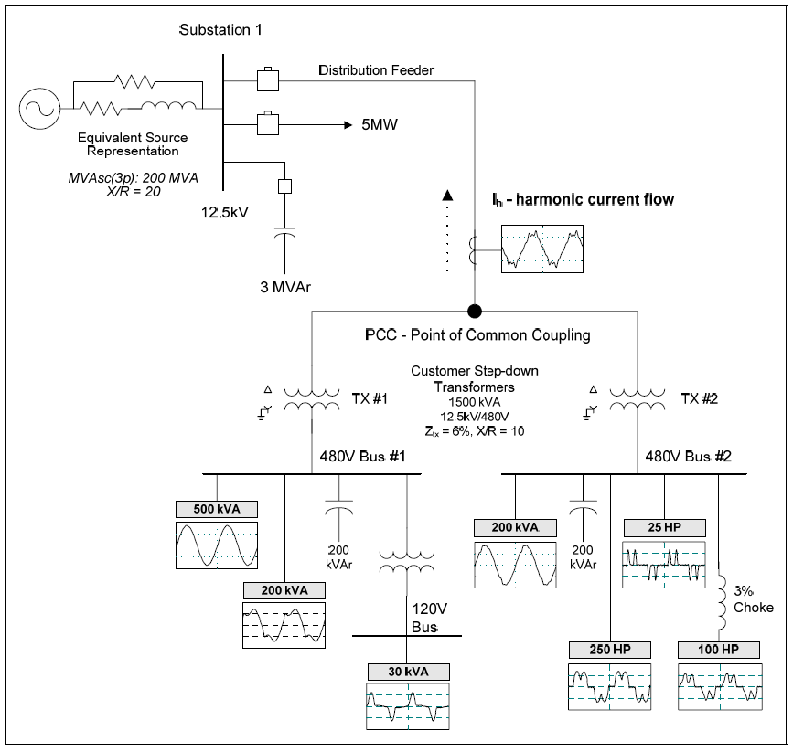
SIMULATION RESULTS
Relevant utility system and customer data for the case included:
Short-circuit MVA at 12.4kV bus: 200.0 MVA
Substation capacitor bank rating: 3.0 MVAr
Feeder load: 5.0 MW
Distribution feeder impedance: 0.2 Ω
Short-circuit MVA at PCC: 158 MVA (Isc = 7,298 A)
Customer capacitor bank ratings: 200 kVAr
Miscellaneous linear load: 700 kVA
Customer average maximum demand load: 974 kVA (IL = 45 A)
Fluorescent lighting (ITHD = 21.7%): 200 kVA
DC drive (ITHD = 35.3%): 250 hp
PWM ASD (no choke – ITHD = 130.8%): 25 hp
PWM ASD (with 3% choke – ITHD = 45.1%): 100 hp
Switch mode power supplies (ITHD = 77.2%): 30 kVA
Figure 2 shows the results for the three frequency scan simulations. Case #1 was the base case with no capacitor banks included in the model. Case #2 was the case with the 200 kVAr capacitor banks on each customer 480 volt bus. Case #3 was the case with the 200 kVAr capacitor banks reconfigured as 4.7th harmonic filters. The parallel resonance for Case #2 was about 680 Hz.

Table 1 summarizes the results for the three distortion simulations. The table includes the simulated voltage total harmonic distortion (THD) at the five buses for the three different operating conditions. Only one of the cases exceeded the voltage limitation of 5% THD.
Table 1 – Summary of the Simulated Voltage Distortion Results
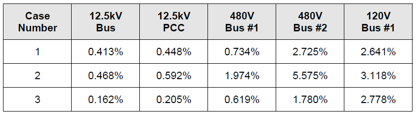
Table 2 shows the harmonic currents limits from IEEE Std. 519 that may be used for industrial customers. The ratio of the short-circuit MVA at the point of common coupling (PCC) to the average maximum demand load is approximately 162 (158 MVA / 974 kVA). That means that the fourth row of the table was used to evaluate the harmonic currents at the PCC for the three different operating conditions.
Table 2 – IEEE Std. 519 Current Limits for Utility Customers

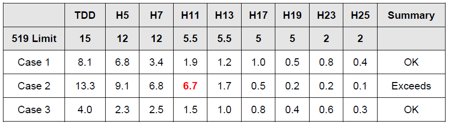
Table 3 summarizes the results of the harmonic current compliance analysis for the three simulated cases. The only condition that exceeded the limitation is the 11th harmonic component for Case #2 which represents the condition with the two 200 kVAr capacitor banks at the customer low voltage buses. The results for Case #3 show that converting the 200 kVAr capacitor banks into 4.7th harmonic filters reduced the harmonic current levels below the specified limitation.
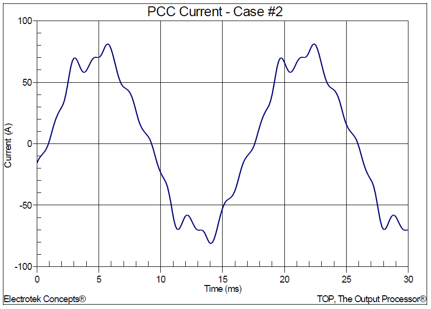
Figure 3 shows the corresponding simulated point of common coupling (PCC) current waveform for Case #2. The waveform was created using an inverse DFT with 256 points per cycle.
Table 3 – Summary of Harmonic Current Limit Compliance
SUMMARY
This case study summarizes the results for an industrial customer IEEE Std. 519 compliance evaluation. The simulation results showed an 11th harmonic resonance when the customer power factor correction capacitor banks were in service. The voltage distortion levels were mostly within the specified limits.
The initial solution might seem to be to install an 11th harmonic filter; however, passive filters should be tuned below the lowest significant harmonic present. In this case, that was the 5th harmonic. Therefore, the current distortion evaluation shows that current distortion limits can be achieved by converting the customer capacitor banks into 4.7th harmonic filters.
REFERENCES
1. Power System Harmonics, IEEE Tutorial Course, 84 EH0221-2-PWR, 1984.
2. IEEE Recommended Practice for Monitoring Electric Power Quality,” IEEE Std. 1159-1995, IEEE, October 1995, ISBN: 1-55937-549-3.
3. IEEE Recommended Practices and Requirements for Harmonic Control in Electrical Power Systems, IEEE Std. 519-1992, IEEE, ISBN: 1-5593-7239-7.
RELATED STANDARDS
IEEE Std. 519-1992
IEEE Std. 1159-1995
GLOSSARY AND ACRONYMS
ASD: Adjustable-Speed Drive
CF: Crest Factor
DFT: Discreet Fourier Transform
DPF: Displacement Power Factor
PCC: Point of Common Coupling
PF: Power Factor
PWM: Pulse Width Modulation
TDD: Total Demand Distortion
THD: Total Harmonic Distortion
TPF: True Power Factor
