Published by Bronisław TOMCZUK, Dariusz KOTERAS, Jan ZIMON, Andrzej WAINDOK
Opole University of Technology, Department of Industrial Electrical Engineering
Abstract. The Field-Circuit Method (FCM) and the new Modified Time Stepping Finite Element Method (MTSF) as well as classical Time Stepping Finite Element Method (TSF) have been used for the transient current calculations in transformers. The execution times for MTSF and TSF methods have been compared. The novel method (MTSF) is about two times faster than the classical (TSF) method. Two constructions of the 1-phase transformer have been studied. The first one is an amorphous modular transformer (T1) and the second one is the transformer with laminated carbon steel core (T2). The calculated inrush currents were compared with the measured ones.
Streszczenie Do obliczeń przebiegów czasowych prądów w transformatorach wykorzystano: Metodę Polowo-Obwodową (MPO), Zmodyfikowaną Metodę Kroku Czasowego (ZMKC) oraz klasyczną Metodę Kroku Czasowego. Porównano czasy obliczeń dla klasycznej Metody Kroku Czasowego (MKC) oraz dla ZMKC wykorzystującej dwuwymiarową analizę polową. ZMKC jest około dwa razy szybsza od MKC. Analizowano dwa 1-fazowe transformatory. Pierwszy to transformator amorficzny budowy modułowej T1, natomiast drugi to transformator tradycyjny z rdzeniem z blachy elektrotechnicznej T2. Otrzymano dobrą zgodność obliczeń z pomiarami. (Obliczenia przebiegów czasowych prądów w transformatorach przy użyciu metod polowo-obwodowych).
Słowa kluczowe: Metoda Kroku Czasowego, Metoda Polowo-Obwodowa, prąd załączania transformatora.
Keywords: Modified Time Stepping Method, Field-Circuit Method, inrush current of the transformer.
Introduction
The small power transformers are switch on/off in their operation. In the switching on moments a non-sinusoidal transient inrush current arises. In some cases, the magnitude of the inrush current is several times higher than the operational load current. Its value depends mostly on the voltage magnitude of the supplying source and the residual flux in the transformer core, as well as the current flux derivative called dynamic inductance Ld [5]. The benefits of the computer simulations and the current determination are well recognized. Knowledge of their values is also important for correct determination of the shelters parameters [1]. A accurate approximation of the inrush current requires detailed information regarding the transformer parameters [2]. If its physical model is approachable, the equivalent circuit parameters can be simply obtained from its measurements. However, during the transformer designing they can be obtained from computer simulations, e.g. from magnetic field calculations [3, 4].
The transients of transformers were analyzed in many works e.g. [3, 5]. Not always the residual (remanent) flux is considered for the transformer soft magnetic material core. In some cases, the hysteresis effects were also taken into account [3]. In this work we carried out the calculations using the equivalent circuit parameters, which have been obtained from numerical analysis. We included different values of the residual flux.
Using magnetic field analysis, the non-linear characteristic of the dynamic inductance, as a function of magnetizing current, has been determined. Also, the leakage inductances have been computed. In the computations the material characteristics have been included and the magnetic residual flux has been indirectly taken into account for the initial value of the magnetizing current fixing.
In this work have been compared commercial programs with program created by authors as part of the grant of Polish Ministry of Science and Higher Education. In this algorithm is used modified Time Stepping Method. This modification consists in using calculated magnetic flux values in every step to determine inductance.
Analyzed objects
To investigate the inrush currents, the new construction of 1-phase transformer with amorphous modular core (T1) and a conventional construction of 1-phase small power transformer (T2) have been chosen [5] (Fig. 1). Each column of the amorphous transformer consists of two hollow cylinders (toroids). Its yokes have rectangular shape with two rounded thinner sides (Fig. 1a) [6, 7]. Contrary to the T1, the T2 transformer core is assembled from packages of thin sheets high-grade steel. In Fig. 1, the main dimensions of the transformers and the assumed Cartesian coordination systems are shown. For the T1 transformer, the turn number of the windings is N=232, while for the conventional one (T2), the winding is wounded with N=182 turns.
Mathematical models Field-Circuit Method (FCM)
Generally, the inrush current of the transformer was analyzed by using Field-Circuit Method (FCM). In this model the calculations of the transients are based on the transformer equivalent circuit (Fig. 2), which is described by the following system of the differential equations [3, 8]:
In the expressions (1), the leakage inductance value is Ls=732 μH for T1 and Ls=177 μH for T2, the RMS value of the excitation voltage U=220 V, the coil resistance value – R=0.24 Ω for T1 and R=0.136 Ω for T2. The core losses resistances of RFe=1913 Ω (for T1) and RFe=2186 Ω (for T2) have been determined. The currents i and iμ are unknown functions. The nonlinear dynamic inductance Ld(iμ) should be determined by the finite element (FEM) calculations.
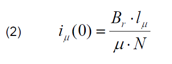
As was mentioned in the section 1, the residual flux value Br and the flux magnetic path lμ, influence on the current value iμ
The leakage inductance Ls value of the transformer winding has been determined by using the field analysis under short-circuit state. Resistance RFe has been determined from measurements under no-load state, whereas the dynamic inductance Ld curve has been created using the field models. The assumed excitation current values in the models has changed from 0.2 to 100 A. In Fig.3 the dynamic inductance verso excitation current is presented.
Time Stepping FEM (TSF) and its modification –MTSF method
In the second mathematical model (called MTSF) the governing expressions for the magnetic field is represented by Maxwell’s equation with the magnetic vector potential →A . If the eddy currents in the iron core are neglected, the magnetic field can be expressed by the partial differential equation (PDE)
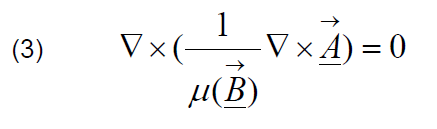
where μ(→B) is the nonlinear permeability of the material.
In the area of the windings, the magnetic field can be governed by the equation
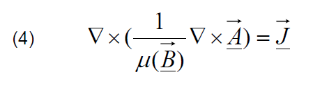
where →J is the total current density.
The Galerkin’s approach is the most popular method for matrix of elements formulation. In this proposed model, the weighting functions are the same as the shape functions for this particular weighted residual method. According to the Galerkin’s method, the magnetic vector potential can be expressed as
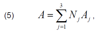
where Nj are the element shape functions and the Aj are the approximations of the vector potential at the nodes of the elements. Thus, the formulation for the field, in the current currying regions, is expressed by:
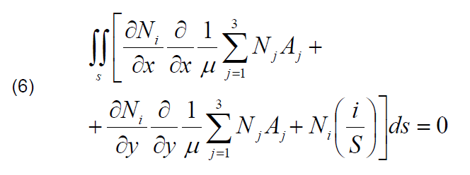
For the other subregions of the transformer the functional is expressed
Taking into account the average length path l of the flux in the coil and its cross-section S, the electric circuit can be described by the:

The integrals in (8) refer the region S1 with the positive direction of the excitation current and the region S2 with the negative current direction.
Contrary to the commercial computational methods of the time variable FEM [9], we have solved the equation (8) with our software. For the field calculation with the discretized functionals we use the FEMM software. In this modeling method the 2D field calculations have been done. In the case of amorphous transformer, according to its geometry, it is difficult to obtain real magnetic field distribution in 2D. Therefore, depth of this object was fitted for magnetic flux value.
Our method characterizes simplicity and multitask system. Thus the computational platform don’t need to execute so much iterations like in the classic TSF algorithm. Contrary to the TSF method, the values of the dynamic inductance, which concern the field values in the step “i”, are stored in the separate matrix, which is located in the RAM memory. Thus, we don’t need to compute integrals within the eq. 8 in each step of the computational process. It is a great advantage of the MTSF, because only at several time steps the problem must be solved.
Calculation results | Amorphous transformer (T1) – inrush currents
In this paper the supplying voltage for the primary winding under the no load state of the transformer has been assumed. However, the magnetic flux density distribution has been calculated for many values of the current excitation. For example, in Fig. 4 the flux density is presented. The field analysis is devoted to the dynamic inductance determination.

In Figs. 5 and 6 the comparison of the calculated and measured inrush current waves for T1 transformer, under excitation phase φ=0 and φ=90° have been presented. The FCM method and the MTSF one give similar results. However, the first one is about 1.5 times faster. In the case of the φ=90°, both models give almost the same inrush current waves (Fig. 6).
For our investigations, in the analyzed amorphous core the maximal value of the residual magnetic flux density Br reaches only 0.2 T. In this paper are presented transient inrush current waves for two values of the residual flux density: Br=0.1 T and Br=0.2 T (Figs. 7a and 7b). Increasing the residual flux density value causes increasing of the inrush current peak value. In the case of Br=0.1 T the current peak value is 50% higher than for the net value of the Br. In the second case (Br=0.2 T), the current peak reaches i=65 A.
Inrush currents for the conventional transformer (T2)
We also calculated the inrush currents for the conventional construction of the transformer T2. The calculations have been executed for three different values of the core residual flux density. The assumed switching on phase φ=0 has been chosen. The comparison of the calculation results for two computing methods shows, that the MTSF method is more adequate for transient calculations, (Figs. 8 and 9). It can be observed a fine attenuation of the current waves in the case Br=1.2 T. The MTSF calculation method gives more accurate results comparing to the simplified field-circuit method (Fig. 8).
Fig. 9 shows the calculated current waves for two values of the residual flux density: Br=0 T and Br=0.8 T. We can observe that the residual flux density strongly influenced on the inrush current. The current values in the first times period of the current wave are about one hundred times greater than those simulated without the residual magnetism.
The calculations of the currents have been executed with a TSF method, as well. The method is included in many commercial FEM applications. To compare the calculation times for all the methods, we also computed the problem using FCM model. The MTSF method was two times faster than the TSF one for the inrush current calculations (Tab. 1). The computations have been done with using the AMD64 3200+ processor and 3GB of RAM.
Table 1. Compared CPU times for analyzed T2 transformer
| FCM | TSF | MTSF | |
| CPU time [s] | 543 | 1782 | 846 |
Conclusions
The field-circuit method (FCM) and time stepping FEM (MTSF) for simulation of the inrush current waves in the two transformers have been studied. In the case of amorphous transformer T1 both methods give similar results. However, for T2 transformer analysis, the more accurate results arise from the MTSF method. First of all its is due to time discetization within numerical process.
The MTSF has been compared with the commercial TSF, [10]. The CPU time is about two times shorter for the MTSF, which validates the algorithm [11].
The influence of the residual flux on the maximum values of the current waves is higher in the case of conventional transformer, compared to the amorphous one (Figs. 6 and 7). It is mostly due to the air gaps length in the modular construction. Thus, the saturation of the transformer T1 core is considerable lower than the saturation of the T2 transformer core.
The calculation method presented in this work has been validated by measurements of the single-phase transformers. We observed relatively good conformity between computed and measured current waves [Figs. 5, 6, 8]. The differences between calculation and measurement results arise from the simplifications in the field analysis and measurement errors. The main difficulty is precisely determination of residual flux value which has significant influence on inrush current. For example, the residual flux is difficult for testing and contributes to the errors of our method, as well. Additionally, it is impossible to determine exactly the air gap length in the prototype tests. Moreover, we can see that the inrush current for amorphous modular transformer has maximal value several times lower compared to the conventional one.
This paper is partially supported by the Polish Ministry of Science and Higher Education under grant no. N N510 533739.
REFERENCES
[1] Jezierski E.: Transformers, WNT Warszawa, (1983) (in Polish).
[2] Grigsby L.L. (Ed.): The Electric Power Engineering Handbook, CRC Press LLC, Boca Raton, (2001).
[3] Zakrzewski K, Tomczuk B., Magnetic Field Analysis and Leakage Inductance Calculations in Current Transformers by Means of 3-D Integral Methods, IEEE Trans. on Magn., Vol. 32, (1996), no. 3, 1637-1640.
[4] Zakrzewski K.: Power effect in magnetic lamination taking into account elliptical hysteresis approach, ISEF’07, Prague, Czech Republic, 13-15 IX, 2007, no. 024 (on CD).
[5] Tomczuk B., Koteras D., Zimon J., Waindok A.: Polowa analiza siłowników elektromagnetycznych i transformatorów, Pomiary Automatyka Kontrola,(2011), no. 3, 264-268, (in Polish)
[6] Tomczuk B, Koteras D.: Eddy current losses in magnetic circuit with solid ferromagnetics. Electrical Review, (2010), no 4, 180-183.
[7] Tomczuk B., Koteras D.: Magnetic Flux Distribution in the Amorphous Modular Transformers, Journal of Magnetism and Magnetic Materials , vol. 323, (2011), no. 12, 1611-1615
[8] Koteras D.: Magnetic field analysis in modular design transformers with amorphous cores, doctoral thesis, Opole University of Technology, (2006).
[9] Meeker D.: FEMM 4.2 User’s Guide, Charlotteville, USA, (2009).
[10] Maxwell 2D v12 User’s Guide, Piscataway, USA, (2009).
[11] Tomczuk B, Koteras D., Zimon J., Waindok A.: Comparison of numerical methods for current determination under no-load transformers, Zeszyty Problemowe-Maszyny Elektryczne, Branżowy Ośrodek Badawczo-Rozwojowy Maszyn Elektrycznych Komel, Katowice, (2011), no 92, 145-150.
Authors: Prof. Bronisław Tomczuk, (Ph.D., D.Sc.) Opole University of Technology, Industrial Electrical Engineering Chair, ul. Luboszycka 7, 45-036 Opole, E-mail: b.tomczuk@po.opole.pl, Dariusz Koteras, (Ph.D., Eng.), address as above, d.koteras@po.opole.pl, Jan Zimon (Ph.D., Eng.), address as above, j.zimon@po.opole.pl,, Andrzej Waindok (Ph.D., Eng.), address as above, a.waindok@po.opole.pl,.
Source & Publisher Item Identifier: PRZEGLĄD ELEKTROTECHNICZNY (Electrical Review), ISSN 0033-2097, R. 87 NR 11/2011
