Published by Artur J. MORADEWICZ, Instytut Elektrotechniki
Abstract. The element of infrastructure that provides a connection between an electric vehicle (EV) and a depleted battery and electric source that will charge/discharge these batteries is the Electric Vehicle Service Equipment (EVSE). Recently, the interest of electric vehicles and their charging infrastructure has been the subject of extensive research and development in the world. The infrastructure for charging electric vehicles (EV) will be a key factor in ensuring a smooth transition from conventional mobility to e-mobility. The paper focuses the present charging standards and concept for future EV charging solution. The article touches the problem associated with bidirectional EV chargers which open the way for V2G technology and stationary or dynamic contactless inductive charging which open the way for automated driving EV technology. (Pokładowe i zewnętrzne ładowarki pojazdów elektrycznych).
Streszczenie. Element infrastruktury zapewniający połączenie między pojazdem elektrycznym (EV) a baterią i źródłem elektrycznym, które ładuje / rozładowuje te akumulatory, to sprzęt do obsługi pojazdów elektrycznych (EVSE). Ostatnio zainteresowanie pojazdami elektrycznymi i infrastrukturą ich ładowania jest przedmiotem intensywnych badań oraz rozwoju na świecie. Infrastruktura do ładowania pojazdów elektrycznych (EV) będzie wkrótce kluczowym czynnikiem zapewniającym płynne przejście od konwencjonalnej mobilności do e-mobilności. Artykuł skupia się na obecnych standardach ładowania i koncepcji przyszłego rozwiązania ładowania akumulatorów EV. Porusza również problem dwukierunkowych ładowarek EV, które otwierają drogę technologii V2G oraz stacjonarnego lub dynamicznego bezstykowego ładowania indukcyjnego, które otwiera drogę dla zautomatyzowanej technologii zasilania EV w czasie jazdy.
Słowa kluczowe: osprzęt elektryczny do obsługi pojazdów, ładowanie pojazdów elektrycznych, dwukierunkowe ładowarki EV, stacjonarne / dynamiczne bezstykowe ładowanie indukcyjne.
Keywords: Electric Vehicle Service Equipment (EVSE), charging electric vehicles, bidirectional EV chargers, stationary / dynamic contactless inductive charging.
Introduction
The interest in electric vehicles and their charging systems is in the focus of not only large automotive companies, but also start-ups and energy companies that want to diversify their production. On 7th June 2016, Deputy Prime Minister of Poland, Mateusz Morawiecki, announced that the Council of Ministers will prepare an Electromobility Development Plan for Poland. The Electromobility Development Plan is to become one of the pillars of the Responsible Development Plan. It is expected to create conditions for the development of manufacturing and spreading of electric vehicles. The Ministry of Energy assumes that there will be 1 million electric vehicles on Polish roads by 2025. It will be the key component of the National Framework for the Deployment of Alternative Fuels Infrastructure that Member States are required to prepare under the Directive 2014/94/EU and notify to the European Commission by 18 November 2016. However, despite government support and significant progress in EV technology, there are still limitations to their massive use. These include, above all: -high price of electric cars (about 30-50% higher than its equivalent with an internal combustion engine), still small range based on one battery charging, long battery charging time, lack of developed battery charging infrastructure. Many of these problems help to solve advanced and modern power electronics. Therefore, the power electronics system has broadly entered electromobility in the area that can be broadly divided into three specific departments: the power station charging system architecture (in particular ultra-fast charging), battery charger systems themselves, and regulated electric drives with AC motors.
The solid-state transformer
The element of infrastructure of EV chargers that provides a connection between an electric vehicle (EV) and a depleted battery and electric source, very often implemented as energy transformers in the SST arrangement [1]. The structure of solid-state transformer (Fig. 1) in many variants, we can find in many different EV chargers. The solid-state transformer (SST) has been regarded as one of the several most emerging technologies. The basic idea of the SST is to achieve the voltage transformation at high-frequency, therefore to potentially reduce the volume and weight compared to the traditional power transformer. The 50/60-Hz ac voltage is transformed to a high frequency of tens of kilohertz, by high frequency converter, then this high-frequency voltage through the high frequency transformer is transferred to secondary side to secondary side high frequency converter [2], similarly to contactless energy transfer systems. This significantly decreased volume and weight, and finally, shaped back into the desired 50/60-Hz voltage to feed the load. This is the basic idea of SST which can be denoted HVAC/LVAC (high voltage AC/low voltage AC). Usually SST transformer is realized in more complex form HVAC/HVDC/LVDC/LVAC (high voltage AC/high voltage DC/low voltage DC/low voltage AC), in which many attractive features may be potentially achieved.
The most advanced applications of SST are units which can replace traditional transformers in electrical grids. These systems are ideally suited to became building elements of Smart Grids, because they can realize:
• bidirectional power flow
• change of power parameters – voltage and frequency regulation
• optimized energy distribution based on communications between operator and customers
• transformation of power either to AC or DC form
• replacement of mechanical switches with transistors enables fast operator reaction to the disturbances and faults in energetic grid
Besides this main field of application there are many others:
• Electric car chargers (in particular modern chargers, this structure can be used in wired and wireless chargers),
• Interfaces of renewable sources of energy
• Active filters,
• Passive power compensators,
• Frequency transformers for electric motors,
• Interfaces of local energy storage.
Currently, these structures are developed in Electrotechnical Institute mainly in terms of their application in EV chargers in various configurations, on-board chargers, external chargers as well as contactless chargers.
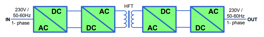
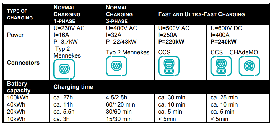
Table 1. The classification and associated parameters and types of currently used slots in the terminals wired chargers.
Stationary Off and On board chargers
The electrical equipment, which is required for connecting electric vehicles, and more specifically the electric vehicle battery to a power source is varied. The basic variation is the type of source: power from an alternating current (AC) or direct current (DC) source that will supply energy to the vehicle battery. Another internal division of these devices is their division due to the power of the charger, there are three levels:
AC Charging:
Level 1: 120V single phase, 2kW and below
Level 2: 208-240V, single phase, up to 20kW
Level 3: undefined, single or three phase
DC Charging:
Level 1: 200–450V, 20kW and below
Level 2: 200-450V, 20 to 80kW
Level 3: 200-450V, above 80kW
The infrastructure for charging electric vehicles, its costs, availability and performance are very important factors that directly affect the smoothness of the transition to electromobility and have a wider application.
There are different variations of charging technology for electric vehicles, standards, requirements, different technological approaches and different charging levels (both in terms of power and time). Table 1 shows the classification and associated parameters and types of currently used slots in the terminals wired chargers [1, 8-11].
The basic features of the off board chargers is generally higher kW transfer and included more sophisticated BMS systems, additionally: managing battery heating, communications to building/home/grid energy management systems, demand charges, removes weight from vehicle, the higher the energy transfer rate, the higher the required EVSE / vehicle conductivity.
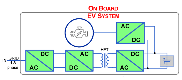
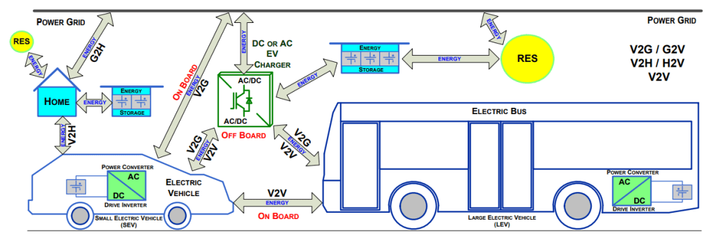
The basic features of the on board chargers is generally lower kW transfer and less concern about battery heating, BMS is managed by on board rectifier (Fig. 2). The on board chargers adds weight to vehicle. An important feature of electric vehicle chargers is if they are 2-directional, and if the energy stored in the vehicle’s battery can be transferred to the power grid, external energy storage or to another electric vehicle (Fig. 3). Vehicle to Grid (V2G) is a concept that has already been extensively described in the professional literature before EV began to appear in greater numbers on the streets of our cities. Now, however, when they are and will be more and more of them, the right cooperation EVSE and EV can become a distributed energy resource (DER) on a much larger scale and with greater significance. [3-6]. This market is just emerging, however, taking into account the number of electric vehicles and the energy stored in their batteries, will have a significant impact on system services in the power grid.
This is because the number of parked vehicles is always greater than those in motion / used. And that electric vehicles have the storage of electricity, it creates room for another and their new use. Energy storage for electric vehicles can be used by home users or large structures function as part of the power system.
Contactless chargers integrated with propulsion system
Inductive charging, also known as Inductive Power Transfer (IPT), Contactless Power Supply (CPS), Wireless Power Transfer (WPT) or Contactless Energy Transfer (CET), it is still a new technology on the market that allows users to charge PEV batteries without using a cable connection [7, 12-13]. This system consists of, among others, a charging pad (the primary side of the system installed at the power point) and the receiving pad (secondary side installed under the vehicle). Energy is transferred through a flagstone, asphalt layer, non-metallic material, water, and others.
It should be emphasized that a significant contribution to the research and development of contactless power supply systems has a sector directly related to the development of science and its applications in industry. The Electrotechnical Institute (IEL) in Warsaw has developed the 50kW contactless energy transfer (CET) system to charge large EV battery (Fig. 4). There are now working on a hybrid system combining CET system with the propulsion system. This technology, despite the initial fears, provides impressive energy transfer efficiency even for larger air gaps between the transmitter and the PEV load receiver. The successful development, implementation of wireless technology and its economical and comfortable operation is another step of its more general and broader application. Currently, work is underway on the possibility of wireless charging in the roadway (currently in separate lanes) as a method of continuous charging of the vehicle’s battery during its use on the road. Effective implementation of this technology is of particular importance to reduce the size of the battery in the vehicle, both vehicles type PEV and HEV. This explains the interest in this subject. The contactless charger of an electric vehicle is an on-board charger, thus increasing the weight of the vehicle, however, because of the numerous advantages, enjoys great interest.
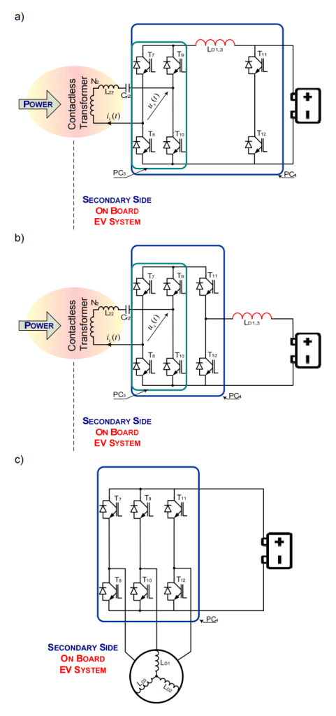
Figure 4 presents a contactless energy transfer system, whose secondary side converter is integrated with the drive inverter. The topology has supply port from single or three-phase AC source, connected by active rectifier converter PC1 as of-board part of the system. On the opposite side is the second port – energy storage as the power battery of electric vehicle. Electric motor is the third port of this concept circuit topology. The circuit should be build on the modern SiC transistors. The additional mechanical / power electronic connectors S1, 2, 3, N are required, in order to reconfigure the circuit, and switch-ON desirable operating mode. By means of appropriate configuration of the switches S1, 2, 3, N, the stator winding of the electric motor LD1, D2, D3 is disconnected or added to the circuit of the system. The topology has three operating modes that are charging and recharging mode and driving mode, PC4 converter is working. In charging and recharging operating mode converters PC2 and PC2 can operate like DAB converter. Each mode works independently. This power system should be designed to turn on or off automatically. The proposed circuit structure has two important advantages: one is galvanic insulation, the other a more convenient to use power system. The disadvantage is the more complex structure of the system due to the required additional switches. On the other hand reduce the weight of the contactless power supply system installed on board of the vehicles. The possible configurations of the structure of the system on the secondary side are shown in Figure 5. These are selected options of configuration that in the target system will depend on the type and power of the electric motor used, as well as on power electronic converters installed on the vehicle.
Conclusions
It should be emphasized that there is currently no single applicable standard of charging used, there are commonly many types of chargers with different parameters. The easiest way to charge electric vehicles is to use an additional built-in AC charger, which is an AC / DC converter with galvanic isolation. This type of solution is often used, but only as low-power chargers. The high-capacity on-board charger would significantly increase the weight of the vehicle and limit the usable space. For this reason, the built-in AC charger is usually limited to approximately 20 kW of charging power in commercial electric vehicles. An integrated charger using a combination of drive inverter and drive motor winding for charging EV batteries also increases the total weight of the vehicle, however, it gives the user much more comfort and safety of use. Currently, IEL works on reconfigular converters PC3, PC4 and their use in electric vehicles are carried out.
This work was financed from the project: TECHMATSTRATEG1/347452/1/NCBR/2017
REFERENCES
[1] “Electric Vehicle Charging Technology Analysis And Standards”, FSEC Report Number: FSEC-CR-1996-15,
[2] Xu She, Alex Q. Huang, and Rolando Burgos. “Review of Solid-State Transformer Technologies and Their Application in Power Distribution Systems”, IEEE Journal of Emerging and Selected Topics in Power Electronics, 2013
[3] Y. Fan, W. Zhu, Z. Xue, L. Zhang, Z. Zou, “A Multi-Function Conversion Technique for Vehicle-to-Grid Applications”, Energies 2015, 8, 7638-7653; doi:10.3390/en8087638,
[4] M. Kesler, M. C. Kisacikoglu, L. M. Tolbert, “Vehicle-to-Grid Reactive Power Operation Using Plug-In Electric Vehicle Bidirectional Offboard Charger”, IEEE Transactions on Industrial Electronics, vol. 61, no. 12, 2014,
[5] G. Buja, M. Bertoluzzo, C.Fontana, “Reactive Power Compensation Capabilities of V2G-Enabled Electric Vehicles”, IEEE Transactions on Power Electronics, vol. 32, no. 12, 2017,
[6] M. Yilmaz, P. T. Krein, “Review of Battery Charger Topologies, Charging Power Levels, and Infrastructure for Plug-In Electric and Hybrid Vehicles”, IEEE Transactions on Power Electronics, vol. 28, no. 5, 2012,
[7] G. R. C. Mouli, P. Venugopal, P. Bauer, “Future of Electric Vehicle Charging”, 19th International Symposium POWER ELECTRONICS Ee2017, October 19-21, 2017, Novi Sad, Serbia,
[8] SAE Standard J1772, “SAE Electric Vehicle and Plug-in Hybrid Electric Vehicle Conductive Charge Coupler,” 2010.
[9] SAE Hybrid Committee, “SAE Charging Configurations and Ratings Terminology,” 2011.
[10] “Standard IEC 62196 – Plugs, socket-outlets, vehicle connectors and vehicle inlets – Conductive charging of electric vehicles – Part 1, 2, 3”
[11] “Standard IEC 61851 – Electric vehicle conductive charging system – Part 1, 21, 22, 23, 24”
[12] Gautham Ram Chandra Mouli, Prasanth Venugopal, Pavol Bauer. “Future of electric vehicle charging”, 2017 International Symposium on Power Electronics (Ee), 2017
[13] Gan Jinhao, Wang Hui, Wang Tengxin, Wang Yubin. “An integrated topology for on-board charger and driven of electric vehicle”, IEEE International Conference on Industrial Technology (ICIT), 2017.
Author: Dr Eng. Artur Jan Moradewicz, Electrotechnical Institute, 28 Pozaryskiego St., 04-703 Warsaw, E-mail: a.moradewicz@iel.waw.pl;
Source & Publisher Item Identifier: PRZEGLĄD ELEKTROTECHNICZNY, ISSN 0033-2097, R. 95 NR 2/2019. doi:10.15199/48.2019.02.30
