Published by Ai-hua Dong, Xinlin Geng, Yi Yang, Ying Su, Mengyao Li, Henan Polytechnic University
Abstract. This paper introduces overhead line fault detection and location system as the core of industrial control computer. The combination of software and hardware, the methods of current rate of change and zero current detection are used, and so the accuracy of short circuit fault detection is improved. The features of ground phase voltage drop and the 5th harmonic current are integrated. Zigbee wireless chips are used to make into independent signal transmission system. The system has been put into operation, running in good condition.
Streszczenie. W artykule przedstawiono system detekcji i lokalizacji awarii w sieci napowietrznej do implementacji w komputerze przemysłowym. W metodzie brana jest pod uwagę m. in. wielkość zmian prądu oraz obecność prądu kolejności zerowej, co poprawiło dokładność wykrywania awarii. Zastosowano także bezprzewodowe łącze Zigbee w celu zwiększenia niezależności przesyłu sygnałów w systemie. Badania potwierdziły poprawność działania. (System lokalizacji awarii w sieciach napowietrznych z zastosowaniem sieci czujników bezprzewodowych).
Keywords: overhead lines; short-circuit fault; ground fault; online detection.
Słowa kluczowe: linie napowietrzne, zwarcie, zwarcie doziemne, detekcja online.
Introduction
As an important part of the transmission and distribution, high-voltage overhead lines often produce grounding, short circuit fault due to various reasons [1], brought great risks to the user’s safety of production. In addition, the electric power generated devastating by the strong short-circuit current, so early detection and cut off short circuit promptly, the protection equipment and switch itself can be avoided to withstand huge thermal shock and electric power , it has great significant for stable operation of the power system[2]. Currently, the line fault indicator is the main equipment for the point of failure detection and location, but the fault indicator only has fault flop function, does not has the functions of launch automatically and transfer. Also some of the existing line fault location system [3], line fault segmentation positions through the fault indicator, and the transmission using the GSM/GPRS network communication [4], multi-launch mode. Each emission point is equivalent to a mobile phone running, high operating costs, not suitable for long-distance power lines. To this end, we use the new self into an independent transmission system, ZigBee wireless transmitter module, based on the existing line fault detection method, and fault detection and signal transmission circuit as a whole, in order to achieve reliable transmission of the fault signal detection, signal, while at the same time to reduce system operating costs. The system has been installed in a supply line in our country, has good application prospects.
Basically composition of the system
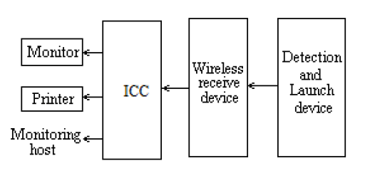
The composition of the system is shown in Fig.1. Detection and launchers mounted on the transmission line towers, including the fault detection circuit and signal transmission circuit[5], signal detection and short-circuit fault, ground fault discrimination done by the fault detection circuit and the results of the distinguish is sent to the wireless transmitter circuit. In order to save the launch of nodes, we choose the model of JN5139-Z01-M01, high-power ZigBee wireless communication module. Its basic performance: operating frequency of 2.4GHz, compatible with IEEE802.15.4 and ZigBee protocol, in the broad environment, up to 1 km communication distance; transmit power: +2.5 dBm, the emission current is less than 37mA. Each detection and launching devices set the address code, the failure of segmentation positioning can be achieved according to the address code. ZigBee wireless communication module in the device, to form an independent wireless transmission network by itself. The fault signal is transported to the substation transceiver, step by step and relay, and then the signals are received through a wired transceiver and send to the substation Industrial Control Computer (ICC), ICC be used to analyze and deal with these fault information. When failure occurs, it can achieve the audible alarm, and display, save or print the fault type and fault location, and provide the basis for the investigation of line fault and analyze the cause of the malfunction. Substation ICC will send fault information to the transceiver, through the GPRS network; the line maintenance will get the fault information by personnel phone and be notified to carry out line maintenance. In this way, taking less communication network resources communication network resources, savings in operating costs, while achieving a rapid troubleshooting and timely maintenance on the line to reduce outage time and improve the reliability of power supply system. And if necessary, the ICC of the substation can be Networked with the monitoring host of the production scheduling system through the network cable and the production scheduling system may at any time to display, print and store test data, so that the production scheduling staff can keep abreast of the operation of the line. In addition, the system also has the self-test function of the signal transmission. The ICC periodically inspects each point through response mode by the software program. It can timely comprehend the status of each device in such a way, in order to detect problems in time to ensure reliable operation of the system of signal transmission.
The principle of fault detection
A. Short-circuit fault detection principle
In order to improve the reliability of the short circuit fault detection, the system selects the short-circuit fault detection technology, based on current rate of change [6]. Its hardware circuit is shown in Fig.2. In which, the CT is a small current transformer, used to implement the sampling of the line current. Here selection of the open-type current transformer in order to facilitate installation.
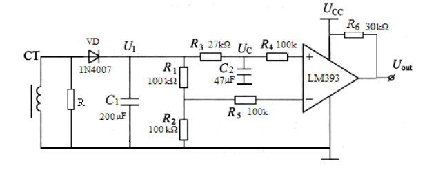
The resistance R of the resistor in parallel across the current transformer used to transform the current signal into a voltage signal. Through the diode VD rectifier and filtering capacitor C1, the AC voltage signal Change into a DC voltage signal, and then the resistance of R1, R2 partial pressure are then given to the LM393 comparator inverting input and the inverting input, the comparator is used to achieve short-circuit fault discrimination. Short-circuit fault discrimination as follows: As resistor R1 and R2 are equal, the voltage of noninverting input V+=2V-, the voltage of noninverting input is higher than the inverting input, according to the principle of the comparator the output of the comparator is high potential. When the measured line produce short-circuit fault, the current will suddenly increase, corresponding to the DC voltage signal will also suddenly increase, However, due to the termination of the noninverting input is connected a capacitor and the inverting input is not connected capacitor. Thus, when the voltage mutation occurs, the potential of inverting input terminal rise faster than the noninverting input terminal potential, causing the inverting input of the potential is higher than the noninverting terminal potential. According to the principle known of the comparator, the voltage output UOUT is low.
B. Ground fault detection principle
At present, the main method of the existing single-phase ground fault detection are [7]: zero sequence current method, capacitive current method, the first half-wave method, the fifth harmonic method and the signal injection method. When the lines of a phase to ground fault, the phase voltage will be reduced, so that the three-phase voltage will be asymmetric, usually there will be inductive load grid, line current will be distorted, produce large amounts of high-order harmonic current, appears 3, 5, 7 …… harmonics. However, since the 6 ~ 66kV distribution network belongs to the neutral point non-effectively grounded system [8]. Therefore, the third harmonic current can not be through the grid, other harmonic components accounted for a small proportion, so the 5th harmonic is the most obvious.
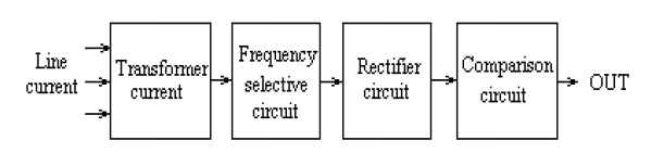
Because of this, we use the fifth harmonic current method, by detecting the line current; extract the 5th harmonic component, depending on the size of the 5th harmonic current to determine the ground fault. Detection circuit is shown in Fig.3. First, the line current is measured with a special open-type current transformer, separated the 5 harmonic by selective circuit, and then changed into a DC voltage signal by the rectifier circuit, the final outputted by the comparator circuit. There may be some higher harmonic current in the normal circuit due to the presence of nonlinear load in the circuit line. Therefore, the comparative output is used in here. According to the predicted values of the 5 harmonic current in the normal, the baseline value of the comparator is to be determined. When 5 harmonic current is greater than or equal to the reference value of the comparator, the output is high potential. It can be judged to be ground fault; otherwise, the output is low, it is nonground fault. In addition, to further improve the reliability of the ground fault detection [9], we also detect circuit phase voltage, the same as one of the necessary conditions to determine the ground fault. When the line voltage decreases, while the 5th harmonic current detection circuit outputs a high potential at this time determined to ground fault, the other cases are non-ground fault.
Installation and application
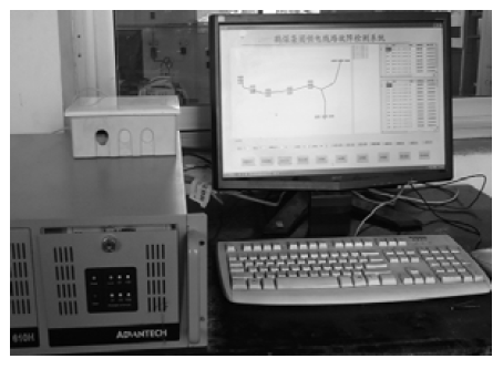
After multiple simulations detection circuit to meet the requirements, then to product the PCB, weld the component, assemble. The system is installed in a line site in Henan, run in November 2009. The total length of the installation of line about three kilometers, the line voltage rating of 6kV load current of 300A. The power supply system is the neutral point ungrounded system. According to the situation of the distance range, were selected seven detection points. The whole line to install a total of 21 fault detection devices, each test point (A, B, C) to install three detection devices. The average distance between the two detection points is about 450 meters. Detection devices onsite installation and application picture is shown in Fig.4. The host part is placed in the control room, which mainly include: industrial control micro-computers, wireless receiver, monitors, etc…The main part of the wireless receiver device is a ZigBee wireless communication module, whose role is to receive the detection signal through the wireless transmitter step by step .

The IPC gets the data wired, analyzes and processes them. Taking Kingview 6.51 software as development platform [10], the monitoring program and display with many functions are designed, such as communication, fault display, the database stores, SMS messages, etc. Home page of the picture is shown in Fig. 5.
It contains seven conversion interfaces. It contains seven conversion interfaces. Where the first three are the screens of fault display, the remaining four screens are the alarm of history, database, SMS sending and exit button. The main function of the control host as follows: (1) Fault display function. Fault display is divided into graphical display and the report shows. (2) Database function. When the system detects a failure, the relevant fault information is stored in the corresponding database. Classification to query in a database, according to the time or the type of the fault, can also generate reports, print at any time or at the setting-time. Database is also directly connected with Excel to save the information in the form of Excel tables, user-friendly; (3) SMS sending. When a fault occurs, first generate the corresponding fault information, there are time, location, fault type, and then the fault information will be sent directly to maintenance personnel mobile phones with the TC35T SMS sending module connected to the computer interface, in order to deal with failure, shorten the time of failure blackout.
Conclusions
The results of the system operation show that, The results of the system operation show that the accuracy rate of the short circuit fault detection close to 100% and accuracy rate of the ground fault detection up to 80%, and can achieve reliable transmission by relay and step, and the running costs of the system is significantly reduced, to achieve the desired goal. The safety and reliability of the power supply system becoming more demanding, urgent need for reliable fault detection and location devices. The system can be timely detection of line faults, quickly find the failures, fast processing, and rapid restoration of electricity, to reduce the outage frequency and outage time, it has great significance to improve the safety and reliability of power supply. Therefore, this technology has good prospects for promotion and application.
Acknowledgements
The work described in this paper is financially supported by science and technology innovation project of Henan Coal chemical industry group. Also, the corresponding author wishes to thank Reviewers for their useful comments and suggestions.
REFERENCES
[1] LI X, YI Z, WANG H. Study on Fault Locating for 10kV Distribution System [J]. Hubei Electric Power, 2011(35):26-28.
[2] LI Y,LU J P, LI J. Fault Location Based on On-line Computation of the Transmission LineDistributedParameters[J]. High Voltage Engineering, 2001,33(11):185-189.
[3] LIU S D,ZHENG Y,YANG F M. Line fault fast localization based on GIS fault indicator[J]. Distribution & Utilization, 2006, 23(6):33-35.
[4] ZHANG P Z, ZHAO W B. Design of Short Circuit and Earthling Fault Indicator Based on GPRS[J]. Low Voltage Apparatus, 2008(10):38-41.
[5] XU R M. An Automation Location System of Distribution Line Fault Based on Fault Indicator [J]. Electrical Equipment, 2005, 6(10):66-67.
[6] FENG R H, FENG M L, KONG J S. Short Circuit Protection Method Based on the Current Rate of Change [J]. Coal Mine Machinery, 2008, 29(5):171-173
[7] SUN Z H, HOU Y M. Analysis on the Detection Principle of Single-phase Ground Fault Indicator [J]. Distribution & Utilization, 2004, 21(5):30-32.
[8] GUO J H, TAN W P. Summary on fault location principle in power system [J]. Relay, 2006(3):76-81.
[9] YE D.A Practical Improvement of Faulted Circuit Indicator in Distribution Network [J]. Electrotechnical Application,2008,27(5):62-65.
[10] XIE M. Design of Remote Monitoring System of Parallel Connection and Collective Selective Control Elevators [J]. Techniques of Automation and Applications, 2010, 29(11):42-44
Authors: prof. Ai-hua Dong, Henan Polytechnic University, School of Electrical Engineering and Automation, Jiaozuo, E-mail: dah@hpu.edu.cn; Xinlin Geng, Henan Polytechnic University, School of Electrical Engineering and Automation, Jiaozuo, Email: 13523187211@163.com;Yi Yang,Henan Polytechnic University, School of Electrical Engineering and Automation, Jiaozuo, E-mail: yangyi@hpu.edu.cn; Ying Su, Henan Polytechnic University, School of Electrical Engineering and Automation, Jiaozuo, E-mail: 815360759@qq.com; Mengyao Li, Henan Polytechnic University, School of Electrical Engineering and Automation, Jiaozuo, E-mail: 136681953@qq.com.
Source & Publisher Item Identifier: PRZEGLĄD ELEKTROTECHNICZNY, ISSN 0033-2097, R. 89 NR 3b/2013
