Published by Wiesław BROCIEK1, Robert WILANOWICZ2,
Warsaw University of Technology (1) , Radom University of Technology (2)
Abstract. The paper presents a circuit model of three phase arc arrangement, taking into account the nonlinearity of the arc appearing In the particular phases as well as the windings vector groups of a furnace transformer. This model was designed on the ground of parameters, resulting from a voltage current characteristic of the arc. At modeling of changes of parameters of an arc we applied the random values of resistance. The values of higher harmonics of current and voltage for each considered case have been evaluated by using the simulation program MicroCap – 8. In the paper we have included the exemplary results of numerical calculations.
Streszczenie W artykule przedstawiono model obwodowy trójfazowego urządzenia łukowego z uwzględnieniem nieliniowości łuku w poszczególnych fazach oraz grupy połączeń transformatora piecowego. Model ten opracowano na podstawie parametrów wynikających z nieliniowej charakterystyki napięciowo – prądowej łuku. Do symulacji zmian parametrów łuku elektrycznego wykorzystano generator zmienny losowo. Wszystkie obliczenia zostały przeprowadzone w programie MicroCap – 8. Obliczono wartości wyższych harmonicznych prądu i napięcia w odbiorniku oraz po stronie pierwotnej i wtórnej transformatora piecowego. Zamieszczono przykładowe rezultaty obliczeń numerycznych. (Zniekształcenia napięcia i prądu w układzie zasilania pieca łukowego)
Keywords: nonlinear load of random parameters, higher harmonics of current and voltage.
Słowa kluczowe: odbiornik nieliniowy o parametrach zmiennych losowo, wyższe harmoniczne prądu i napięcia
Introduction
One of the crucial parameters describing the quality of the electrical energy are these describing the distortion of the voltage an current from the ideal sinusoid. They may be measured by the higher harmonics, i.e. contents of higher harmonics and their values. Because of consequences for power system followed by the higher harmonics the obligatory standards define the upper limits of distortion, acceptable in the system. Determination of the distortion degree caused by the applied electrical equipment is the fundamental task in the qualification of the correct performance of this equipment.
The article present results of simulation tests concerning the cooperation of the nonlinear load (AC – arc furnace) with the power system are presented. The values of higher voltage and current harmonics and total harmonic distortion on the primary and secondary sides of arc furnace transformer 30/0.75 kV for each considered case have been evaluated by the experiments performed by using the simulation program MicroCap-8.
System description
Figure 1 presents the general scheme of power system supplying the nonlinear load i = f(u). Fig. 1 presents the simplified power supply diagram of electric steel works with arc-arrangements. A three phase arc arrangement consists of: an arc furnace, strong-current circuit and furnace transformer. Accurate description of the effect which could make possible to create a precise model of the arc arrangement. is rendered difficult. However, one should carry out investigations in this course in orders. to create a model of UHP arrangement which would reflect real operating conditioners.
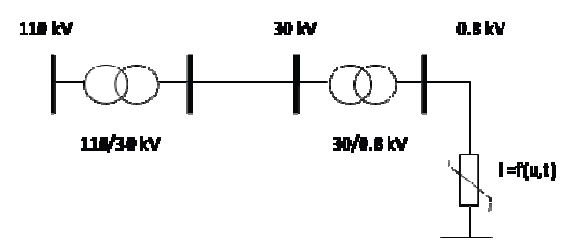
The model presented in Fig. 1 is composed of the following elements: supplying point 110kV of short-circuit power Szw= 500MVA, the main supplying point (PCC) 30kV of short circuit power Szw=200MVA, transformer 30/0.75kV, S=75MVA and nonlinear load i=f(u,t ) – arc furnace.
The parameters (RS, LS) of the model representing the supplying systems on the level 30kV have been determined using following formulas (for f=50 Hz) [3].


To ensure the continuity of arc current each electrode is controlled by independent controller. As a result the electrodes currently move depending on iron charge resistance, charge shape and phase of technology process. Currents of three-phase line are random functions. Fig. 2 shows the system with three controlled sources modelling current-voltage arc characteristics and resistances modelling the state of arc stability of each electrode. It means that system to be analyzed is nonlinear and its parameters are random [2,3,4].
To the largest and most energy consuming nonlinear high power receivers belong siderurgical arc arrangements provided with transformers amounted to power of tens MVA. The characteristic feature for the coding of charge period consists in very rough and irregular mutability of power consumption by the furnace caused by nonlinear variations of the arc resistance as well as variations of the plasma physicochemical properties in the arc’s column. The arc furnace becomes then a nonlinear asymmetric receiver, and at low level of short-circuit power it gives occasion to interferences in the power supply network, thus making worse quality of electric power supplied from the heavy current system to other consumers. Such interferences include: fluctuations and asymmetry of voltage as well as deformation of voltage curve. As the electric arc is an element of nonlinear voltage-current characteristic, therefore, the furnace draws out of the network; a considerably deformed current and becomes a source of higher currents’ harmonics. Investigation of influence of siderurgical arc arrangements on the electric power system wants establishment of higher harmonics current distribution in this system. This makes it possible to determine voltage drops of higher harmonics as well as those harmonics of voltage in any node of the system. One of the determination procedures of voltage distortion degree consists in determination of the voltage distortion factor THDV determined by the following relation [1,3]

The admissible values of voltage distortion for 30kV are [4]

The admissible values of voltage distortion for 110kV are [4]

The represented model was designed on the ground of parameters resulting from the empirical determination method of the arc voltage-current characteristic [1,3].
The furnace transformer 30/0.75 kV of power S=75 MVA has 12 degrees of voltage control. Low secondary voltage of this transformer is its characteristic feature. The most advantageous scheme of connections of a two-winding furnace transformer is:
- the primary winding with delta connection changed over voltagelesely into a star connected winding,
- the secondary winding should be always with delta connection.
Connection of the furnace transformer secondary terminals into triangle shows the following superiority in comparison with connection into star:
- the short-circuit current between electrodes is distributed into two phases of the transformer,
- connection of secondary terminals into triangle makes it possible to realize a so-called three-phase bifilar circuit.
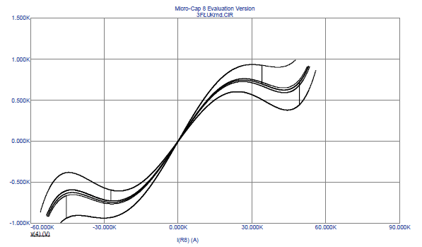
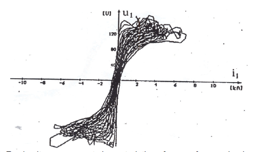
Fig. 3 presents the exemplary voltage – current characteristics of an arc in phase A. In numerical calculations we have considered the voltage-current characteristics of the real AC arc furnace. They are presented in Fig. 4.
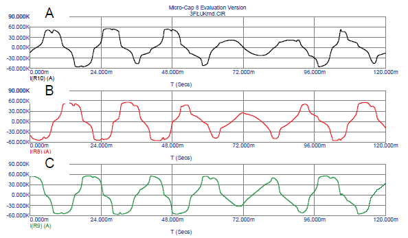
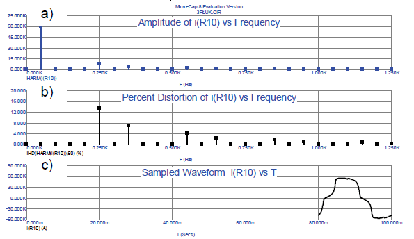

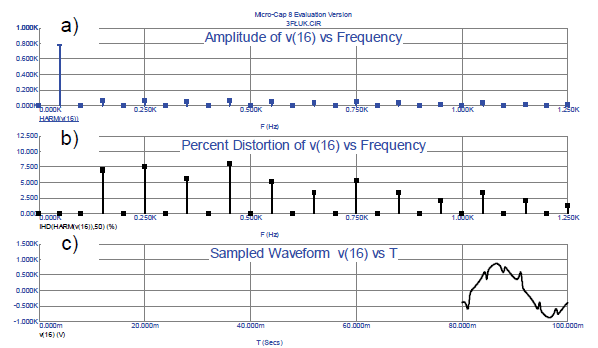
Figures 5 and 6 presents instantaneous values of currents on the primary side of transformer, the voltage on the secondary side of transformer and current of the electrodes. Figures from 7 to 10 presents the distorted currents & voltages in the system of Fig. 3. Tables 1 and 2 presents the values of currents & voltages harmonics in the circuit of Fig. 3 at nonsymmetrical load.

As a results of simulation we hale got the currents and voltages of the values very close to that in real operation of the system. After determination of the currents and voltages we can easily the other parameters of the system including the rms values of harmonics, as well THD coefficient being the basic measures of the quality of electrical energy.
Table 1. The values of the current harmonics in the circuit of Fig. 3 at nonsymmetrical load.

Table 2. The values of the voltages harmonics in the circuit of Fig. 3 at nonsymmetrical load.

Conclusions
For simulation of the changes of parameters of the electric arc we have used the random number generator built In MicroCap program.
The performed experiments allow to determine the propagation of the higher harmonics of the voltage and current generated by the nonlinear load in the power system. The model can by easily extended to the other nonlinear loads, for example the arc furnace supplied from the real system.
The comparison of the shapes of the currents in the 3 phase real system and in our model has confirmed the accuracy of the proposed approach. The results of simulation and measurements allow to assess the level of generated higher harmonics by nonlinear loads and influence of these harmonics on power system.
The modeling and simulation AC arc furnace, is a handy and recommended tool for the analysis of the power system cooperating with the nonlinear load.
This research activity was financed by the National Science Centre.
REFERENCES
[1] Brociek W., Wilanowicz R. Electric power quality parameters in transformer stations supplying nonlinear load, Przegląd Elektrotechniczny, 11/2003, pp.861 – 864.
[2] Ozgun O.Abur A.Flicker study using a novel arc furnace model, IEEE Transactions on power delivery, vol 17 no.4.10, 2002
[3] Brociek W., Wilanowicz R., Siwek K. Determination of the electric power in transformer station supplying nonlinear load: experimental and numerical study, V CPEE, Jazłowiec 2003, pp.141-144.
[4] Wang Y.F., Jiang J.G. A novel chaotic model of electric arc furnace for power quality studies, Proc.of Int. Conf. on Electrical Machines and Systems 2007, Oct. 8-11, Seoul, Korea.
Authors: dr inż. Wiesław Brociek, Warsaw University of Technology, Institute of Theory of Electrical Engineering, Measurement and Information Systems, E-mail: brociek@iem.pw.edu.pl, dr inż. Robert Wilanowicz, Radom University of Technology.
Source & Publisher Item Identifier: PRZEGLĄD ELEKTROTECHNICZNY (Electrical Review), ISSN 0033-2097, R. 87 NR 7/2011
