Published by Bogdan TUŁODZIECKI, Electric Apparatuses Factory Zwarpol Ltd. in Warsaw
Abstract. In this article were described the most frequently used constructions of high voltage test transformers. There were presented defects, advantages and application of describing constructions. There were described how to design high voltage test transformers and what is important during their design. On the basis of measurements of selected high voltage test transformers were verified correctness of computational methods. During analysis of results were presented constructors’ problems connected with a design and making a product.
Streszczenie. W artykule opisano najczęściej produkowane konstrukcje transformatorów probierczych. Podano wady, zalety i zastosowanie opisanych konstrukcji. Opisano jak należy projektować i na co należy zwrócić uwagę przy projektowaniu. Na podstawie pomiarów wybranych transformatorów probierczych zweryfikowano poprawność metod obliczeniowych. Dodatkowo analizując wyniki przedstawiono problemy z jakimi napotyka się konstruktor podczas projektowania i wykonywania wyrobu. (Transformatory probiercze, budowa, projektowanie i ich zastosowanie w układach probierczych)
Keywords: high voltage test transformers, high voltage testing systems, strength of primary isolation, withstand tests
Słowa kluczowe: transformator probierczy, układ probierczy, wytrzymałość izolacji pierwotnej, próby wytrzymałościowe
1.Introduction
High voltage test transformers are single-phase solution of transformers, which have to raise supply voltage to required value to make a dielectric withstand test of liquid or solid insulation. The strength of primary insulation, minimum value of short-circuit voltage and increasing transformer voltage ratio to level when value of secondary voltage (high voltage), reducing of voltage drop on load by power rating, it wouldn’t smaller than set value is very important in high voltage test transformers. It is essential to calculate voltage and angular errors to adequate increasing of transformer voltage ratio of high voltage test transformer and describing its voltage of short circuit. Accuracy of transformation of voltage isn’t a desirable quantity. Value of secondary voltage in high voltage testing systems is determined by rodman branch or voltage high divider, so it isn’t necessary to command of nominal transformer voltage ratio. Calculation of parameters of high voltage test transformers isn’t easy. High voltage test transformers sometimes equip with branch or branches made on secondary winding for the sake of adapting of transformer to examination of isolation with different levels of voltages and different values of power of load. In this case one kind of coil wire can’t wind secondary winding. Besides, some high voltage test transformers have two primary windings, which are link/wired in series or parallel to change its nominal transformer voltage ratio. Calculation of parameters of these high voltage test transformers is more complicated than transformers with one primary winding. High voltage test transformers are characterized by many variety of solutions on different level of complexity.
In this article the author focus his attention concentrate on High voltage test transformers made by Zwarpol Factory Ltd., where he has been working. He describe their construction, design and application in high voltage testing systems.
2.Construction
High voltage test transformers find application in high voltage testing systems to make dielectric withstand tests of specified kind of isolation, so they are subject to different criterion of selection. Because of constructional limitations of high voltage test transformers following from maximal levels of test voltages, a type of test voltages (facial or interfacial) and maximal mechanical structural strength, there aren’t produce one type high voltage test transformers.
We can make following constructions for the sake of the way of location of windings on a core:
a) when a coil or primary coils (low voltage) and a secondary coil (high voltage) are on one column of magnetic core. The secondary coil is located on a coil or primary coils. The beginning of the secondary coil and an earth electrode of core are connected and taken out from transformer to ground (Fig. 1a). This type of high voltage test transformers is the most popular, because it’s easy to define their parameters and make them.
b) when a coil or primary coils and a secondary coil are on the central column of jacket coat core. The secondary coil is located on a coil or primary coils. The beginning of the secondary coil and an earth electrode of core are connected and taken out from transformer to ground (Fig. 1b).
This solution is applied in mobile high voltage testing system, where transformer must be more mechanical resistant. This type of high voltage test transformer is marked by smaller leakage of magnetic flux than construction in point a.
c) when primary and secondary coil are split into half and located on two columns of magnetic core (Fig. 2). Coils are located in this way, that secondary coils are put on every primary coils. The beginning of the secondary coil and an earth electrode of core are taken out from transformer to ground. Primary coils are connected parallel, whereas secondary coils are connected in series. In this way we can receive half test voltage on every secondary coils. This construction is characterized by the smallest leakage of magnetic flux. Material consumption of winding is also smaller than it is in construction describing in a and b points. Unfortunately, the problem is assurance right level of primary isolation between both secondary coils, because the beginning and the end of coils, which are connected in series are located very near each other. The next problem is assurance right level of primary isolation between primary and secondary coils, because there is a half test voltage between them.
d) when is only one primary winding and many secondary windings. A primary coil is put on column of plain-frame magnetic core, while secondary coils which are connected in series are put on a primary coil. This solution in high voltage test transformer is especially applied to receive test voltage on both poles displaced about 180 (Fig. 3).
e) cascade, where binding coils are put on two columns of magnetic core. Secondary winding is put on binding coils. Primary winding or windings (law voltage) are put on a bottom secondary coil of first grade cascade. Coupling winding is put on a top secondary coil of second grade cascade in case of two or multicore cascade solution. Coupling coils are put on secondary coils in next grades of cascade. Because a core has potential of half primary voltage of every grades of cascade, so binding coils have to have the same potential as core. For this reason they are connected parallel with each other and in the same place as core. The end of bottom secondary coil and the beginning of top secondary coil are connected with each other and with core to have the same potential of core. The end of top secondary coil and the beginning of bottom secondary coil of next grade of cascade are connected with each other and connecting parallel windings (Fig. 4). High voltage test transformers with cascade construction are made when it’s impossible to make a high voltage test transformer with construction describing in point ‘a’ as regards dimensions or strength of primary isolation.
We can make following constructions for the sake of the way of making primary isolation:
a) with paper-oil primary isolation
b) with polypropylene foil and gas SF6 primary isolation
c) with resinous primary isolation
d) with silicon – estrofol foil primary isolation
e) with mix primary isolation
Selection of kind of isolation of high voltage test transformers is dependent on maximum closed-circuit voltage. The most often applied primary isolation is paper-oil isolation or polypropylene foil with gas SF6. In narrow range of test voltage is applied resinous primary isolation or silicon – estrofol foil primary isolation. The way of making of primary isolation is dependent on closed-circuit voltage at which the high voltage test transformer is made. The higher the closed-circuit voltage of transformer the more complicated execution of primary isolation.
3.Design
When we design a new High voltage test transformer we must take note of its application in high voltage testing system, which determine the main construction parameters.
Depending on use in high voltage test transformers we can distinguish following parameters:
a) rated frequency
b) primary voltage
c) secondary voltage
d) secondary voltage with short-time rating
e) short-circuit voltage
f) voltage branch measure
g) voltage branch of high voltage
h) continuous power rating
i) short-time power rating
j) primary continuous rated current
k) primary short-time rated current
For example if high voltage testing system on output should have high sinusoidal variable voltage at power-line frequency and additionally possibility to install rectifier we can design a high voltage test transformer on power-line frequency 50Hz. But if high voltage testing system on output should have rectified voltage permanently it isn’t economical solution to design high voltage test transformer on power-line frequency 50Hz. In this situation it should be design on much higher frequency than power-line frequency.
If we take the duration of the high-voltage test in a laboratory into consideration it can turn out that design of high voltage test transformer on continuous power isn’t necessary and we can design it depending on the required maximum duration of test on short-time rating.
When we define the parameters on which the high voltage test transformer have to be design we can make calculations of
a) a core and windings
b) parameters of substitute diagram
c) voltage and angle errors
Some of the most common computational schemes of high voltage test transformers are represented in Fig. 5. The values appointed by figure 1 on computational schemes are related to primary side of high voltage test transformer (law voltage), while figure 2 are related to secondary side of high voltage test transformer (high voltage)
The way of making of calculation of parameters is very similar to calculations of parameters of single-phase instrument transformers [1]; [2] so it will not be described in the article. Voltage and angle errors in case of high voltage test transformers are necessary to redimensioning transformer voltage ratio. In this situation at full active or short-time fictitious load we can get maximum value of test voltage on which the transformer was designed. At errors it was been possible to define. The value of short-circuit voltage of transformer we can also calculate on the basis of errors.
The results of calculations and measurements of parameters of three high voltage test transformers analytically designed on basis of literature [1] and [2] are following.:
a) high voltage test transformers at continuous power 2kVA, supply voltage 230V, test voltage 25kV and frequency 50Hz
b) high voltage test transformers at continuous power 1,1kVA, supply voltage 260V, test voltage 41kV and frequency 50Hz
c) high voltage test transformers at continuous power 10kVA, supply voltage 250V, test voltage 100kV and frequency 50Hz
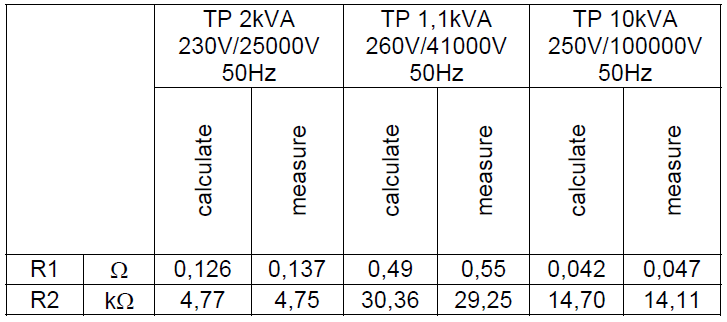
In the first stage of verification of analytic method were measured the resistances of windings of finished transformers. The results of calculate and measurement are in the Schedule 1.
Schedule 1. Windings resistance
The next steps was executed idle run and on her basis was calculated effective value current IFE and passive value current Iμ no-load current I0. The results of calculate and measurement are in the Schedule 2.
Schedule 2. Effective value IFe and passive value Iμ no-load value current I0.
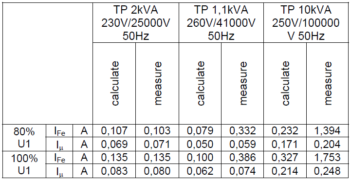
Large divergence of results for TP 1,1kVA and TP 10kVA can be connected with applied of steering screens, adjusting strengths of main isolation, which initiate additional capacity after side of winding of high voltage and also that in case of testing transformers with large voltage ratio, parallel and private windings capacity make up additional reactive load to transformer. It is hard to get idle run in case of high voltage transformers.
The next steps of verification of analytic results was been realization fault test to calculate short-circuit voltage and total reactance of both winding imported into primary side. Results for two testing transformers are in the Schedule 3.
Schedule 3. Value from fault test for two testing transformer.
4.Application
High voltage test transformers have following use:
a) in a complete high voltage testing systems to test of solid dielectric:
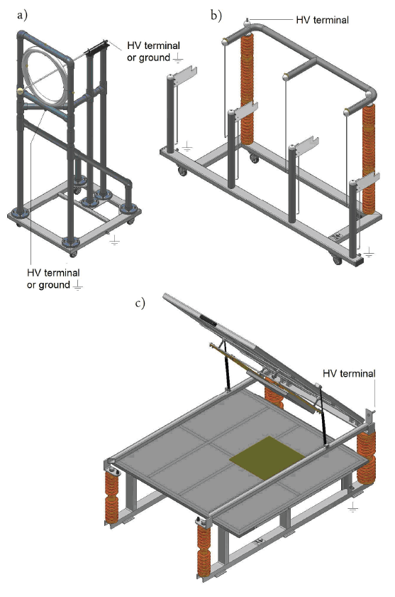
• high voltage indicator (high voltage testing systems in Fig. 7 and high voltage testing station in Fig. 6a)
• insulating stick (high voltage testing systems in Fig. 7 and high voltage testing station in Fig. 6b)
• rubber blanket (high voltage testing systems in Fig. 7 and high voltage testing station in Fig. 6c)
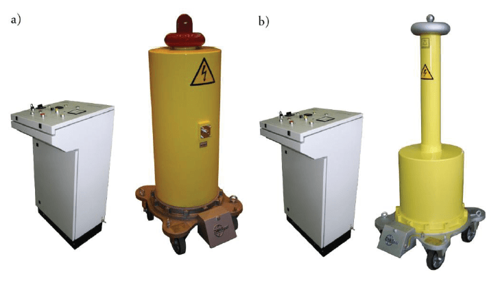
b) in high voltage testing systems to test of dielectric isolation in solid high voltage (Fig. 7b)
c) in testing device to test of dielectric isolation energetic cables by alternating or state high voltage (Fig. 8a)
d) in testing device to test of liquid dielectric isolation for example insulating oil (Fig. 8b)
e) in testing device to test dielectric isolation of dielectric gloves and dielectric shoes (Fig. 8c)

5.Conclusions
In this article were described the most frequently used constructions of high voltage test transformers. There were presented defects, advantages and limitations selected constructions of high voltage test transformers. In the article become specified parameters on which high voltage test transformer can be design with a reason of their choice. Analyzing results of prototypes of high voltage test transformers was verified correctness of computational method. Additionally comparison of results of calculations with results from measurements was used as a representation of problems which constructor encounters during design and checking of correctness of finished transformer. It is not easy to design the high voltage test transformers. Making allowance for economics factors, it is important to choose the cheapest construction of high voltage test transformer being on border of possibility of her realization. There are very important the parameters, which are characteristic for the construction because they can be essential for high voltage testing system. Knowledge of the construction of high voltage test transformers, their design and use in high voltage testing system gives the solution of the most adjustment transformer in respect of parameters and prices.
REFERENCES
[1] R. Nowicz, Voltage instrument transformers. Classic, special and unconventional Monographs of Technical University of Lodz, Lodz 2002. (in Polish)
[2] W. Starczakow, Instrument transformers, PWT, Warsaw 1959. (in Polish)
[3] E. Leśniewska, The Use of 3D Electric Field Analysis and the Analytical Approach for Improvement of a Combined Instrument Transformer Insulation System, IEEE Transactions on Magnetics, vol.38, no 2, March 2002, pp. 1233-1236
[4] E. Leśniewska, Improvement of the Electric Strength of an Insulation System of a Medium Voltage Instrument Transformer Using Field Analysis, Computer Engineering in Applied Electromagnetism, Springer 2005, Great Britain, pp.143-148
[5] Z. Flisowski, High voltage engineering, WNT, Warsaw 2009.
[6] J. Wodziński High voltage engineering of tests and measurements, PWN, Warsaw 1997
Author: mgr inż. Bogdan Tułodziecki, Fabryka aparatów elektrycznych Zwarpol Sp. z o. o. w Warszawie, ul. Żegańska 1, 04-713 Warszawa, e-mail: Bogdan.tulodziecki@zwarpol.com
Source & Publisher Item Identifier: PRZEGLĄD ELEKTROTECHNICZNY (Electrical Review), ISSN 0033-2097, R. 87 NR 1/2011
