Published by Electrotek Concepts, Inc., PQSoft Case Study: Nuisance Tripping of Sensitive Customer Power Electronic Equipment, Document ID: PQS1011, Date: October 15, 2010.
Abstract: This case study presents an investigation of nuisance tripping of sensitive customer power-electronic equipment during utility capacitor bank switching. The simulations for the analysis were completed using the PSCAD program. The power conditioning solutions included utility switches with pre-insertion resistors and customer series chokes. Both mitigation alternatives prevented the customer sensitive power- electronic equipment from tripping during the power quality events.
INTRODUCTION
A nuisance tripping of sensitive customer power-electronic equipment case study was completed for the system shown in Figure 1. The case study investigated the potential for tripping of customer power-electronic equipment during switching of a utility distribution capacitor bank. Several power conditioning mitigation alternatives, including utility switches with pre-insertion resistors and customer series reactors/chokes, were evaluated using computer simulations.

SIMULATION RESULTS
The simulations for the case study were completed using the PSCAD program. The accuracy of the simulation model was verified using three-phase and single-line-to-ground fault currents and other steady-state quantities, such as steady-state voltage rise. The circuit consisted of a 115 kV utility substation supplying a 30 MVA, 115 kV/13.2 kV step-down transformer. Three customers were also included in the simulation model to evaluate the effect of different types of power electronic loads. The customers included two 1,000 kVA, 13.2 kV/480 V step-down transformers supplying HVAC loads and one 100 kVA, 13.2 kV/415V step-down transformer supplying switch-mode power supply (SMPS) loads.
Utility capacitor bank switching is a normal system operation and the resulting transient voltages and currents are usually not a problem for utility equipment. However, there is a possibility that these low frequency transients can cause severe secondary transients if a customer has power factor capacitor banks or result in nuisance tripping of power electronic-based devices, such as adjustable-speed drives. Capacitor bank energizing is just one of the many switching events that can cause transients on a utility system. However, due to their regularity and impact on power system equipment, they quite often receive special consideration.
Power quality problems related to utility capacitor bank switching include customer equipment damage or failure, nuisance tripping of adjustable-speed drives or other process equipment, transient voltage surge suppressor failure, and computer network problems.
Energizing a shunt capacitor bank from a predominantly inductive source creates an oscillatory transient that can approach twice the normal system peak voltage (Vpk). The characteristic frequency (fs) of this transient is given by the following expression:
where:
fs = characteristic frequency (Hz)
Ls = positive sequence source inductance (H)
C = capacitance of bank (F)
fsystem = system frequency (50 or 60 Hz)
Xs = positive sequence source impedance (Ω)
Xc = capacitive reactance of bank (Ω)
MVAsc = three-phase short circuit capacity (MVA)
MVAr3φ = three-phase capacitor bank rating (MVAr)
ΔV = steady-state voltage rise (per-unit)
The characteristic energizing frequency for the simulated 7,200 kVAr, 13.2 kV distribution capacitor bank with a source strength of about 320 MVA may be approximated using the following expression:

The steady-state voltage rise for this case may be approximated using the following expression:

Relating the characteristic frequency of the capacitor bank energizing transient (fs) to a steady-state voltage rise (ΔV) design range provides a simple way of quickly determining the expected frequency range for utility capacitor bank switching. For example, a 60 Hz system with a design range of 1.0% to 2.5% would correspond to characteristic frequency range of 380 to 600 Hz. For a shunt capacitor bank on a utility bus, feeder/cable capacitance and other nearby capacitor banks cause the energizing transient to have more than one natural frequency. However, for the first order approximation, this equation can still be used to determine the dominant frequency.
Because capacitor voltage cannot change instantaneously (remembering that i(t)=Cdv/dt), energization of a capacitor bank results in an immediate drop in system voltage toward zero, followed by an oscillating transient voltage superimposed on the fundamental frequency waveform. The peak voltage magnitude depends on the instantaneous system voltage at the instant of energization and can approach twice the normal system voltage. For a practical capacitor bank energization without trapped charge, system losses, loads, and other system capacitances cause the transient magnitude to be less than the theoretical 2.0 per-unit. Typical magnitude levels range from 1.3 to 1.5 per-unit and typical transient frequencies generally fall in the range from 300 to 1000 Hz. Figure 2 illustrates an example measured distribution system capacitor bank energizing transient.
Nuisance tripping refers to the undesired shutdown of a customer’s adjustable-speed drive or other power-electronic-based process device due to a transient overvoltage on the device’s dc bus. Very often, this overvoltage is caused by utility transmission or distribution capacitor bank energization. Considering the fact that many distribution banks are time clock controlled, it is easy to see how this event can occur on a regular basis, thereby causing numerous process interruptions for customers.
An adjustable-speed drive system consists of three basic components and a control system as illustrated in Figure 3. The rectifier converts the three-phase ac input to a dc voltage, and an inverter circuit utilizes the dc signal to produce a variable magnitude, variable frequency ac voltage, that is used to control the speed of an ac motor. A dc motor drive differs from this configuration in that the rectifier is used to control the motor directly.
The nuisance-tripping event consists of an overvoltage trip due to a dc bus overvoltage on voltage-source inverter drives (e.g., pulse-width modulated inverter). Typically, for the protection of the dc capacitor and inverter components, the dc bus voltage is monitored and the drive tripped when it exceeds a preset level. This level is typically around 780 V (for 480 V applications), which is only 120% of the nominal dc voltage. The potential for nuisance tripping is primarily dependent on the switched capacitor bank rating, overvoltage controls for the switched bank, the dc bus capacitor rating, and the inductance between the two capacitors. It is important to note that nuisance tripping can occur even if the customer does not have power factor correction capacitor banks.

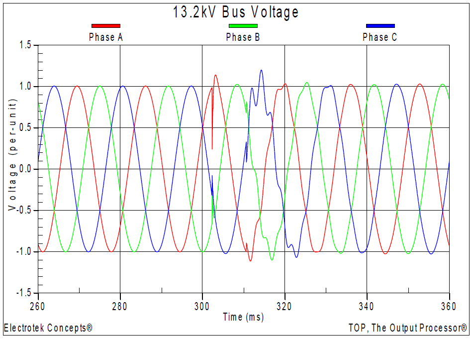
The initial simulation (Case 5a) involved the basecase condition of energizing the 7,200 kVAr, 13.2 kV distribution substation capacitor bank with no mitigation added on either the utility or customer systems. Figure 4 shows the resulting three-phase voltages at the 13.2 kV substation bus. The maximum transient overvoltage was 1.86 per-unit and the simulated steady-state voltage rise was 2.14%, which compares reasonably well with the calculated value of 2.25%.
Figure 5 shows the dc link voltages for the two customer HVAC adjustable-speed drives. The maximum dc link voltage was 912 V for the 10 hp drive with no choke and 760 V for the 15 hp drive with a 1.5% choke. The assumed trip level was 780 V. In addition, there were no utility or customer MOV arresters included in the model.


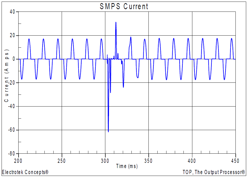
Figure 6 shows the ac current for the worst phase of the customer SMPS loads. The maximum ac current was approximately 62 A during the utility capacitor switching event. Excessive surge currents for secondary power supply loads may cause rectifier diodes, transistors, filter capacitors, MOVs, main fuses, and other components to fail.
The most effective methods for eliminating nuisance tripping are to reduce the energizing transient overvoltage, or to isolate the drives from the power system with series inductors, often referred to as chokes. The additional series inductance of the choke will reduce the transient magnitude at the input to the drive and the associated current surge into the dc link filter capacitor, thereby limiting the dc overvoltage.
A capacitor bank switch with a pre-insertion resistance provides a means for reducing the transient currents and voltages associated with the energization of a shunt capacitor bank. The impedance is shorted-out (bypassed) shortly after the initial transient dissipates, thereby causing a second transient event. The insertion transient typically lasts for less than one cycle of the system frequency. The performance of pre-insertion impedance is evaluated using both the insertion and bypass transient magnitudes, as well as the capability to dissipate the energy associated with the event, and repeat the event on a regular basis. Pre-insertion resistors and high-loss pre-insertion inductors are one of the most effective means for controlling capacitor bank energizing transients. The optimum resistor value for controlling capacitor bank energizing transients depends primarily on the capacitor bank rating and the source strength. It should be approximately equal to the surge impedance formed by the capacitor bank and source.
The second simulation (Case 5b) involved an evaluation of the utility mitigation alternative of using a capacitor bank switch equipped with a pre-insertion resistor. A standard pre – insertion resistor rating of 6.4Ω was chosen for the simulation because it was commercially available for a 15 kV class capacitor bank switch.
Figure 7 shows the resulting three-phase voltages at the 13.2 kV substation bus. The maximum transient overvoltage was reduced from 1.86 per-unit to 1.20 per-unit with the pre-insertion resistor. Figure 8 shows the dc link voltages for the two customer HVAC adjustable-speed drives for the pre-insertion case. The maximum dc link voltage was 720 V for the 10 hp drive with no choke and 644 V for the 15 hp drive with a 1.5% choke. Therefore, it was assumed that neither customer adjustable-speed drive would trip for this case. Figure 9 shows the ac current for the worst phase of the customer SMPS loads. The maximum ac current was reduced from 62 A to 30 A for the pre-insertion resistor case.
A commonly applied customer mitigation alterative is an inductive choke, which provides additional impedance in a circuit in much the same manner that an isolation transformer does, but at a much-reduced cost. They are often applied to the front-end of adjustable- speed drives to protect the drives from nuisance tripping caused by capacitor bank switching and other normal power system switching operations. Some motor drives have been found to be sensitive to overvoltages as minor as 1.2 per-unit. Inductive chokes limit these overvoltages to below the trip setting of the drive. They are generally rated as a 3% impedance, based on the drive kilowatt (or hp) rating. Some drive manufacturers now produce drives with chokes as part of their standard design. Chokes also help prevent voltage notching, caused by power electronic switching, from disturbing other equipment. They can limit notching to the drive side of the inductive choke.


The final two simulations (Case 5c and Case 5d) involved an evaluation of the customer mitigation alternative of two different choke ratings that were added to the 10 hp adjustable-speed drive. The inductance rating for a choke that is specified in %X and hp may be approximated using:
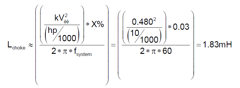
where:
fsystem = system fundamental frequency (50 or 60 Hz)
X = inductive reactance of ac choke (%)
kVφφ = system rms phase-to-phase voltage (kV)
hp = horsepower rating of the drive (hp)
Figure 10 shows the resulting simulated current waveforms highlighting the effect of adding a 3% choke to the 10 hp drive. The steady-state current distortion (ITHD) for the case with no additional choke was 77.8%. Adding a 1.5% choke reduced the current distortion to 45.9%, while adding a 3.0% choke reduced the current distortion to 36.8%. In addition, the 3% choke reduced the magnitude of the transient inrush current into the drive from approximately 344 A to 100 A.

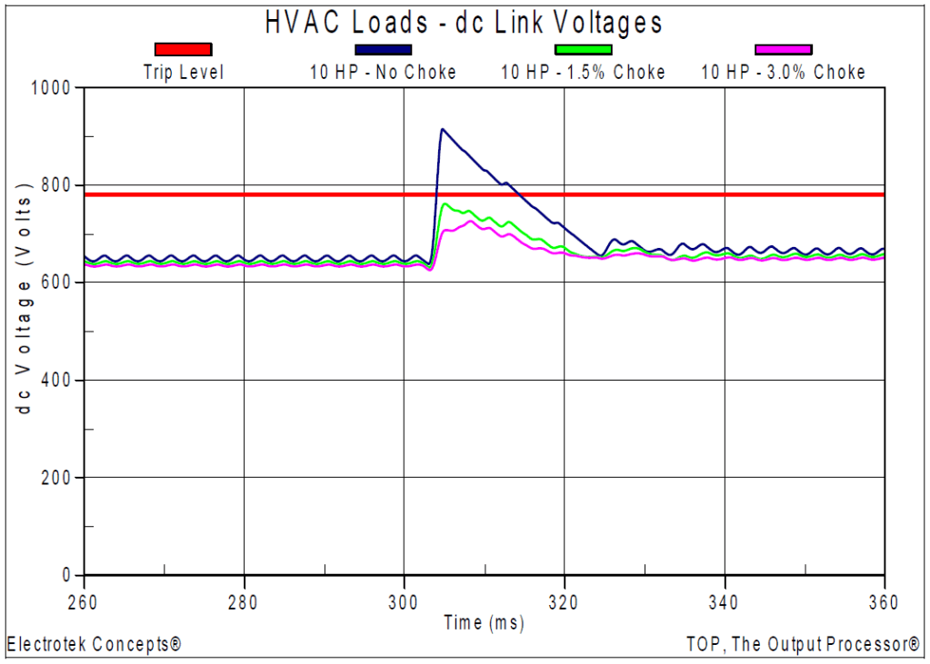
Figure 11 shows the resulting dc link voltages for the customer 10 hp adjustable-speed drive for the various simulated choke ratings (Case 5a, Case 5c, and Case 5d). The maximum dc link voltage was 912 V for the 10 hp drive with no added choke. The maximum dc link voltage was reduced from 912 V to 760 V with a 1.5% choke and to 725 V with a 3.0% choke. Since the assumed trip level was 780 V, the customer drive did not trip after the addition of the either the 1.5% or 3.0% choke.
SUMMARY
This case study investigated nuisance tripping of sensitive customer power-electronic equipment during utility capacitor bank switching. The power conditioning solutions that were evaluated included utility switches with pre-insertion resistors and customer series chokes. Both mitigation alternatives prevented the customer sensitive power-electronic equipment from tripping during the power quality events.
REFERENCES
1.IEEE Recommended Practice for Monitoring Electric Power Quality,” IEEE Std. 1159-1995, IEEE, October 1995, ISBN: 1-55937-549-3.
2.IEEE Recommended Practice for Emergency & Standby Power Systems for Industrial & Commercial Applications (IEEE Orange Book, Std. 446-1995), IEEE, ISBN: 1559375981.
3.R.C. Dugan, M.F. McGranaghan, S. Santoso, H.W. Beaty, “Electrical Power Systems Quality,” McGraw-Hill Companies, Inc., November 2002, ISBN 0-07-138622-X.
RELATED STANDARDS
IEEE Std. 1159, IEEE Std. 1100, IEEE Std. 446, ANSI Std. C84.1
GLOSSARY AND ACRONYMS
ASD: Adjustable-Speed Drive
CF: Crest Factor
DPF: Displacement Power Factor
PF: Power Factor
PWM: Pulse Width Modulation
THD: Total Harmonic Distortion
TPF: True Power Factor
