Published by Electrotek Concepts, Inc., PQSoft Case Study: General Reference – Utility Capacitor Switching, Document ID: PQS0302, Date: January 10, 2003.
Abstract: The application of utility capacitor banks has long been accepted as a necessary step in the efficient design of utility power systems. Also, capacitor switching is generally considered a normal operation for a utility system and the transients associated with these operations are generally not a problem for utility equipment. These low frequency transients, however, can be magnified in a customer facility (if the customer has low voltage power factor correction capacitors) or result in nuisance tripping of power electronic based devices, such as adjustable-speed drives.
Capacitor energizing is just one of the many switching events that can cause transients on a utility system. However, due to their regularity and impact on power system equipment, they quite often receive special consideration.
INTRODUCTION
The application of utility capacitor banks has long been accepted as a necessary step in the efficient design of utility power systems. Also, capacitor switching is generally considered a normal operation for a utility system and the transients associated with these operations are generally not a problem for utility equipment. These low frequency transients, however, can be magnified in a customer facility (if the customer has low voltage power factor correction capacitors) or result in nuisance tripping of power electronic based devices, such as adjustable-speed drives (ASDs). Capacitor energizing is just one of the many switching events that can cause transients on a utility system. However, due to their regularity and impact on power system equipment, they quite often receive special consideration.
Transient overvoltages and overcurrents related to capacitor switching are classified by peak magnitude, frequency, and duration. These parameters are useful indices for evaluating potential impacts of these transients on power system equipment. The absolute peak voltage, which is dependent on the transient magnitude and the point on the fundamental frequency voltage waveform at which the event occurs, is important for dielectric breakdown evaluation. Some equipment and types of insulation, however, may also be sensitive to rates of change in voltage or current. The transient frequency, combined with the peak magnitude, can be used to estimate the rate of change.
There are a number of transient related concerns that are generally evaluated when transmission and distribution shunt capacitor banks are applied to the power system. These concerns include insulation withstand levels, switchgear ratings and capabilities, energy duties of protective devices, and system harmonic considerations. In addition, these considerations need to be extended to include customer facilities due to the increased use of power electronic based end-user equipment. Applications concerns often evaluated include:
− overvoltages associated with normal capacitor energization.
− open line/cable end transient overvoltages.
− phase-to-phase transients at transformer terminations.
− voltage magnification at lower voltage capacitor banks (including customer systems).
− arrester duties during restrike events.
− current-limiting reactor requirements.
− system frequency response and harmonic injection.
− impact on sensitive customer power electronic loads.
− ferroresonance and dynamic overvoltage conditions.
Power quality symptoms related to utility capacitor switching include customer equipment damage or failure, nuisance tripping of ASDs or other process equipment, transient voltage surge suppressors (TVSS) failure, and computer network problems.
CAPACITOR BANK ENERGIZATION
Transient characteristics are dependent on the combination of the initiating mechanism and the electric circuit characteristics at the source of the transient. Circuit inductances and capacitances – either discrete components such as shunt capacitance of power factor correction banks or inductances in transformer windings, or stray inductance or capacitance because of proximity to other current carrying conductors or voltages – are responsible for the oscillatory nature of transients. Natural frequencies within the power system depend on the system voltage level, line lengths, cable lengths, system short circuit capacity, and the application of shunt capacitors.
Characteristics of Energizing an Isolated Capacitor Bank
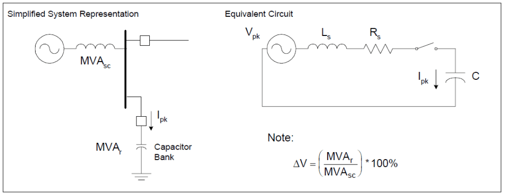
Energizing a shunt capacitor bank from a predominantly inductive source results in an oscillatory transient that can approach twice the normal system peak voltage (Vpk). Figure 1 illustrates the simplified equivalent system for the energizing transient. The characteristic frequency (fs) of this transient is given by:

and the peak inrush current (Ipk) is determined using:

where:
[example]
fs = characteristic frequency (Hz) = [379 Hz]
Ls = positive sequence source inductance (H) = [17.53mH]
C = capacitance of bank (F) = [10.03μF]
fsystem = system frequency (50 or 60 Hz) = [60 Hz]
Xs = positive sequence source impedance (Ω) = [6.61 Ω]
Xc = capacitive reactance of bank (Ω) = [264.50 Ω]
MVAsc = three-phase short circuit capacity (MVA) = [2000 MVA]
MVAr = three-phase capacitor bank rating (MVAr) = [50 MVAr]
ΔV = steady-state voltage rise (per-unit) = [2.5%]
Vpk = peak line-to-ground bus voltage (V) = [93897.11 V]
Zs = surge impedance (Ω) = [39.35 Ω]
Relating the characteristic frequency of the capacitor energizing transient (fs) to a steady-state voltage rise (ΔV) design range provides a simple way of quickly determining the expected frequency range for utility capacitor switching. For example, a 60 Hz system with a design range of 1.0% to 2.5% would correspond to characteristic frequency range of 380 to 600 Hz. For a shunt capacitor bank on a high voltage bus, transmission line capacitance and other nearby capacitor banks cause the energizing transient to have more than one natural frequency. However, for the first order approximation, the equation above [1] can still be used to determine the dominant frequency.
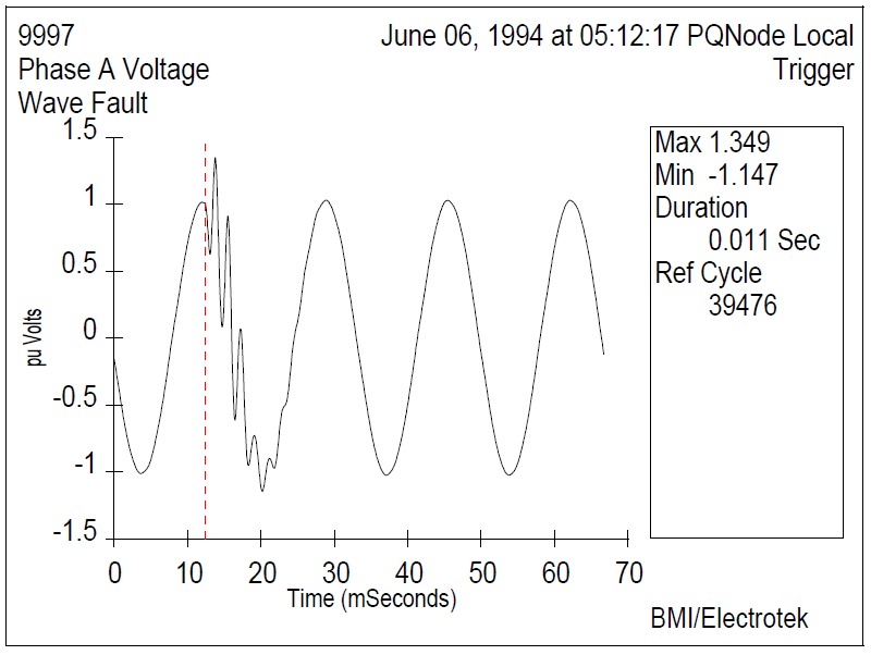
Because capacitor voltage cannot change instantaneously (remembering that i(t)=Cdv/dt), energization of a capacitor bank results in an immediate drop in system voltage toward zero, followed by an oscillating transient voltage superimposed on the 60 Hz fundamental waveform. The peak voltage magnitude depends on the instantaneous system voltage at the instant of energization, and can reach 2.0 times the normal system voltage (Vpk – in per-unit) under worst-case conditions. The voltage surge is at the same frequency as the inrush current (Ipk) and rapidly decays to the system voltage.
For a practical capacitor energization without trapped charge, system losses, loads, and other system capacitances cause the transient magnitude to be less than the theoretical 2.0 per-unit. Typical magnitude levels range from 1.2 to 1.8 per-unit and typical transient frequencies generally fall in the range from 300 to 1000 Hz. Figure 2 illustrates an example (measured) distribution system capacitor energizing transient.
Energizing an ungrounded-wye capacitor bank can result in slightly higher transient overvoltages because of unequal pole closing. In general, the transient overvoltages associated with normal closing are similar to those for grounded banks.
Characteristics of Energizing Back-to-Back Capacitor Banks
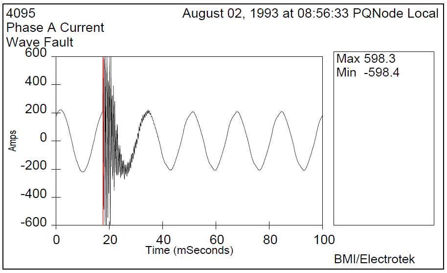
Energizing a shunt capacitor bank with an adjacent capacitor bank already in service is known as “back-to-back” switching. High magnitude and frequency currents, illustrated in Figure 3, will flow between the banks when the second bank is energized. This current must be limited to acceptable levels for switching devices and current transformer burdens. Generally, series reactors are used with each bank to limit the current magnitude and frequency, although pre-insertion resistors/inductors may be used with some types of switches.
The frequency and magnitude of the inrush current during back-to-back switching depends upon the size of the discharging capacitor bank, the impedance of the discharging loop, and the instantaneous capacitor bank terminal voltage at the time of contact closure. The impedance of the discharging loop is determined by the inductance between the banks rather than the system inductance (Ls). The magnitude of the inrush current is therefore much higher than for the isolated bank energization (Ipk). Typically, the inrush current lasts for only a fraction a power frequency cycle.
This high-frequency inrush current may exceed the transient frequency momentary capability of the switching device (e.g. ANSI C37.06-1987) as well as the I2t withstand of the capacitor fuses. It may also cause false operation of protective relays and excessive voltages for current transformers (CTs) in the neutral or phase of grounded-wye capacitor banks. The current must be evaluated with respect to the transient frequency momentary capability (close and latch) rating of the switch, as well as the I2t withstand of the capacitor fuses. Switch manufacturers should be consulted for the appropriate current (Ipk) and frequency (f) ratings of the device. High frequency substation ground mat currents may be controlled by connecting the two neutral points together and grounding with a single connection to the grid.
Solutions to excessive inrush currents usually involves:
− adding current-limiting reactors to decrease the peak current and frequency of the oscillatory inrush current.
− adding pre-insertion resistors or inductors to the switching device.
− adding synchronous closing control to the switching device.
− selecting component ratings (e.g. breaker, CT burdens, etc.) to withstand the inrush current characteristics.
OVERVOLTAGE MITIGATION
Devices for capacitor switching transient control either attempt to minimize the overvoltage (or overcurrent) at the point of application, or limit (clip) the overvoltage at local and remote locations. These devices include:
− a) synchronous closing control (also known as zero voltage closing)
− b) pre-insertion devices (resistors and/or inductors)
− c) fixed inductors
− d) MOV arresters
Previous research has suggested that the effectiveness of these control methods is system dependent, and that detailed analysis is required to select the optimum control scheme. While often justifiable for large transmission applications, transient analysis of distribution capacitor applications is rarely performed, and in general, banks are installed without transient overvoltage control. Each of these methods has various advantages and disadvantages in terms of transient overvoltage reduction, cost, installation requirements, operating/maintenance requirements, and reliability.
Timing Control
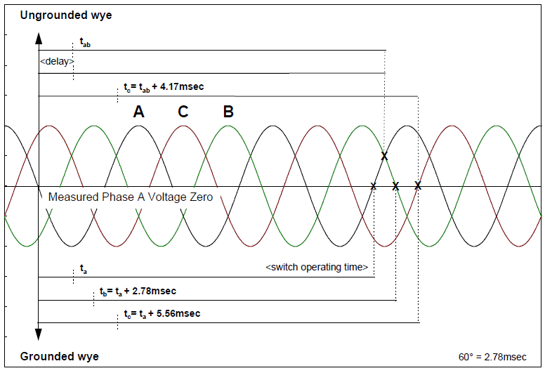
Synchronous closing is independent contact closing of each phase near a voltage zero, as illustrated in Figure 4. To accomplish closing at or near a voltage zero (avoiding high prestrike voltages), it is necessary to apply a switching device that maintains a dielectric strength sufficient to withstand system voltages until its contacts touch. Although this level of precision is difficult to achieve, closing consistency of ±0.5 milliseconds should be possible. Previous research has indicated that a closing consistency of ±1.0 millisecond provides overvoltage control comparable to properly sized pre-insertion resistors. The success of a synchronous closing scheme is often determined by the ability to repeat the process under various (system and climate) conditions. Adaptive, microprocessor-based control schemes that have the ability to “learn” from previous events address this concern. The primary benefits of this capability are the control’s ability to compensate for environmental factors and the increased reliability (less maintenance) that can be achieved
Grounded capacitor banks are controlled by closing the three phases at three successive phase-to-ground voltage zeros (60° separation). Ungrounded banks are controlled by closing the first two phases at a phase-to-phase voltage zero and then delaying the third phase 90 degrees (phase-to-ground zero).
Pre-insertion Devices
A pre-insertion impedance (resistor or inductor) provides a means for reducing the transient currents and voltages associated with the energization of a shunt capacitor bank. The impedance is “shorted-out” (bypassed) shortly after the initial transient dissipates, thereby producing a second transient event. The insertion transient typically lasts for less than one cycle of the system frequency. The performance of pre-insertion impedance is evaluated using both the insertion and bypass transient magnitudes, as well as the capability to dissipate the energy associated with the event, and repeat the event on a regular basis. The optimum resistor value for controlling capacitor energizing transients depends primarily on the capacitor size and the source strength.
Fixed Inductors
Fixed inductors have been used successfully to limit inrush currents during back-to-back switching. Typically the value of these inductors is on the order of several hundred microhenries. In addition, inductors provided for outrush (into a nearby fault) current control may be applied, and are typically 0.5 – 2.0 millihenries. Previous research indicates that these fixed reactors do not provide any appreciable transient overvoltage reduction.
MOV Arresters
Metal oxide varistors (MOVs) can limit the transient voltages to the arrester’s protective level (maximum switching surge protective level, typically 1.8 – 2.5 per-unit) at the point of application. The primary concern associated with MOV application is the energy duty during a restrike event. Although a rare occurrence, a switch restrike generally results in the highest arrester duty for arresters located at the switched capacitor. In addition, remote arresters (including low voltage customer applications) may be subjected to severe energy duties if voltage magnification occurs. This condition could be especially troublesome for distribution systems if SiC arresters remain in service.
POWER QUALITY CONSIDERATIONS
Voltage Magnification:
Voltage magnification occurs when a transient oscillation, initiated by the energization of a utility (transmission or distribution) capacitor bank, excites a series resonance formed by a lower voltage system. The result is a higher overvoltage at the lower voltage bus. Previous analysis has indicated that the worst magnified transient occurs when the following conditions are met (refer to Figure 5):
− The size of the switched capacitor bank is significantly larger (>10) than the lower voltage (often customer power factor correction) bank (i.e. 50MVAr versus 1.8MVAr ≈ 28).
− The energizing frequency (fs) is close to the series resonant frequency formed by the step-down transformer and the power factor correction capacitor bank (f2) (i.e. 465Hz @ 230kV bus vs. 440Hz @ 13.2kV bus).
− There is relatively little damping (resistive) provided by the low voltage load (typical industrial plant configuration – primarily motor load).
Distribution system overvoltages, resulting from transmission capacitor bank energization, may be sufficient to spark-over SiC arresters. MOV arresters should be capable of withstanding the event, however this should verified using computer simulations and/or TNA analysis. Low voltage customer systems may be exposed to transient overvoltages (illustrated in Figure 6) between 2.0 and 4.0 per-unit, (previously determined by computer simulations and in-plant measurements) and these overvoltages may occur over a wide range of low voltage capacitor sizes (note that the low voltage capacitor must exist for magnification to occur). Typically, the transient overvoltages will simply damage low-energy protective devices (MOVs) or cause a nuisance trip of a power electronic-based device. However, there have been several cases when complete failure of customer equipment (single process device) has occurred.
Important system variables to consider when analyzing this phenomenon include:
− Switched capacitor bank size
− Lower voltage capacitor bank size and location
− System loading
− Transformer characteristics
− Circuit breaker characteristics (closing resistors/inductors, closing control, etc.).
− Arrester size(s), rating(s), and location(s)

A number of utilities and their customers have evaluated and tested several possible solutions to the voltage magnification problem, including:
− Detuning the circuit by changing capacitor bank sizes, moving banks, and/or removing banks from service (utility and/or customer).
− Switching large banks in more than one section.
− Using one of the presently available overvoltage control methods, such as:
• pre-insertion resistors or inductors
• synchronous closing control
− Applying surge arresters (MOVs) at the remote location(s).
− Detuning the circuit by converting low voltage power factor correction banks into harmonic filters.
Each of these methods has been utilized in the field with varying degrees of success. Typically, the optimum approach considers the economics of the solution in conjunction with the engineering analysis. Quite often the economic evaluation is incomplete due to the fact that it may be very difficult to determine the cost of a particular power quality event for an individual customer. A cooperative approach between utility and customer(s) will generally lead to a mutually agreeable, cost-effective engineering solution.
Nuisance Tripping of ASDs
Nuisance tripping refers to the undesired shutdown of an ASD (or other power-electronic-based process device) due to the transient overvoltage on the device’s dc bus. Very often, this overvoltage is caused by transmission and/or distribution capacitor bank energization. Considering the fact that many distribution banks are time clock controlled, it is easy to see how this event can occur on a regular basis, thereby causing numerous process interruptions for the customer.
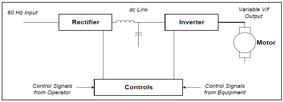
An ASD system consists of three basic components and a control system as previously illustrated in Figure 7. The rectifier converts the three-phase ac input to a dc voltage, and an inverter circuit utilizes the dc signal to produce a variable magnitude, variable frequency ac voltage, that is used to control the speed of an ac motor. A dc motor drive differs from this configuration in that the rectifier is used to control the motor directly.
The nuisance tripping event consists of an overvoltage trip due to a dc bus overvoltage on voltage-source inverter drives (i.e. pulse-width modulated – PWM). Typically, for the protection of the dc capacitor and inverter components, the dc bus voltage is monitored and the drive tripped when it exceeds a preset level. This level is typically around 780 volts (for 480 V applications), which is only 120% of the nominal dc voltage. The potential for nuisance tripping is primarily dependent on the switched capacitor bank size, overvoltage controls for the switched bank, the dc bus capacitor size, and the inductance between the two capacitors. It is important to note that nuisance tripping can occur even if the customer does not have power factor correction capacitors.
The most effective methods for eliminating nuisance tripping are to significantly reduce the energizing transient overvoltage, or to “isolate” the drives from the power system through the use of series inductors, often referred to as “chokes”. The additional series inductance of the choke will reduce the transient magnitude at the input to the ASD and the associated current surge into the dc link filter capacitor, thereby limiting the dc overvoltage.
While determining the precise inductor size for a particular application may require a fairly detailed computer simulation study, a more common approach involves the wide-spread application of a standard “3%” value. The 3% size is based upon the drive kVA rating and is usually sufficient for most applications where voltage magnification isn’t also a concern. Figure 8 illustrates an example (simulation) dc overvoltage transient before and after the application of a 3% ac choke.

Note: The reader is warned that should the application of a choke in the 3-5% range not solve the nuisance tripping problem, the customer should not arbitrarily increase the size (i.e. 10%) in hopes of eventually solving the problem. It is likely that the drive would fail to function properly. The utility and drive manufacturer should be contacted.
SUMMARY
There are many events that can cause a power quality problem. Analysis of these events is often difficult due to the fact that the cause of the event may be related to a switching operation within the facility or to a power system fault hundreds of miles away. This document summarizes several of the more common power quality problems associated with the application of utility system capacitor banks. The frequent switching of utility capacitor banks coupled with the increasing application of sensitive customer equipment has led to a heightened awareness of several important events, including voltage magnification and nuisance tripping of ASDs.
These concerns have become particularly important as utilities institute higher power factor penalties, thereby encouraging customers to install power factor correction capacitors. In addition, nontraditional customer loads, such as ASDs, are being applied in increasing numbers due to the improved efficiencies and flexibility that can be achieved. This type of load can be very sensitive to the transient voltages produced during capacitor switching.
REFERENCES
G. Hensley, T. Singh, M. Samotyj, M. McGranaghan, and T. Grebe, Impact of Utility Switched Capacitors on Customer Systems Part II – Adjustable Speed Drive Concerns, IEEE Transactions PWRD, pp. 1623-1628, October, 1991.
G. Hensley, T. Singh, M. Samotyj, M. McGranaghan, and R. Zavadil, Impact of Utility Switched Capacitors on Customer Systems – Magnification at Low Voltage Capacitors, IEEE Transactions PWRD, pp. 862-868, April, 1992.
T.E. Grebe, Application of Distribution System Capacitor Banks and Their Impact on Power Quality, 1995 Rural Electric Power Conference, Nashville, Tennessee, April 30-May 2, 1995.
M. McGranaghan, W.E. Reid, S. Law, and D. Gresham, Overvoltage Protection of Shunt Capacitor Banks Using MOV Arresters, IEEE Transactions PAS, Vol. 104, No. 8, pp. 2326-2336, August, 1984.
S. Mikhail and M. McGranaghan, Evaluation of Switching Concerns Associated with 345 kV Shunt Capacitor Applications, IEEE Transactions PAS, Vol. 106, No. 4, pp. 221-230, April, 1986.
T.E. Grebe, Technologies for Transient Voltage Control During Switching of Transmission and Distribution Capacitor Banks, 1995 International Conference on Power Systems Transients, September 3-7, 1995, Lisbon, Portugal.
Electrotek Concepts, Inc., An Assessment of Distribution System Power Quality – Volume 2: Statistical Summary Report, Final Report, EPRI TR-106294-V2, EPRI RP 3098-01, May 1996.
Electrotek Concepts, Inc., Evaluation of Distribution Capacitor Switching Concerns, Final Report, EPRI TR-107332, October 1997.
RELATED STANDARDS
IEEE Standard 18-1992, IEEE Standard 1036-1992
ANSI/IEEE Standard C37.012-1979, ANS/IEEE C37.99-1990
GLOSSARY AND ACRONYMS
AS: Adjustable-Speed Drive
PWM: Pulse Width Modulation
MOV: Metal Oxide Varistor
TVSS: Transient Voltage Surge Suppressors
