Published by Electrotek Concepts, Inc., PQSoft Case Study: General Reference – Using Simulations and Measurements in PQ Analysis, Document ID: PQS0309, Date: April 16, 2003.
Abstract: Simulations provide a convenient means to characterize power quality problems, predict disturbance characteristics, and evaluate possible solutions to problems. They should be performed in conjunction with monitoring efforts and measurements for verification of models and identification of important power quality concerns. The models required for the simulations depend on the system characteristics and the power quality variations being evaluated.
The specific power quality concerns that need to be evaluated will be different for each customer. A review of the electrical configuration, protection practices, types of equipment used by the customer, process requirements, and economic impacts of problems will lead to a list of concerns that need to be studied.
USING SIMULATIONS AND MEASUREMENTS IN POWER QUALITY ANALYSIS
Power quality concerns that need to be evaluated will be different for each utility and customer configuration. A review of the electrical configuration, protection practices, types of equipment used by the customer, process requirements, and economic impacts of problems will lead to a list of concerns that need to be studied. These concerns can include possible problems with both the utility system and customer facilities. Possible power quality problem categories include:
- Voltage transients caused by circuit switching and load switching within the customer facility.
- Harmonic distortion from the application of adjustable-speed drives or other nonlinear loads.
- Transformer heating caused by harmonic current levels.
- Transient voltage magnification at low voltage capacitor banks.
- Sensitivity of adjustable-speed drives (ASDs) and control systems to utility capacitor switching transients.
- Transients and notching associated with power electronic equipment operation.
- Neutral conductor overloading due to harmonic producing loads in commercial installations.
- Voltage flicker from arc furnace loads and arc welding loads.
- Voltage sags due to faults on parallel circuits on the same distribution system or faults on the transmission system.
- Momentary interruptions at industrial and commercial installations due to recloser operations on feeder circuit breakers.
- Coupled voltages in customer facilities due to lightning transients on the primary distribution systems.
Identification of the particular concerns involved for an installation provides a focus for a simulation-based study. Development of a model for analysis of the problem is dependent on the frequency range of the power quality variations that need to be studied. The model can be for computer simulations, hand calculations, or application of simple rules. For example, analysis of voltage sags often requires modeling that includes the utility transmission system, while analysis of high frequency transients might only require a model for a very local part of the customer facility.
Monitoring requirements are also based on the particular concern involved. If harmonic distortion is a concern, monitoring of steady-state conditions with a harmonic analyzer is required. Analysis of disturbances requires a disturbance monitor. The duration of monitoring depends on how often the problems occur. Some problems with voltage sags or momentary interruptions might only occur a few times per year due to faults on the transmission system, while problems caused by capacitor switching might occur every day. Other voltage variations of interest will typically fall somewhere between these extremes.
Data Collection Process
A representation of the customer system and important parts of the utility system should be developed for preliminary analysis. This model can be used for preliminary simulations or analysis to predict power quality problems and evaluate possible solutions to problems. In cooperation with the customer, the data for the model is collected and compiled into a database for convenient reference during the study.
Important information includes:
1. Utility system characteristics:
− Primary voltage
− Short circuit / load levels
− Feeder configuration and characteristics – underground/overhead
− Transformer ratings / connections / impedances
− Protection practices, switching procedures
− Capacitor applications (locations, sizes, switching method and controls)
− Arrester sizing and placement
2.Customer load characteristics:
− Motors
− Power electronics / process controls
− Computers / lighting
− Adjustable-speed drives
− Transformer ratings / connections / impedances
− Conductor lengths, impedance characteristic
− Customer capacitor sizes, locations, switching procedures
− Customer equipment and circuit switching
3.Power conditioning equipment:
− Surge suppressors (arresters, varistors, etc.)
− Isolation transformers
− Constant voltage transformers
− Voltage regulators / power conditioners
− UPS systems
− Harmonic filters
− Custom power devices (utility distribution system)
Computer Simulation Process
Simulations provide a convenient means to characterize power quality problems, predict disturbance characteristics, and evaluate possible solutions to problems. They should be performed in conjunction with monitoring efforts and measurements for verification of models and identification of important power quality concerns. The models required for the simulations depend on the system characteristics and the power quality variations being evaluated. The simulations fall into three major categories:
− Transient simulations are often performed using the Electromagnetic Transients Program (EMTP). There are a number of different versions and platforms available. This is a valuable tool for analysis of circuit switching operations, capacitor switching, lightning transients, and transients associated with power electronic equipment operation.
The most widely used program for transient analysis is the EMTP. This program is used to simulate electromagnetic, electromechanical, and control system transients in multiphase power systems. It was originally developed by Hermann Dommel at Bonneville Power Administration (BPA) during the late 1960’s. Since then, there have been significant developments by groups all over the world.
The EMTP is a general-purpose computer program for simulating high-speed transient effects on electric power systems. The program features an extremely wide variety of modeling capabilities encompassing electromagnetic and electromechanical oscillations ranging in duration from microseconds to seconds. Examples of its use include switching and lightning surge analysis, insulation coordination, shaft torsional oscillations, ferroresonance, and HVDC converter control and operations.
The EMTP is used to solve the ordinary differential and/or algebraic equations associated with an “arbitrary” interconnection of different electrical and control system components. The implicit trapezoidal-rule (second order) integration is used on the describing equations of most elements that are modeled by ordinary differential equations. The result is a set of real, simultaneous, algebraic equations, which is solved at each time-step. These equations are written in nodal-admittance form, and are solved by ordered triangular factorization.
Studies involving use of the EMTP have objectives that fall in two general categories. One is design, which includes insulation coordination, equipment ratings, protective device specification, control systems design, etc. The other is solving operating problems such as unexplained outages or equipment failures.
Currently, primary development and support for member utilities is coordinated by EPRI and the Development Coordination Group (DCG). Additional DCG/EPRI EMTP information may be obtained from: http://www.emtp96.com/.
Another version of the EMTP is the Alternative Transients Program (ATP). The ATP is the royalty-free version of the EMTP. ATP is distributed by the ATP User’s Group for your country. ATP licensing is free, and requires only that you agree to the licensing terms. Additional ATP information may be obtained from: http://www.ee.mtu.edu/atp/ and
− Harmonic investigations are typically performed using steady-state analysis techniques at the individual harmonic frequencies. In general, harmonic-producing loads can be modeled as harmonic current sources, and the simulations used to predict harmonic voltages and currents throughout the customer and utility systems. Overloading of neutral conductors, transformer heating considerations, resonances caused by capacitor applications, and harmonic currents injected onto the utility system can be evaluated in the simulations.
SuperHarm, a harmonic simulation program developed by Electrotek Concepts, Inc. as part of the EPRI HarmFlo+ Workstation, uses a steady-state frequency domain analysis. The solution technique is a direct admittance matrix solution. This method requires that the system admittance matrix be solved for each harmonic of interest. A nonlinear device is modeled as a shunt-connected constant current source. The magnitude and angle of current injected at each harmonic frequency is determined with a Fourier transformer of the device’s line current waveform. SuperHarm allows the user to input harmonic current sources without concern for the phase angle between the bus voltage and the fundamental current.
Most harmonic simulation programs in use throughout the world use the admittance matrix approach similar to the one utilized in SuperHarm. Examples include V-HARM (Cooper Power Systems), CYMHARMO (Cyme) and HARMZW (CEPEL).
− Variations in the fundamental frequency voltage can be evaluated with conventional steady-state analysis tools. Power flow programs give system voltages as a function of load levels on the system. Fault programs (short circuit analysis) can calculate system voltage profiles during fault conditions for analysis of voltage sag concerns.
Computer programs used to solve power flows are divided into two types – static and dynamic (real time). Most power flow studies for system analysis are based on static network conditions. Real time power flows are primarily used for optimization of generation, VAr control, dispatch, losses, and tie line control.
A power flow solution gives the voltages at all buses and the power flow in all branches for a given set of operating conditions. It represents a steady state in which the influential parameters are in balance and a solution has been found. A power flow study is a collection of such solutions made when certain equipment parameters are set at different values.
Power flow/stability program vendors include EPRI, PTI (PSS/U), BPA/WSCC, Power Computing Associates, General Electric, Philadelphia Electric, ABB, and CYME.
There are numerous short circuit programs that can be used for power quality investigations. The full list given above for power flow/stability programs also provides short circuit programs. An addition to the list is ASPEN OneLiner. This program includes a special feature that allows convenient evaluation of voltage sag area of vulnerability.
In general, a process of developing a simple system model and working towards a more complete (and often more complex) model for an overall analysis yields the best results. A simplified system model allows the user to develop an understanding of the phenomena of interest. In addition, data verification is more efficient using this method. Once an understanding has been developed and the initial model has been verified, the user can then expand the system model to include more components. The overall study is then performed and solutions to the particular problem may be developed and analyzed.
Monitoring Process
The utility and customer systems being evaluated should be monitored to characterize the power quality variations and to verify the analytical models developed for simulations. The measurement program should be designed based on initial simulation results and on the particular sensitive loads existing at the customer facility. Monitoring will typically be performed on the feeder, at the customer service entrance, and close to the sensitive load. This will permit characterization of disturbances originating on the utility system and disturbances that are localized at the load. A measurement program plan should be developed which specifies:
− quantities to monitor
− monitoring durations
− threshold levels which will trigger recording of disturbances
− waveform sampling and data storage requirements
− analysis procedures and data presentation formats
Available monitoring instruments should be evaluated for the measurements required. The problem of obtaining adequate representation of both harmonic and transient conditions must be addressed in particular, if both of these concerns exist at a facility.
A customer site survey should be part of the measurement program design. The site survey should characterize the wiring and distribution system integrity and provide basic information about circuit and equipment loading. The site survey should also include discussions with facility personnel regarding characteristics of equipment problems and known customer system conditions at the time power quality variations have occurred.
The actual monitoring effort requires close cooperation between the customer and utility personnel. Monitoring sites and instrumentation should be selected based on the particular concerns being characterized. The duration of monitoring effort will depend on the parameters that can affect the power quality concerns. It is likely that the customer will need to be responsible for verifying that the monitor is operating properly on a day-to-day basis. The monitoring results should be compiled and analyzed for verification of analytical models and to provide a concise description of the possible concerns.
Selecting the Appropriate Monitoring Equipment
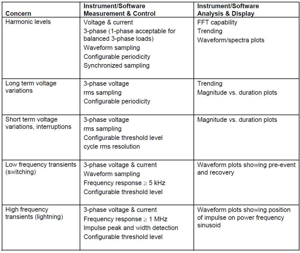
Power quality problems encompass a wide range of disturbances and conditions on the system. They include everything from very fast transient overvoltages (microsecond time frame) to long duration outages (hours or days time frame). Power quality problems also include steady-state phenomena such as harmonic distortion, and intermittent phenomena, such as voltage flicker. This wide variety of conditions that make up “power quality” makes the development of standard measurement procedures and equipment very difficult. Table 1 indicates the equipment requirements for identifying and monitoring specific power quality problems.
Table 1 – Equipment Requirements
Instrument Types
Although instruments have been developed that measure a wide variety of disturbances, a number of different instruments are generally necessary, depending on the phenomena being investigated. Basic categories of instruments that may be applicable include:
− Wiring and Grounding Test Devices
− Multimeters
− Oscilloscopes
− Disturbance Analyzers
− Harmonic Analyzers/Spectrum Analyzers
− Flicker Meters
Transducer Requirements
Monitoring of power quality on power systems often requires transducers to obtain acceptable voltage and current signal levels. Voltage monitoring on secondary systems can usually be performed with direct connections but even these locations require current transformers (CTs) for the current signal.
Many power quality monitoring instruments are designed for input voltages up to 600Vrms and current inputs up to 5Arms. Voltage and current transducers must be selected to provide these signal levels. There are two important concerns that must be addressed in selecting transducers:
− Signal levels. Signal levels should use the full scale of the instrument without distorting or clipping the desired signal.
− Frequency response. This is particularly important for transient and harmonic distortion monitoring, where high frequency signals are particularly important.
EVALUATING RESULTS
The measurement results are analyzed in conjunction with the results of simulations to correlate customer problems with the utility system power quality levels. The initial measurements and the site survey are used to identify the phenomena involved and the important parameters. The subsequent measurement results are used to verify the model and characterize the actual power quality variations. Using this information, the model can then be used for more detailed simulations of possible solutions to the power quality problem. The simulations provide the means to evaluate a range of possible solutions from a technical point of view.
Once the range of technical solutions is identified, economic analyses need to be performed to evaluate the possible alternatives for solving customer power quality problems. These alternatives will generally include the following options:
− Power conditioning and/or filtering at the sensitive loads
− Central power conditioning and/or filtering at the customer service entrance
− Changing operating procedures or system design on the utility distribution system
− Modification to the design of sensitive loads to make them less sensitive to power quality variations
The requirements for each of these options will be developed from the simulation effort and the analysis of measurement results.
Power conditioning in this case includes surge suppression, voltage regulation, and possibly backup for momentary interruptions. Harmonic filtering to solve harmonic problems can be applied either at individual loads or at the main service for a facility. Customer system design modifications, such as changing power factor correction procedures and equipment, can have an important impact on power quality variations. If particular loads are much more sensitive that other loads in the facility, either power conditioning at the particular load or design changes to the load equipment should be considered.
Momentary interruptions and voltage sags require careful consideration. Utility system modifications could include implementation of switching procedures to minimize transients associated with capacitor switching events or addition of current limiting devices to minimize the voltage sags that occur during faults on parallel feeders. The impact of protection practices on power quality levels experienced by customers should be evaluated carefully using both the analytical and measurement results.
SUMMARY
Simulations provide a convenient means to characterize power quality problems, predict disturbance characteristics, and evaluate possible solutions to problems. They should be performed in conjunction with monitoring efforts and measurements for verification of models and identification of important power quality concerns. The models required for the simulations depend on the system characteristics and the power quality variations being evaluated.
The specific power quality concerns that need to be evaluated will be different for each customer. A review of the electrical configuration, protection practices, types of equipment used by the customer, process requirements, and economic impacts of problems will lead to a list of concerns that need to be studied.
REFERENCES
Potential Transformer Accuracy at 60 Hz Voltages Above and Below Rating and at Frequencies Above Hz, D. A. Douglass, presented at the IEEE Power Engineering Society Summer Meeting, Minneapolis, MN, July 13-18, 1980.
Current Transformer Accuracy with Asymmetric and High Frequency Fault Currents, D. A. Douglass, IEEE Transactions on Power Apparatus on Systems, Vol. PAS-100 No. 3, March, 1981.
Transducer Performances for Power System Harmonic Measurements, C. J. Cokkinides, L. E. Banta, A. P. Meliopoulos, Proceedings of the International Conference on Harmonics, Worcester, MA, October 1984.
Computation of Current Transformer Transient Performance, IEEE Transactions on Power Delivery, Vol. PWRD-3 No. 4, October 1988.
Electrical Transients in Power Systems, Second Edition, Chapter. 18, A. N. Greenwood, John Wiley and Sons, New York, 1991.
RELATED STANDARDS
IEEE Standard 1159
IEEE Standard 1346
IEEE Standard 1250
IEEE Standard 1036
IEEE Standard 519
GLOSSARY AND ACRONYMS
ASD: Adjustable-Speed Drive
CT: Current Transformer
EMTP: Electromagnetic Transients Program
HVAC: High-Voltage Air Conditioning
MOV: Metal Oxide Varistor
PF: Power Factor
PWM: Pulse Width Modulation
TVSS: Transient Voltage Surge Suppressors
