Published by Electrotek Concepts, Inc., PQSoft Case Study: General Reference – Ferroresonance, Document ID: PQS0607, Date: July 1, 2006.
Abstract: The term ferroresonance refers to a special kind of resonance that involves capacitor and iron-core inductance. The most common condition in which it causes disturbances is when the magnetizing impedance of a transformer is placed in series with a system capacitor. There are several modes of ferroresonance with varying physical and electrical characteristics. Some have very high voltages and currents, while others have voltages close to normal. There may or may not be equipment failures or other evidence of ferroresonance in the electrical equipment. In many cases it may be may be difficult to tell if ferroresonance has occurred, unless there are witnesses or power quality monitoring instruments installed.
This case presents an overview of ferroresonance and a number of example measured and simulated waveforms.
OVERVIEW OF FERRORESONANCE
Ferroresonance is a term generally applied to a wide variety of interactions between capacitors and iron-core inductors that result in unusual voltage and/or currents. In linear circuits, resonance occurs when the capacitive reactance equals the inductive reactance at the frequency at which the circuit is excited. Iron-core inductors have a nonlinear characteristic and therefore a range of inductance values. This relationship may lead to a number of operating conditions where the inductive reactance does not equal the capacitive reactance, but very high and damaging overvoltages occur.
In a typical power system, ferroresonance occurs when a transformer becomes isolated on a cable section in such a manner that the cable capacitance appears to be in series with the magnetizing characteristic of the transformer. An unbalanced switching operation is required to initiate the condition.
Several of the more common causes include:
- single-phase cutouts
- fuse blowing or opening (transformer or line fuse) (or a lineman pulls an elbow connector)
- single-phase reclosers
- cable connector of splice opening
- manual cable switching to reconfigure a cable circuit during an emergency condition
- open conductor fault in overhead line feeding cable
- three-phase switch with large pole closing span
Two additional conditions must be satisfied for ferroresonance to occur:
- The length of cable between the transformer and open conductor location must have sufficient capacitance to produce excessive ferroresonant voltages
- The losses in the circuit and the resistive load on the transformer must be low.
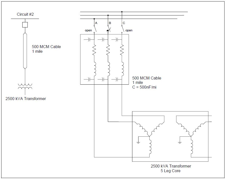
These conditions may be met at a variety of times. The low resistive load requirement is often satisfied on new construction projects, when there may be no load on the transformer for a period of time. As the load increases, ferroresonance becomes much less likely (unless the customer separates from the utility during emergency conditions). Figure 1 illustrates one possible switching condition that can lead to ferroresonance. The case, which was investigated using computer simulations, involves a stuck-pole in the feeder switch. A number of different scenarios may lead to this condition, however, for the purposes of simulation, it is simply modeled as two phases open and one closed.
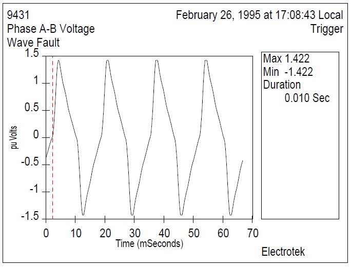
There are several modes of ferroresonance with varying physical and electrical characteristics. Some have very high voltages and currents, while others have voltages close to normal, as illustrated in Figure 2. There may or may not be equipment failures of other evidence of ferroresonance in the electrical equipment. In many cases it may be may be difficult to tell if ferroresonance has occurred, unless there are witnesses or power quality monitoring instruments installed.
One thing common to all types of ferroresonance is that the steel core is driven into saturation, often deeply and randomly (otherwise, it is conventional resonance). As the core goes into a high flux density, it will make an audible noise due to the magnetostriction of the steel and movement of the core laminations. The sound produced is distinctly different and louder than the normal hum of a transformer. Another reported symptom of the high magnetic field is charring or bubbling of the paint on the top of the transformer tank. This is due to stray flux heating in parts of the transformer where magnetic flux is not expected. Since the core is saturated repeatedly, the magnetic flux will find its way into the tank wall and other metallic parts.
If high voltages accompany the ferroresonance, there could be electrical damage to both the primary and secondary circuits. Surge arresters commonly fail during this condition. Arrester failures are related to the heating of the arrester block, and at times, the failures can be catastrophic, with parts being expelled from the arrester housing.
Ferroresonance cannot always be entirely avoided; however, steps can be taken to reduce the probability of occurrence. These include locating fuses or disconnects near the transformer (to minimize capacitance), and using three-phase switches. However, neither of these remedies will provide protection for the broken conductor case. Another common solution involves using grounded-wye / grounded-wye transformers. When each phase is magnetically independent, this connection prevents ferroresonance. However, the common five-legged core design of three-phase padmount transformers is still susceptible to ferroresonance because the phases are magnetically coupled.
FERRORESONANCE WAVEFORM EXAMPLES
Figure 3 illustrates an example distribution voltage during a ferroresonance event. Phases A-B and C-A are shown. These waveforms were recorded with a Dranetz-BMI 8010 PQNode.

Figure 4 shows an example simulated distribution system ferroresonance event. This voltage waveform was produced using the Electromagnetic Transients Program (EMTP).
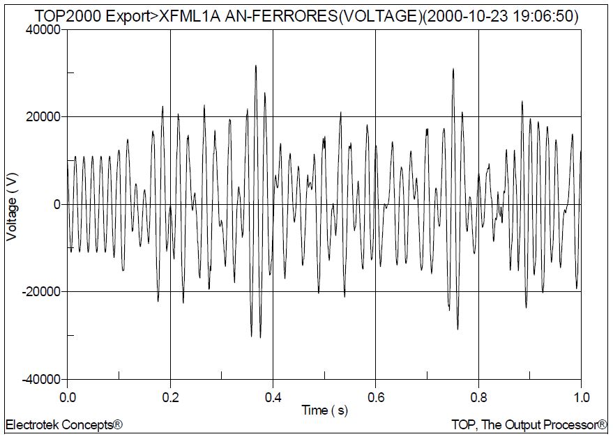
Figure 5 shows an example simulated distribution system ferroresonance event. This voltage waveform was produced using the FerroView program.
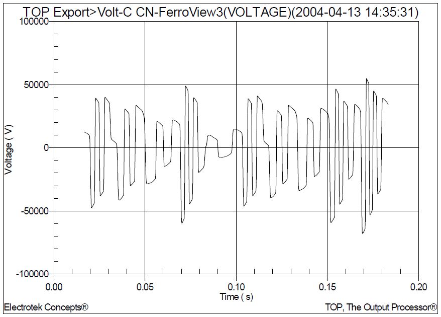
Figure 6 shows an example simulated distribution system ferroresonance event. This voltage waveform was produced using the PSCAD program.

Figure 7 shows an example simulated distribution system ferroresonance event. A resistive load is added to the circuit at 0.3 seconds. This voltage waveform was produced using the PSCAD program
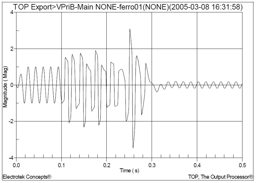
Figure 8 shows an example distribution system voltage during a ferroresonance event. These voltage waveforms were recorded with a Dranetz-BMI 8010 PQNode.
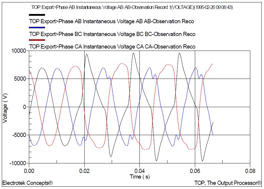
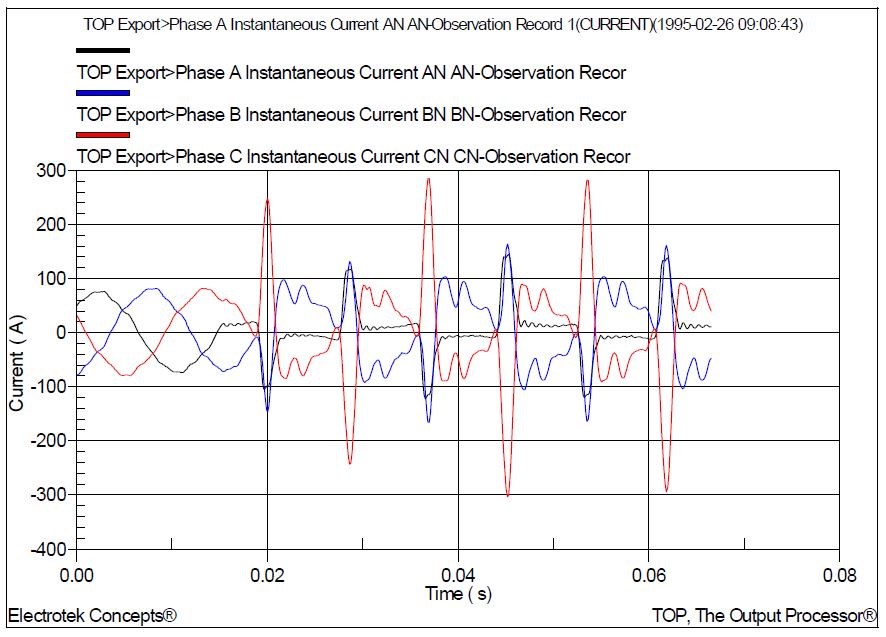
Figure 9 shows an example distribution system feeder current during a ferroresonance event. These current waveforms were recorded with a Dranetz-BMI 8010 PQNode.
SUMMARY
Ferroresonance is a term generally applied to a wide variety of interactions between capacitors and iron-core inductors that result in unusual voltage and/or currents. These interactions may lead to a number of operating conditions where high and damaging overvoltages occur. Ferroresonance is different than resonance in linear system elements. In linear systems, resonance results in high sinusoidal voltages and currents of the resonant frequency. Ferroresonance can also result in high voltages and currents, but the resulting waveforms are usually irregular and chaotic in shape, as illustrated with the example waveforms in the case study.
REFERENCES
Tennessee Valley Public Power Association, Inc., Power Quality Manual, Final Report, Project PQ 2, 2002.
RELATED STANDARDS
IEEE Std. C57.105-1978
GLOSSARY AND ACRONYMS
MOV: Metal Oxide Varistor Arrester
MSSPL: Maximum Switching Surge Protective Level
SiC: Silicon Carbide Arrester
