Published by Electrotek Concepts, Inc., PQSoft Case Study: Customer Induction Motor Starting Evaluation, Document ID: PQS0904, Date: October 15, 2009.
Abstract: This case study shows the results for simulations completed to determine the severity of an undervoltage condition during starting of a customer induction motor starting. The simulations for the case were completed using the PSCAD program. The effectiveness of a primary resistor starter is also summarized.
INTRODUCTION
A customer induction motor starting evaluation was completed for the system shown in Figure 1. The simulations for the case study were completed using the PSCAD program. The case involved simulating an undervoltage condition during starting of a 500 hp motor on a 480-volt customer bus. An example of a representative measured voltage waveform is shown in Figure 2. The accuracy of the simulation model was verified using three-phase and single-line-to-ground fault currents and other steady-state quantities, such as motor full load current. The circuit modeled for the case involved a 230kV system supplying a 34.5kV distribution feeder that supplies a 1,500 kVA customer step-down transformer (34.5kV/480V).


Motor starting is one of the most common causes of voltage variations. An induction motor will draw several times its full load current during starting. This lagging current creates a voltage drop across the impedances of the system. If the started motor is large enough relative to the system short-circuit capacity, these voltage drops can produce severe voltage sags on the system. Even small and medium horsepower motors can have inrush currents that are six-to-ten times the normal steady-state current levels. Motor starting voltage sags can dim lights, cause contactors to drop out, and disrupt sensitive customer equipment. These voltage sags may also affect the motor starting itself, because severe voltage sags may prevent the motor from successfully starting. Motor starting voltage sags may persist for many seconds.
Relevant system and induction motor data for the case included:
| Three-phase induction motor rating: | 500 hp |
| Rated induction motor voltage: | 480 V |
| Motor efficiency: | 92.0% |
| Motor full load power factor: | 90.0% |
| Motor full load slip: | 2.0% |
| Motor full load current: | 542 A |
| Motor three-phase rating: | 450 kVA |
| Motor starting current (5.7 x IFL): | 3089 A |
| Motor locked rotor kVA: | 2565 kVA |
| Short-circuit current at motor terminal: | 28 kA |
| Short-circuit kVA at motor terminal: | 23280 kVA |
SIMULATION RESULTS
For a full voltage start, the voltage drop in per-unit of nominal system voltage may be estimated using the following expression:

where:
V(pu) = actual system voltage (per-unit)
kVASC = system short-circuit kVA at motor (kVA)
kVALR = motor locked rotor kVA (kVA)
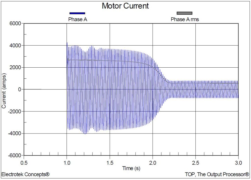
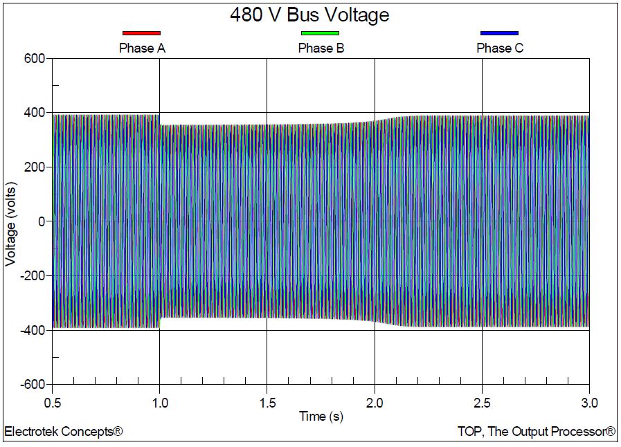
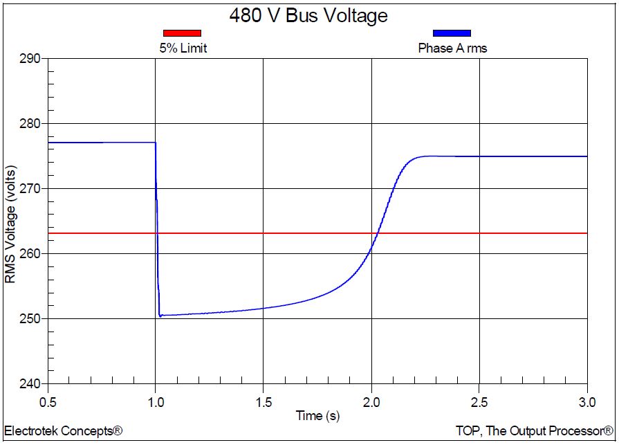
On a 480-volt bus, this rms phase-to-neutral voltage drop would be 249.6 volts. This full voltage starting condition was simulated in the first case. The phase A current is shown in Figure 3. The figure also includes the calculated rms current. The rms voltage and current quantities were determined using digital rms meters in the simulation program. The maximum simulated peak current for the full voltage start was 4275 A and the full load rms current was 565 A. The three-phase 480-volt bus voltage during full voltage motor starting is shown in Figure 4. The rms voltage is shown in Figure 5. The minimum rms voltage for the case was 250.3 volts, which is very close to the hand-calculated value of 249.6 volts.
Assuming that the maximum allowable voltage drop is 5%, the simulated 10% voltage drop for the full voltage starting case indicates that some type of mitigation is required. There are several motor starting techniques to limit the motor starting current including autotransformer starters, resistance and reactance starters, delta-wye starters, and shunt capacitor starters.
The second case investigated the effectiveness of a primary resistor motor starter to achieve the 5% voltage limitation. A primary resistor starter has one or more sets of resistors which are connected in series with the motor during starting. The resistors are typically bypassed by a contactor once the motor has reached full speed. Figure 6 shows the motor current for the case with a primary starting resistor. As can be observed from the figure, the magnitude of the starting current is lower than the full voltage case; however the motor takes somewhat longer to reach full speed.
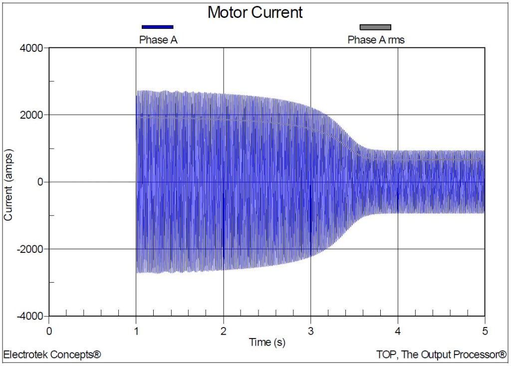
Figure 7 shows the simulated rms voltage for both the full voltage and primary resistor starter cases. The primary resistor starter reduces the magnitude of the voltage drop so that is very near the assumed 5% limit.

SUMMARY AND CONCLUSIONS
This case study shows the results for simulations completed to determine the severity of an undervoltage condition during starting of a customer induction motor starting. The effectiveness of a primary resistor starter is also summarized.
REFERENCES
- IEEE Std. 1159-1995, IEEE Recommended Practice on Monitoring Electrical Power Quality, ISBN 1-5593-7549-3.
- IEEE Std. 1159.3-2003, IEEE Recommended Practice for the Transfer of Power Quality Data, ISBN 0-7381-3578-X.
- TOP, The Output Processor®, Electrotek Concepts, Inc., http://www.pqsoft.com/top/
RELATED STANDARDS
IEEE Std. 1159.3, IEEE Std. 1159
GLOSSARY AND ACRONYMS
ASD: Adjustable Speed Drive
UPS: Uninterruptible Power Supply
PSCAD: Power Systems Computer Aided Design
