Published by Electrotek Concepts, Inc., PQSoft Case Study: Harmonic Issues Related to Power Factor Correction, Document ID: PQS0604, Date: April 1, 2006.
Abstract: Power factor correction is an important facet of power quality. Capacitors may be installed on customer systems to minimize charges for poor power factor on their electric bill. These installations may create problems by altering the harmonic frequency response of the network or introducing transient disturbances during their energization. This case study presents an overview of the impact of power factor correction on harmonics issues, such as resonance.
INTRODUCTION
Electric utilities and their customers have long been concerned with power quality. The need for constant voltage and frequency has always been recognized. However, recent trends toward energy conservation, the increasing utilization of power electronic loads, and the proliferation of sensitive electronic equipment are changing the definition of what is meant by “constant voltage.” The primary reasons for the growing concern include:
− Load equipment is more sensitive to power quality variations than equipment applied in the past. Many new load devices contain microprocessor-based controls and power electronic devices that are sensitive to many types of disturbances.
− The increasing emphasis on overall power system efficiency has resulted in a continued growth in the application of devices such as high-efficiency adjustable-speed motor drives and shunt capacitors for power factor correction to reduce losses. This is resulting in increasing harmonic levels on power systems and has many people concerned about the future impact on system capabilities.
− Increased awareness of power quality issues by the end users. Utility customers are becoming better informed about such issues as interruptions, sags, and switching transients and are challenging the utilities to improve the quality of power delivered.
− Many things are now interconnected in a network. Integrated processes mean that the failure of any component has much more important consequences.
HARMONIC RELATED ISSUES
Harmonics can cause equipment to misoperate, capacitor banks to fail, breakers to trip mysteriously, but in general, the electric power system has the ability to absorb substantial amounts of harmonic current with surprisingly little or no impact on connected equipment. Real problems from harmonics are usually confined to locations with high amounts of nonlinear, harmonic current-producing loads or power factor correction capacitors. Examples of this include a wastewater treatment plant where the entire load may be comprised of adjustable-speed motor drives powering pumps, or situations where power factor correction capacitors on the customer system or at the utility distribution level create resonances that amplify the effects of nonlinear loads.
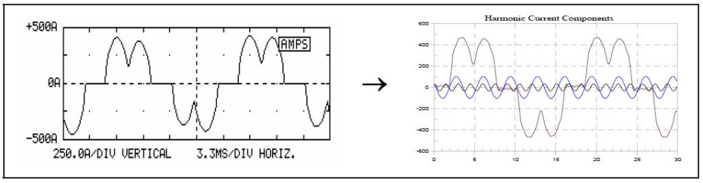
Figure 1 shows how a distorted harmonic waveform can be represented by a series of sine waves. In the figure, only the fundamental frequency, the fifth harmonic and the eleventh harmonic sine waves are shown along with the resultant waveform. This resultant is starting to look like the distorted wave at the left. If all the frequency components are added in, the resultant will be the same as the waveform at the left.
Almost all harmonic distortion problems occur when a resonant frequency exists near the 5th or 7th harmonics (11th or 13th harmonics can also be a problem if a large percentage of the load is nonlinear). Simple calculations can be used to estimate the system resonant frequencies. Existence of resonances near characteristic harmonic frequencies of loads that have been identified as harmonic sources is an early indication of potential trouble.
Distorted currents, and the distorted voltages they create as they flow through system impedances, can reduce equipment operating reliability and service life. Potential problems include the following:
− Failure of power factor correction capacitors. The presence of power factor correction capacitors in a facility greatly increases the potential for harmonic problems. A capacitor can cause the system to resonate near a harmonic frequency resulting in high voltage and/or current distortion that can destroy the capacitor or cause nuisance capacitor fuse/breaker operations.
− Equipment misoperation. Circuit breakers, adjustable-speed drives, programmable logic controllers, and other equipment employ control circuits that may not operate correctly in a distorted environment. Distortion of the equipment supply voltage may cause inaccurate measurement of control input signals. It can produce multiple zero crossings per cycle of the input signal waveform, causing crossing detectors to malfunction. Typical problems include clocks running fast, hunting and oscillation in motor speed control systems, and circuit breaker failure to trip or nuisance trips.
− Overheating of transformers. Transformer core losses and other stray losses vary roughly with the square of the frequency of the load current. Therefore, harmonic load currents significantly increase transformer heating. This problem is most severe in dry-type transformers.
− Overloading of neutral conductors in three-phase four-wire circuits serving single-phase electronic power supply loads. As with transformers, harmonic currents increase conductor heating. However, the neutral conductor is of special concern due to the triplen harmonic currents from each phase adding in the neutral. Though balancing loads among the phases will eliminate fundamental current in the neutral, this is not true for the triplens (triplen harmonics are odd multiples of the third harmonic, e.g., 3, 9, 15, 21…). Neutral current can be approximately 70% higher than phase conductor current for circuits serving balanced computer loads.
Harmonic Resonance
The application of nonlinear loads results in harmonic currents flowing on the power system. The interaction of these currents with the system impedance determines the voltage distortion levels throughout the system. This case study presents important concepts for determining the system frequency response characteristics. Simple systems can be analyzed with hand calculations or spreadsheets. Systems that are more complicated require computer programs that can solve for the system characteristics at multiple frequencies.
Harmonic voltage distortion is a result of the voltage drop created across the equivalent power system impedance by harmonic currents from nonlinear loads. Once the characteristics of the harmonic sources have been identified, the response of the power system at each harmonic frequency must be developed to determine the impact of the nonlinear load on harmonic voltage distortion.
At any point within a power system, the equivalent impedance at fundamental frequency can be determined from short-circuit current information. At the fundamental frequency (60 Hz), power systems are primarily inductive, and the equivalent impedance is sometimes called the short-circuit reactance. The equivalent inductance may be determined using:
where:
kVφφ = system rms phase-to-phase voltage (kV)
MVA3φ = three-phase short circuit capacity (MVA)
XSC = system short circuit reactance (Ω)
LSC = system short circuit inductance (H)
ω = system frequency (rad/sec = 2*π*fsystem)
At harmonic frequencies, the impedance of the equivalent inductance may be determined using:
where:
XSCh = system reactance at harmonic h (Ω)
LSC = system short circuit inductance (H)
fh = power system fundamental frequency (Hz)
h = harmonic number
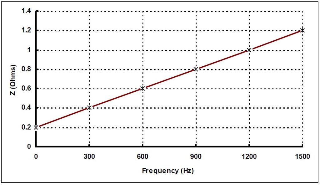
A graph of impedance versus frequency for this simple system representation would look similar to Figure 2. Real power systems are not as linear. As frequency increases, the effect of elements not included in the 60 Hz short circuit calculation, such as line and transformer capacitance and load, becomes more significant. At the lower-order harmonic frequencies, however, useful calculations can still be performed with this simple representation. With an estimate of the harmonic spectrum for the nonlinear load current, the impedance characteristic can be used to estimate the impact of the load on the voltage distortion at the point of connection.
At utilization voltages, the equivalent system reactance is usually dominated by local impedance. A good approximation for Xsc may be based on the impedance of the local step-down transformer (Xtx):
Xsc ≈ Xtx
While not precise (ignores the system impedance on the high side of the transformer), this relationship is usually sufficient to evaluate whether or not significant harmonic distortion can be expected. Transformer impedance (Ztx(%) – nameplate impedance in percent at rating) may be approximated using:
where:
kVφφ = system rms phase-to-phase voltage (kV)
MVA3φ = three-phase transformer rating (MVA)
XSC = system short circuit reactance (Ω)
Xtx = transformer reactance (Ω)
For example, for a 1500 kVA, 6% impedance transformer, the equivalent impedance on the low side (480 volt) may be approximated using:
Impact of Capacitors – Parallel Resonance
Shunt capacitors in the power system dramatically alter the system impedance variation with frequency. Capacitors are one of the most linear elements of the power system and do not create harmonics themselves. However, severe harmonic distortion can sometimes be attributed to their presence. While the reactance of inductive components increases proportionately to frequency, capacitive reactance, XC, decreases proportionately:
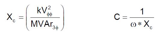
where:
XC = capacitor bank reactance (Ω)
C = capacitor bank capacitance (F)
kVφφ = system rms phase-to-phase voltage (kV)
MVAr3φ = three-phase capacitor bank rating (MVAr)
ω = system frequency (rad/sec = 2*π*fsystem)
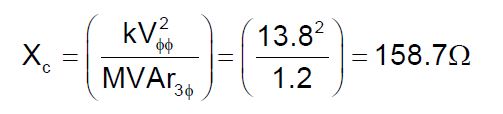
For example, the capacitive reactance for a 1200 kVAr, 13.8 kV capacitor bank may be determining using:
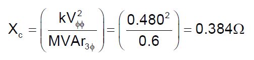
and the reactance for a 600 kVAr, 480 volt capacitor bank may be determined using:
At harmonic frequencies, shunt capacitors appear to nonlinear loads as being in parallel with the equivalent system inductance. At the frequency where XC and XSC are equal, the parallel impedance (combination of inductance and capacitance), as seen by the nonlinear load, becomes very high. This frequency (fr) is known as the resonant frequency for that particular circuit configuration, and it may be determined using:
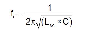
where:
fr = parallel resonant frequency (Hz)
LSC = system short circuit inductance (H)
C = capacitor bank capacitance (F)
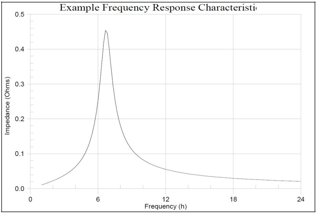
An example illustration of system impedance as a function of frequency (see Figure 3) clearly shows the effect of the capacitor bank.
Because the inductance and capacitance are connected in parallel, this condition is known as parallel resonance. Other, perhaps more convenient, forms of this equation include:
where:
hr = parallel resonant frequency (x fundamental)
XC = capacitor bank reactance (Ω)
XSC = system short circuit reactance (Ω)
MVA3φ = three-phase short circuit capacity (MVA)
MVAr3φ = three-phase capacitor bank rating (MVAr)
kVAtx = three-phase transformer rating (kVA)
kVAr3φ = three-phase capacitor bank rating (kVAr)
Ztx% = transformer reactance (%)
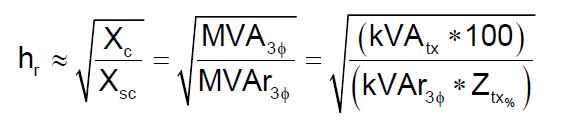
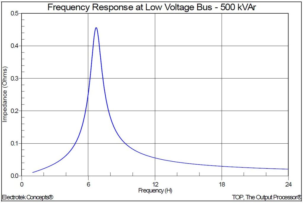
For example, the resonant frequency for a 1500 kVA, 6% impedance transformer and a 500 kVAr capacitor bank may be approximated using:
where:
hr = resonant frequency (x fundamental)
Xc = capacitor reactance
Xsc = system short circuit reactance
MVAsc = system short circuit MVA (200)
MVArcap = MVAr rating of capacitor bank (0.500)
kVAtx = kVA rating of step-down transformer (1500)
Ztx = step-down transformer impedance in percent (6)
kVArcap = kVAr rating of capacitor bank (500)
A more accurate calculation would include the source impedance (200 MVA):
Xsc = Xtx + Xs
where:

Therefore, for this example, including the source impedance reduced the estimated harmonic resonance from 7.07 to 6.67. The simulation result for this case is shown in Figure 4. The impact of the source impedance will be dependent on the source strength (available fault current, also referred to as a stiff or weak system) and the size and impedance of the customer’s step-down transformer. Generally, ignoring the source impedance for an approximation of the resonant frequency is a reasonable assumption.
The high impedance at the parallel resonant frequency may result in high voltage harmonic magnitudes (and magnified current harmonic magnitudes in the resonant circuit) if the resonance corresponds to one of the harmonic components associated with the nonlinear load. It is usually a problem if the parallel resonance is close to one of the lower order characteristic harmonics (e.g., 5th or 7th harmonic). Problems have also occurred with higher frequency resonances (e.g., 11th, 13th) but they are less common.
Impact of Capacitors – Series Resonance
Another possible system/capacitor interaction, known as series resonance, may also be a concern. The series combination of an inductor and a capacitor appears as a very small (theoretically zero) impedance at its resonant frequency. There are certain instances where a shunt capacitor and the inductance of a transformer or distribution line may appear as a series LC circuit to a source of harmonic currents. If the resonant frequency corresponds to a characteristic harmonic frequency of the nonlinear load, the LC circuit will attract a large portion of the harmonic current that is generated. For example, a customer not having any nonlinear load, but utilizing power factor correction capacitors, may in this way experience high harmonic voltage distortion due to neighboring harmonic sources.
The series resonance circuit is used to an advantage when designing harmonic filters. In this case, the series resonance is designed to occur near a characteristic harmonic of the nonlinear loads and the elements of the filter are specified to withstand the required level of harmonic current and voltage.
As indicated in the simulated frequency response characteristic, shown in Figure 5, for the series resonant circuit, a parallel resonance is also introduced at a value below the harmonic frequency of the series resonance (see previous example for a 1500 kVA, 6% impedance transformer and a 500 kVAr, 4.7th filter). The harmonic number for the new parallel resonance may be approximated using:
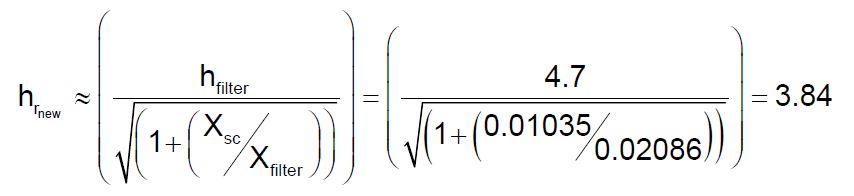
where:
hrnew = resulting (new) parallel resonant frequency (x fundamental)
XSC = system short circuit reactance (Ω)
Xfilter = reactance of series filter reactor (Ω)
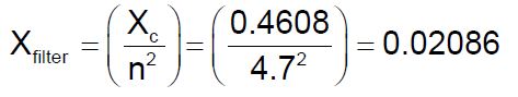

This frequency should be checked when designing filters to make sure that the parallel resonance is not introduced at a lower order characteristic harmonic. For example, installing a 7th harmonic filter may retune the system to the 5th harmonic and increase the voltage distortion level. It is generally good practice to apply filters starting at the lowest characteristic harmonic to avoid this problem.
Benefit of Applying Power Factor Correction Capacitors as Harmonic Filters
When mitigation of harmonic distortion is required, one of the options is to apply a filter at the source of harmonics, or at a location where the harmonic currents can be effectively removed from the system. The most cost effective filter is generally a single-tuned passive filter and this will be applicable for the majority of cases. Filters must be carefully designed to avoid unexpected interactions with the system.
The need for filters is often precipitated by an adverse system response due to the addition of power factor correction capacitors, resulting in resonance. These adverse system responses to harmonics can be modified by changing the capacitance or the reactance. Two methods that require the addition of intentional reactance are:
− Adding a shunt filter. Not only does this shunt troublesome harmonic currents off the system, but also it completely changes the system response, often, but not always, for the better. This is the most common type of filtering applied because of economics and that it tends to smooth the load voltage as well as remove the current.
− Adding a reactor to the system to simply tune the system away from resonances. Harmful resonances are generally between the system inductance and shunt power factor correction capacitors. The reactor must be added between the capacitor and the power source. One method is to simply put a reactor in series with the capacitor to move the system resonance without actually tuning the capacitor to create a filter.
Passive filters are made of inductive, capacitive and resistive elements. They are relatively inexpensive compared with other means for eliminating harmonic distortion, but they have the disadvantage of potentially adverse interactions with the power system. They are employed either to shunt the harmonic currents off the line or to block their flow between parts of the system by tuning the elements to create a resonance at a selected harmonic frequency. Figure 6 shows several types of common filter arrangements.
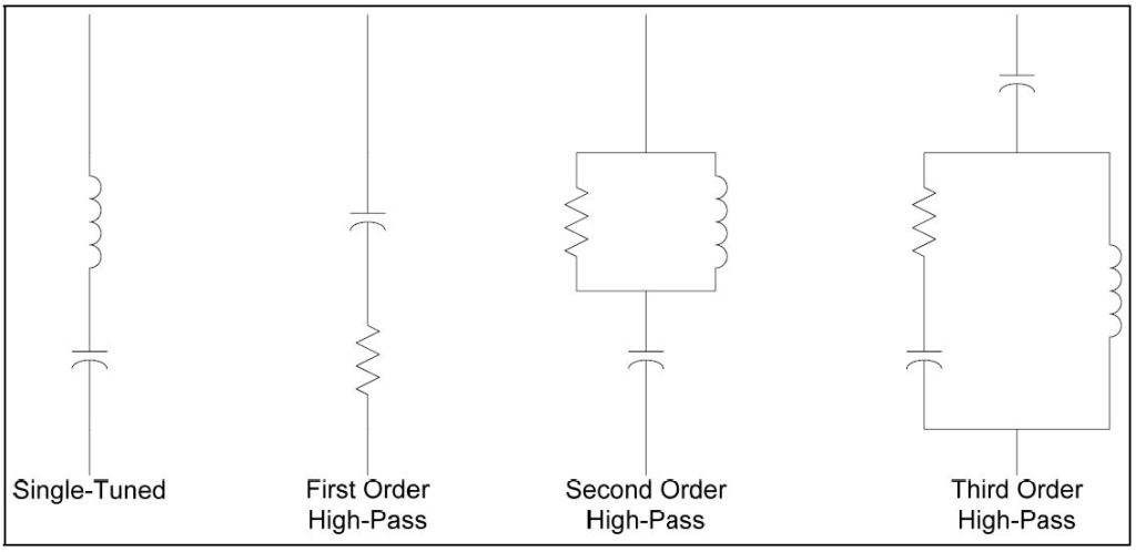
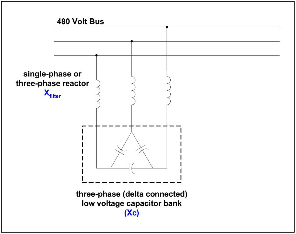
The most common type of passive filter is the single-tuned notch filter. This is the most economical type and is frequently sufficient for the application. An example of a common 480 volt filter arrangement is illustrated in Figure 7. The notch filter is series-tuned to present low impedance (see Figure 5) to a particular harmonic current. It is connected in shunt with the power system. Thus, harmonic currents are diverted from their normal flow path on the line into the filter. Notch filters can provide power factor correction in addition to harmonic suppression. Figure 7 shows a common delta-connected low-voltage capacitor bank converted into a filter by adding an inductance in series (note that higher rated voltage capacitor units should be used in filter applications, e.g., 600 volt capacitors on a 480 volt bus). In this case, the notch harmonic, hnotch, may be determined using:
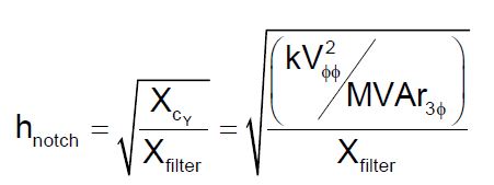
where:
XCY = equivalent wye capacitive reactance (Ω)
Xf = inductive reactance of filter reactor (Ω)
kVφφ = system rms phase-to-phase voltage (kV)
MVAr3φ = three-phase capacitor bank rating (MVAr)
One important side effect of adding a filter is that it creates a sharp parallel resonance point at a frequency below the notch frequency (see Figure 5). This resonant frequency must be placed safely away from any significant harmonic. Filters are commonly tuned slightly lower than the harmonic to be filtered to provide a margin of safety in case there is some change in system parameters. If they were tuned exactly to the harmonic, changes in either capacitance or inductance with temperature or failure might shift the parallel resonance higher into the harmonic. This could present a situation worse than no filter because the resonance is generally very sharp. For this reason, filters are added to the system starting with the lowest problem harmonic. For example, installing a 7th harmonic filter usually requires that a 5th harmonic filter to have been installed first. The new parallel resonance with a 7th harmonic filter only would have been near the 5th harmonic. When the two are operated side-by-side, the 5th harmonic filter must be energized first and de-energized last.
A delta-connected (capacitor) filter (see Figure 7) does not admit zero-sequence currents because the capacitor is connected in delta. This makes it largely ineffective for filtering zero-sequence triplen harmonics. Other solutions must be employed when it becomes necessary to control zero-sequence 3rd harmonic currents. For capacitors connected in wye, the designer has the option of altering the path for the zero-sequence triplen harmonics simply by changing the neutral connection. Placing a reactor in the neutral of a capacitor is a common way to force the bank to filter only zero-sequence harmonics. This technique is often employed to eliminate telephone interference.
Passive filters should always be placed on a bus where the short circuit impedance (XSC) can be expected to remain relatively constant. While the notch frequency is determined by the filter tuning, and will remain fixed, the parallel resonance will move as the system short circuit impedance varies. For example, one common problem occurs in factories that have standby generation for emergencies. The parallel resonant frequency for running with standby generation alone is generally much lower than when interconnected with the utility. This may shift the parallel resonance down into a harmonic where successful operation is impossible. Filters often have to be removed for standby operation because of this. Filters must also be designed with the capacity of the bus in mind. The temptation is to size the current-carrying capability based solely on the load that is producing the harmonic. However, even a small amount of background voltage distortion on a very strong bus may impose severe duty on the filter.
SUMMARY
Power factor correction is an important facet of power quality. Capacitors may be installed on customer systems to minimize charges for poor power factor on their electric bill. These installations may create problems by altering the harmonic frequency response of the network or introducing transient disturbances during their energization. This case study presented an overview of the impact of power factor correction on harmonics issues, such as parallel and series resonance and the effect of configuring capacitors as harmonic filters.
REFERENCES
IEEE Recommended Practice for Electric Power Distribution for Industrial Plants (IEEE Red Book, Std 141-1986), October 1986, IEEE, ISBN: 0471856878
IEEE Recommended Practice for Industrial and Commercial Power Systems Analysis (IEEE Brown Book, Std 399-1990), December 1990, IEEE, ISBN: 1559370440
IEEE Recommended Practice for Protection and Coordination of Industrial and Commercial Power Systems, March 1988, IEEE, ISBN: 0471853925
RELATED STANDARDS
IEEE Std. 519
GLOSSARY AND ACRONYMS
ASD: Adjustable-Speed Drive
DPF: Displacement Power Factor
PWM: Pulse Width Modulation
THD: Total Harmonic Distortion
TPF: True Power Factor
