Published by Electrotek Concepts, Inc., PQSoft Case Study: General Reference – Power Factor Correction, Document ID: PQS0311, Date: April 16, 2003.
Abstract: Simply stated, power factor is a measurement of how efficiently a facility uses electrical energy. A high power factor means that electrical power is being utilized effectively, while a low power factor indicates poor utilization of electric power.
Low power factor because it means that you are using the facility’s electrical system inefficiently. It can also cause equipment overloads, low voltage conditions, and greater line losses. Most importantly, low power factor can increase total demand charges and cost per kWh, resulting in higher monthly electric bills. This document provides an overview of the concept of power factor, including impacts on the electrical distribution system, effects on power quality, benefits of improvements, and estimating financial savings.
INTRODUCTION TO POWER FACTOR
A large number of customer loads in a modern electrical system are inductive, which means that they require an electromagnetic field to operate. Inductive loads, such as motors, require two kinds of electric power:
- Active Power (also known as “working power”) – powers equipment and performs useful work, such as creating heat, light, motion, etc.
- Reactive (magnetizing) Power – sustains an electromagnetic field (flux necessary to operate an inductive device).
Power factor involves the relationship between these two types of power. Active Power is measured in kilowatts (kW) and Reactive Power is measured in kilovolt-amperes-reactive (kVAr). Active power and reactive power together make up Apparent Power, which is measured in kilovolt-amperes (kVA). This relationship is often illustrated using the familiar “power” triangle (Figure 1):

Power factor measures how effectively electrical power is being used. Power factor is the ratio between active power (kW) and apparent power (kVA). Active power does work and reactive power produces an electromagnetic field for inductive loads. Using the values in the power triangle example, the facility is operating at 400 kW (Active Power) with an 80% power factor, resulting in a total load of 500 kVA.
Low power factor means that you are using a facility’s electrical system inefficiently. It can also cause equipment overloads, low voltage conditions, and greater line losses. Most importantly, low power factor can increase total demand charges and cost per kWh, resulting in higher monthly electric bills.
Effect of Load on Power Factor
Lightly-loaded or varying-load inductive equipment such as HVAC systems, induction furnaces, molding equipment, presses, etc. One of the worst offenders is a lightly loaded induction motor. Examples of equipment with:
- 85% power factor or better – incandescent lighting, diode rectifiers (small adjustable-speed drives (ASDs)), electronic ballasts, most electronic power supplies (personal computers, and office equipment).
- 70% – 85% power factor – induction motors (air conditioners, pumps, grinders, fans, and blowers).
- 70% power factor or worse – dc-drives (printing presses, elevators), single-strike presses, automated machine tools, finish grinders, and welders.
Benefits of Improving Power Factor
The principle benefit is lower monthly electric bills. Additional benefits include:
- More efficient use of the electrical system
- Improved voltage regulation due to reduced line voltage drop
- Increased load carrying capabilities in existing circuits
- Possible reduction in size of transformers, cables, and switchgear for new installations
- Reduced power system losses
Most Common Method for Improving Power Factor?
Low power factor is generally solved by adding power factor correction capacitors to a facility’s electrical distribution system. Power factor correction capacitors supply the necessary reactive portion of power (kVAr) for inductive devices. By supplying its own source of reactive power, a facility frees the utility from having to supply it. This generally results in a reduction in total customer demand and energy charges.
Power factor correction capacitors are rated in electrical terms called “VArs”. One VAr is equivalent to one volt-amp of reactor power. Since reactive power is generally measured in thousands of vars, the letter “k” (abbreviation for kilo) proceeds the Var creating the more familiar “kVAr” term. Therefore, a capacitor kVAr rating indicates how much reactive power the capacitor will supply.
The amount of power factor correction that is required to correct a facility to a target power factor level is the difference between the amount of kVAr in the uncorrected system (required by loads) and the amount of kVAr in the corrected system. A capacitor application is illustrated in the following power triangle (Figure 2):
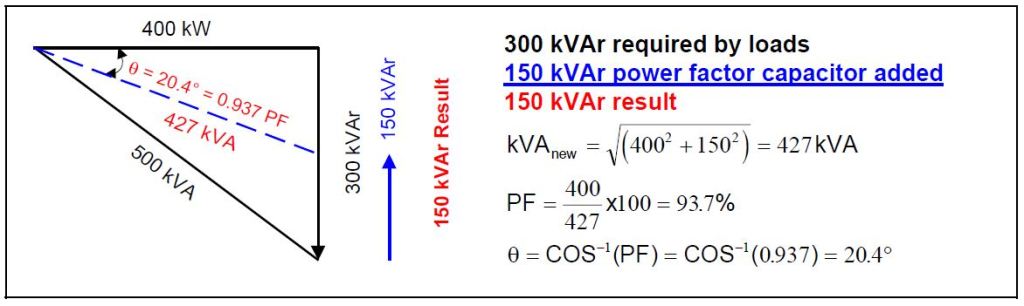
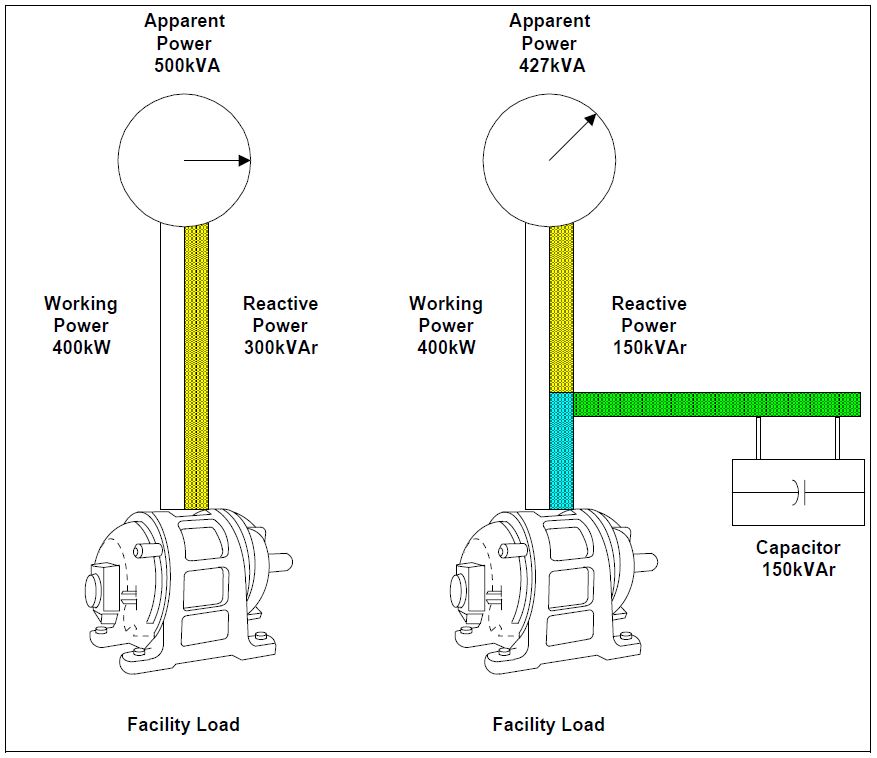
The location that provides the maximum benefits of power factor correction is at the load. Capacitors work from the point of installation back to the generating source. However, individual load (e.g. motor – shown in Figure 3) correction is not always practical and ongoing maintenance may become an issue as well. Sometimes it is more effective to connect larger capacitor banks to the main distribution bus, or to install automatic systems at the incoming service in conjunction with fixed capacitors at distributed loads.
IMPACT OF POWER FACTOR ON POWER QUALITY
A properly designed capacitor application should not have an adverse affect on equipment or power quality. However, despite the significant benefits that can be realized using power factor correction capacitors, there are a number of power quality-related concerns that should be considered if you install capacitors. Potential problems include increased harmonic distortion and transient overvoltages.
Harmonic Issues
Harmonic distortion on power systems can best be described as noise that distorts the sinusoidal wave shape. Harmonics are caused by nonlinear loads (e.g. ASDs, compact fluorescent lighting, induction furnaces, etc.) connected to the power system. These loads draw nonsinusoidal currents (on a 60 Hz system, the 5th harmonic is equal to 300 Hz), which in turn react with the system impedance to produce voltage distortion. Generally, the harmonic impedances are low enough that excessive distortion levels do not occur. However, power factor correction capacitors can significantly alter this impedance and create what is known as a “resonance” condition. High voltage distortion can occur if the resonant frequency is near one of the harmonic currents produced by the nonlinear loads. A method for estimating the resonance point (hresonance) is shown in the following example:

Indications that a harmonic resonance exists include device overheating, frequent circuit breaker tripping, unexplained fuse operation, capacitor failures, and electronic equipment malfunction. Ways to avoid excessive distortion levels include altering (or moving) the capacitor size to avoid a harmful resonance point (e.g. 5th, 7th), altering the size (or moving) of the nonlinear load(s), or adding reactors to the power factor correction capacitors to configure them as harmonic filters.
Harmonic Filter Applications
In general, both harmonic problems and switching transient problems can be solved by configuring power factor correction capacitors as a “tuned bank”. This involves adding a series reactor (Xf) to the capacitor bank to form a tuned circuit (resulting in low impedance at a specific frequency).
It is common to tune the filter below the 5th harmonic (e.g. 4.7th) for most industrial facilities. It is important to note that the addition of a series reactor results in a voltage rise on the capacitor, which often means that capacitors with a higher voltage rating are required. Figure 4 illustrates a tuned filter bank using 300 kVAr capacitors rated 600 volts.

Transient Overvoltage Issues
Transient overvoltages can be caused by a number of power system switching events, however, utility capacitor switching often receives special attention due to the impact on customer equipment. Each time a utility switches a capacitor bank a transient overvoltage occurs. Generally, these overvoltages are low enough that they do not affect the customer’s system. However, high overvoltages can occur when customers have power factor correction capacitors. This phenomenon is often referred to as “voltage magnification”. Magnification occurs when the transient oscillation initiated by the utility capacitor switching excites a resonance (refer to previous definition) formed by the step-down transformer and low voltage power factor correction capacitors. Magnified overvoltages can be quite severe and the energy associated with these events can be damaging to power electronic equipment and surge protective devices (e.g. transient voltage surge suppressor – TVSS). ASDs have been found to be especially susceptible to these transients and nuisance tripping can result even when overvoltage levels are not severe.
Ways to avoid excessive voltage levels due to utility capacitor switching include altering (or moving) the capacitor size to avoid a harmful resonance point, adding high-energy low-voltage arresters (metal-oxide varistors – MOVs), or adding reactors to power factor correction capacitors to configure them as harmonic filters. The probability of nuisance tripping of ASDs can be significantly reduced by adding reactors (also known as “chokes”) to the drives.
Before investing in power factor correction capacitors, it is prudent to have the electrical system carefully analyzed to avoid potential problems with excessive transient voltages and harmonic distortion levels.
Estimating Financial Savings
A monthly electric bill will include an additional surcharge if the rate schedule has a “power factor penalty” and the power factor is below a specific level (such as 95%). This penalty can be reduced or completely eliminated with the proper application of power factor correction capacitors. The savings realized needs to be weighed against the equipment costs to determine if the payback period is acceptable. Payback times can vary significantly due to wide range of low voltage capacitor costs (e.g. approximately $15/kVAr for fixed capacitors to $75/kVAr for adjustable filter banks).
Example Illustrating Capacitor Sizing and Payback Estimation:
Consider the following example data. Please note that this example is provided to illustrate one possible method for determining a power factor correction capacitor size and payback period. You will need to utilize your billing and rate schedule data for an accurate calculation
Example Data:
Energy Rate: $0.05/kWh
Demand Charge: $9.00/kW
Month: June
Number of Days: 30
Energy Use: 325000kWh
Demand: 800kW
Power Factor: 80%
Assumed Low Voltage Power Factor Correction Capacitor Cost: $20/kVAr
Step 1:
Determine Energy and Demand Components of the Monthly Bill:
Energy Use (kWh) * Energy Rate ($/kWh)
325,000 kWh * $0.05/kWh = $16,250
Demand (kW) * Demand Charge ($/kW)
800 kW * $9.00/kW = $7,200
Total Energy and Demand Components = $23,450
Step 2:
Determine Monthly Power Factor Penalty:
$(Total Energy and Demand Components) * (95 – Power Factor) * 0.0025
$23,450 * (95 – 80) * 0.0025 = $879
Step 3:
Determine Average Active Load (kW):
Energy Use (kWh) / (Number of Days * 24hours/day)
325,000 kWh / (30 * 24) = 451 kW
Step 4:
Determine Capacitor Rating to Correct Power Factor to 95%:
kVAr95% = (Average Active Load) * [TAN(COS-1(Power Factor)) – TAN(COS-1(0.95))]
451 kW * [TAN(COS-1(0.80)) – TAN(COS-1(0.95))]
190 kVAr (will purchase a 200 kVAr, 480 volt capacitor bank)
Step 5:
Estimate Equipment and Installation Cost:
Capacitor Bank Cost = 200 kVAr * $20/kVAr = $4,000
Estimated Installation Cost = $1,000
Total Cost = $5,000
Step 6:
Determine Payback Period:
Payback (in months) = Total Cost / Monthly Power Factor Penalty
$5,000 / $879 = 5.7 months
Note that this analysis only illustrates a simple payback and does not include operating and maintenance costs (generally low for low-voltage fixed capacitor banks), the cost of capital, or interest rates.
SUMMARY
Power factor is a measurement of how efficiently a facility uses electrical energy. A high power factor means that electrical power is being utilized effectively, while a low power factor indicates poor utilization of electric power.
Low power factor can cause equipment overloads, low voltage conditions, and greater line losses. Most importantly, low power factor can increase total demand charges and cost per kWh, resulting in higher monthly electric bills.
Low power factor is generally solved by adding power factor correction capacitors to a facility’s electrical distribution system. Power factor correction capacitors supply the necessary reactive portion of power (kVAr) for inductive devices. The principle benefit is lower monthly electric bills.
REFERENCES
IEEE Recommended Practice for Electric Power Distribution for Industrial Plants (IEEE Red Book, Std 141-1986), October 1986, IEEE, ISBN: 0471856878
IEEE Recommended Practice for Industrial and Commercial Power Systems Analysis (IEEE Brown Book, Std 399-1990), December 1990, IEEE, ISBN: 1559370440
IEEE Recommended Practice for Protection and Coordination of Industrial and Commercial Power Systems, March 1988, IEEE, ISBN: 0471853925
Industrial and Commercial Power Systems Handbook, F. S. Prabhakara, Robert L. Smith, Ray P. Stratford, November 1995, McGraw Hill Text, ISBN: 0070506248
RELATED STANDARDS
IEEE Standard 519-1992
IEEE Standard 18-1992
IEEE Standard 1036-1992
GLOSSARY AND ACRONYMS
ASD: Adjustable-Speed Drive
HVAC: High-Voltage Air Conditioning
MOV: Metal Oxide Varistor
PF: Power Factor
PWM: Pulse Width Modulation
TVSS: Transient Voltage Surge Suppressors
