Published by Vedant S. Samudre, Department of electrical, electronics & power, Jawaharlal, Nehru Engineering College, Aurangabad, Maharashtra, India
Published in International Journal of Engineering Sciences & Research Technology (IJESRT)
Website: www.ijesrt.com
Samudre* et al., 5(12): December, 2016
DOI: 10.5281/zenodo.192584
ABSTRACT
Power quality is one of the major concerns and emerging issues in the present era. With increasing quantities of non-linear loads being added to electrical systems, it has become necessary to investigate the power quality issues as all electrical devices are prone to failure when exposed to one or more power quality problems. This paper highlights power quality problems, effect of power quality problems in different apparatuses and methods for its correction. This paper will be very much helpful for engineers, technicians, designers, researchers and system operators as it is necessary for them to become familiar with power quality issues.
KEYWORDS: Power quality (PQ), Standards, Problems.
INTRODUCTION
Power quality problem in the power system has gained importance since the late 1980s. The interest in Power Quality (PQ) is related to all three parties concerned with the power i.e. utility companies, equipment manufacturers and electric power consumers. Problems affecting the electricity supply that were once considered tolerable by the electric utilities and users are now often taken as a problem to the users of everyday equipment. Understanding power quality can be confusing at best. There have been numerous articles and books concerning power quality [1]. There are two terms known in power systems about the quality of power: Good power quality and poor power quality. Good power quality can be used to describe a power supply that is always available, always within the voltage and frequency tolerances and has a pure noise-free sinusoidal wave shape to all equipment, because most equipment was designed on that basis [4]. Unfortunately, most of the equipment that is manufactured also distorts the voltage [3] on the distribution system, leading to what is known as poor power quality. And thus affecting other equipment that was designed with the expectation of consistent undistorted voltage, and are thus sensitive [2] to power disturbances resulting in reduced performance and will cause equipment miss operation or premature failure. The cost of power quality problems can be very high and include the cost of downtimes, loss of customer confidence and, in some cases, equipment damage.
MATERIALS AND METHODS
Why power quality is important?
Along with technology advance, the organization of the worldwide economy has evolved towards globalization and the profit margins of many activities tend to decrease. The increased sensitivity of the vast majority of processes (industrial, services and even residential) to PQ problems turns the availability of electric power with quality a crucial factor for competitiveness in every activity sector. The most critical areas are the continuous process industry and the information technology services. [5] The performance of electronic devices is directly linked to the power quality level. Quality phenomenon or power quality disturbance can be defined as the deviation of the voltage and the current from its ideal waveform.. Faults at either the transmission or distribution level may cause voltage sag or swell in the entire system or a large part of it. Also, under heavy load conditions, a significant voltage drop may occur in the system. Voltage sag and swell can cause sensitive equipment to fail, shutdown and create a large current unbalance. These effects can incur a lot of expensive from the customer and cause equipment damage. So , in order to provide uninterrupted power to the service sectors as well as others for economic growth and prevent equipment damage with varying voltage level and frequency, undoubtedly power quality improvement is utmost important.
Power quality standards
Power quality is a worldwide issue and its related standards [6] being used by researchers, designer and practitioner to improve power quality are given below:
IEEE 519
IEEE 519-1992, Recommended Practices and Requirements for Harmonic Control in Electric Power Systems, established limits on harmonic currents and voltages at the point of common coupling (PCC), or point of metering [7,20]. The limits of IEEE 519 are intended to:
1) Assure that the electric utility can deliver relatively clean power to all of its customers
2) Assure that the electric utility can protect its electrical equipment from overheating, loss of life from excessive harmonic currents, and excessive voltage stress due to excessive harmonic voltage. Each point from IEEE 519 lists the limits for harmonic distortion at the point of common coupling (PCC) or metering point with the utility. The voltage distortion limits are 3% for individual harmonics and 5% THD. All of the harmonic limits in IEEE 519 are based on a customer load mix and location on the power system.
IEEE 519 Standard for Current Harmonics:
- General Distribution Systems [120V- 69 kV]: Below current distortion limits are for odd harmonics. Even harmonics are limited to 25% of the odd harmonic limits [7, 9, and 11]. For all power generation equipment, distortion limits are those with ISC/IL<20.ISC is the maximum short circuit current at the point of coupling “PCC”.IL is the maximum fundamental frequency 15-or 30- minutes load current at PC.
- General Sub-transmission Systems [69 kV-161 kV]: The current harmonic distortion limits apply to limits of harmonics that loads should draw from the utility at the PCC. Note that the harmonic limits differ based on the ISC/IL rating, where ISC is the maximum short circuit current at the PCC, and I is the maximum demand load current at the PCC.
Table no. 1: Current distortion limit for harmonics.
| ISC/IL | h<11 | 11≤h<17 | 17≤h≤23 | 23≤h<25 | TDD (%) |
|---|---|---|---|---|---|
| <20 | 4.0 | 2.0 | 1.5 | 0.6 | 5 |
| 20-50 | 7.0 | 3.5 | 2.5 | 1.0 | 8 |
| 50-100 | 10 | 4.5 | 4.0 | 1.5 | 12 |
| 100-1000 | 12 | 5.5 | 5.0 | 2.0 | 15 |
| >1000 | 15 | 7.0 | 6.0 | 2.5 | 20 |
IEEE Standard For Voltage Harmonics:
The voltage harmonic distortion limits apply to the quality of the power. For instance, for systems of less than 69 kV, IEEE 519 requires limits of 3 percent harmonic distortion for an individual frequency component and 5 percent for total harmonic distortion.
Table no. 2: Voltage distortion limit for harmonics.
| Bus Voltage | Individual Vh (%) | THDV (%) |
|---|---|---|
| V<69 kV | 3.0 | 5.0 |
| 69≤V<161 kV | 1.5 | 2.5 |
| V≥161 kV | 1.0 | 1.5 |
IEC 61000-3-2 and IEC 61000-3-4 (formerly 1000-3-2 and 1000-3-4)
IEC 61000-3-2 (1995-03)
It specifies limits for harmonic current emissions applicable to electrical and electronic equipment having an input current up to and including 16 A per phase, and intended to be connected to public low-voltage distribution systems. The tests according to this standard are type tests. [8, 15, 19]
IEC/TS 61000-3-4 (1998-10)
It specifies to electrical and electronic equipment with a rated input current exceeding 16 A per phase and intended to be connected to public low-voltage ac distribution systems of the following types:
- nominal voltage up to 240 V, single-phase, two or three wires;
- nominal voltage up to 600 V, three-phase, three or four wires
- nominal frequency 50 Hz or 60 Hz
These recommendations specify the information required to enable a supply authority to assess equipment regarding harmonic disturbance and to decide whether or not the equipment is acceptable for connection with regard to the harmonic distortion aspect. The European standards, IEC 61000-3-2 & 61000-3-4, placing current harmonic limits on equipment, are designed to protect the small consumer’s equipment. The former is restricted to 16 A; the latter extends the range above 16 A.
IEEE Standard 141-1993, Recommended Practice for Electric Power Distribution for Industrial Plants A thorough analysis of basic electrical-system considerations is presented. Guidance is provided in design, construction, and continuity of an overall system to achieve safety of life and preservation of property; reliability; simplicity of operation; voltage regulation in the utilization of equipment within the tolerance limits under all load conditions; care and maintenance; and flexibility to permit development and expansion.
IEEE Standard 142-1991, Recommended Practice for Grounding of Industrial and Commercial Power Systems This standard presents a thorough investigation of the problems of grounding and the methods for solving these problems.[9,12]
IEEE Standard 446-1987, Recommended Practice for Emergency and Standby Power Systems for Industrial and Commercial Applications This standard is recommended engineering practices for the selection and application of emergency and standby power systems.[12]
IEEE Standard 493-1997, Recommended Practice for Design of Reliable Industrial and Commercial Power Systems
The fundamentals of reliability analysis as it applies to the planning and design of industrial and commercial electric power distribution systems are presented. Included are basic concepts of reliability analysis by probability methods, fundamentals of power system reliability evaluation, economic evaluation of reliability, cost of power outage data, equipment reliability data, and examples of reliability analysis. Emergency and standby power, electrical preventive maintenance, and evaluating and improving reliability of the existing plant are also addressed.[10,12,13,14]
IEEE Standard 1100-1999, Recommended Practice for Powering and Grounding Sensitive Electronic Equipment
Recommended design, installation, and maintenance practices for electrical power and grounding (including both power-related and signal-related noise control) of sensitive electronic processing equipment used in commercial and industrial applications. [12, 14]
IEEE Standard 1159-1995, Recommended active for Monitoring Electric Power Quality
As its title suggests, this standard covers recommended methods of measuring power-quality events. Many different types of power-quality measurement devices exist and it is important for workers in different areas of power distribution, transmission, and processing to use the same language and measurement techniques. Monitoring of electric power quality of AC power systems, definitions of power quality terminology, impact of poor power quality on utility and customer equipment, and the measurement of electromagnetic phenomena are covered.[11,14,16,17,18]
CLASSIFICATION OF POWER SYSTEM DISTURBANCES
Power quality problems occur due to various types of electrical disturbances. Most of the EPQ disturbances depend on amplitude or frequency or on both frequency and amplitude. Based on the duration of existence of EPQ disturbances, events can divided into short, medium or long type. The disturbances causing power quality degradation arising in a power system and their classification mainly include:
Interruption/under voltage/over voltage
These are very common type disturbances.
During power interruption, voltage level of a particular bus goes down to zero. The interruption may occur for short or medium or long period. Under voltage and over voltage are fall and rise of voltage levels of a particular bus with respect to standard bus voltage. Sometimes under and over voltages of little percentage is allowable; but when they cross the limit of desired voltage level, they are treated as disturbances. Such disturbances are increasing the amount of reactive power drawn or deliver by a system, insulation problems and voltage stability.
Voltage/current unbalance
Voltage and current unbalance may occur due to the unbalance in drop in the generating system or transmission system and unbalanced loading. During unbalance, negative sequence components appear.
Transients
Transients may generate in the system itself or may come from the other system. Transients are classified into two categories: dc transient and ac transient.AC transients are further divided into two categories: single cycle and multiple cycles. [21, 22]
Voltage sag
It is a short duration disturbance. [23] During voltage sag, r. m. s. voltage falls to a very low level for short period of time.
Voltage swell
It is a short duration disturbance. During voltage sag, r. m. s. voltage increases to a very high level for short period of time.
Harmonic
Harmonics are the alternating components having frequencies other than fundamental present in voltage and current signals. There are various reasons for harmonics generation like non linearity, excessive use of semiconductor based switching devices, different design constrains, etc. Harmonics have adverse effects on generation, transmission and distribution system as well as on consumer equipment’s also. Harmonics are classified as integer harmonics, sub harmonics and inter harmonics. Integer harmonics have frequencies which are integer multiple of fundamental frequency, sub harmonics have frequencies which are smaller than fundamental frequency and inter harmonics have frequencies which are greater than fundamental frequencies. Among these entire harmonics integer and inter harmonics are very common in power system. Occurrence of sub harmonics is comparatively smaller than others. Sometimes harmonics are classified: time harmonics and spatial (space) harmonics. Obviously their causes of occurrence are different. Harmonics are in general are not welcome and desirable. Harmonics are assessed with respect to fundamental. Monitoring of harmonics with respect to fundamental is important consideration in power system application For this purpose different distortion factor with respect to the fundamental have been introduced.
Flicker
It is undesired variation of system frequency.
Ringing waves
Oscillatory disturbances of decaying magnitude for short period of time is known as ringing wave. It may be called a special type transient. The frequency of a flicker may or may not be same with the system frequency.
Outages
It is special type of interruption where power cut has occurred for not more than 60s.
POWER QUALITY SOLUTIONS
Power conditioning devices
Following devices play a crucial role in improving power quality strategy.
Transient Voltage surge suppressor (TVSS)
It provides the simplest and least expensive way to condition power. These units clamp transient impulses (spikes) to a level that is safe for the electronic load. Transient voltage surge suppressors are used as interface between the power source and sensitive loads, so that the transient voltage is clamped by the TVSS before it reaches the load. TVSS usually contain a component with a nonlinear resistance (a metal oxide varistor or a Zener diode) that limits excessive line voltage and conduct any excess impulse energy to ground. [24]
Filter
Filters are categorized into noise filters, harmonic filters (active and passive) etc. [25] Noise filters are used to avoid unwanted frequency current or voltage signals (noise) from reaching sensitive equipment. This can be accomplished by using a combination of capacitors and inductances that creates a low impedance path to the fundamental frequency and high impedance to higher frequencies, that is, a low-pass filter. Harmonic filters are used to reduce undesirable harmonics. Passive filters consist in a low impedance path to the frequencies of the harmonics to be attenuated using passive components (inductors, capacitors and resistors)
Motor generator set
They are usually used as a backup power source for a facility’s critical systems such as elevators and emergency lighting in case of blackout. However, they do not offer protection against utility power problems such as over voltages and frequency fluctuations. Motor generators are consists of an electric motor driving a generator with coupling through a mechanical shaft. This solution provides complete decoupling from incoming disturbances such as voltage transients, surges and sags.
Isolation transformer
Isolation transformers [26] are used to isolate sensitive loads from transients and noise deriving from the mains. The particularity of isolation transformers is a grounded shield made of nonmagnetic foil located between the primary and the secondary. Any noise or transient that come from the source in transmitted through the capacitance between the primary and the shield and on to the ground and does not reach the load. Isolation transformers reduce normal and common mode noises, however, they do not compensate for voltage fluctuations and power outages. [26]
Voltage regulators
Voltage regulators are normally installed where the input voltage fluctuates, but total loss of power is uncommon. There are three basic types of regulators:
- Tap changers: Designed to adjust for varying input voltage by automatically transferring taps on a power transformer.
- Buck boost: Utilize similar technology to the tap changers except transformer is not isolated.
- Constant voltage transformer (CVT): It is completely static regulator that maintains nearly constant output voltage during large variation in input voltage.
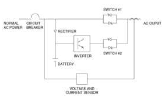
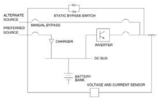
Uninterrupted power supply (UPS)
UPS systems provide protection in the case of a complete power interruption (blackout). They should be applied where “down time” resulting from any loss of power is unacceptable. UPS are designed to provide continuous power to the load in the event of momentary interruptions. They also provide varying degrees of protection from surges, sags, noise or brownouts depending on the technology used. [24]
There are three major UPS topologies each providing different levels of protection:
- Offline UPS: Low cost solution for small, less critical, stand-alone application such as PLC, personal computers and peripherals. Advantages of offline UPS are high efficiency, low cost and high reliability.
- Line interactive UPS: These UPS provides highly effective power conditioning plus battery backup. Advantages are good volume regulation and high efficiency. Disadvantages are noticeable transfer time and difficulty in comparing competing units.
- True Online UPS: It provides the highest level of power protection, conditioning and power availability. Advantages includes the elimination of any transfer time and superior protection from voltage fluctuation.
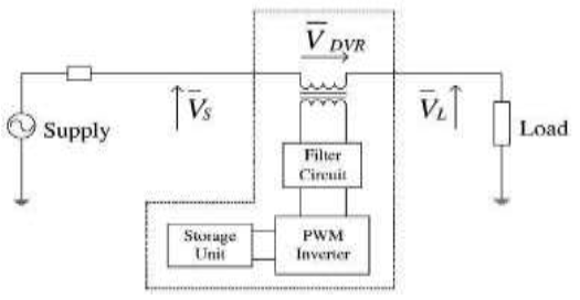
Dynamic Voltage Regulator (DVR)
A dynamic voltage restorer (DVR) acts like a voltage source connected in series with the load. The output voltage of the DVR is kept approximately constant voltage at the load terminals by using a step-up transformer and/or stored energy to inject active and reactive power in the output supply through a voltage converter. [27]
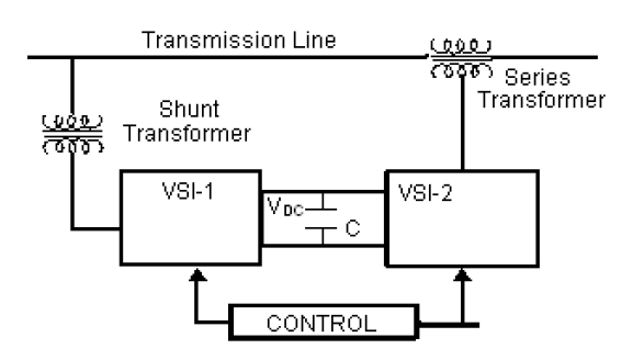
Unified Power Quality Conditioner (UPQC)
The UPQC employs two voltage source inverters (VSI) that is connected to a dc energy storage capacitor .A UPQC, combines the operations of a Distribution Static Compensator (DSTATCOM) and Dynamic Voltage Regulator (DVR) together. This combination allows a simultaneous compensation of the load currents and the supply voltages, so that compensated current drawn from the network and the compensated supply voltage delivered to the load are sinusoidal and balanced. [28]
Thyristor based switch
The static switch is a versatile device for switching a new element into the circuit when voltage support is needed. To correct quickly for voltage spikes, sags, or interruptions, the static switch can be used to switch in capacitor, filter, alternate power line, energy storage system etc. It protects against 85% of the interruptions and voltage sags. [28]
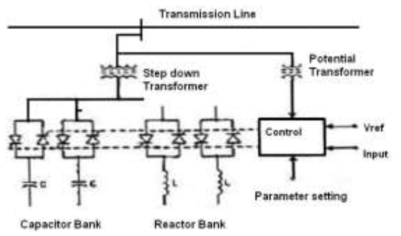
Static VAR compensator (SVC)
Static VAR compensators (SVC) use a combination of capacitors and reactors to regulate the voltage quickly. Solid-state switches control the insertion of the capacitors and reactors at the right magnitude to prevent the voltage from fluctuating. It is normally applied to transmission networks to counter voltage dips/surges during faults. [24]
CONCLUSION
An extensive review of work done power quality issues has been presented to provide a clear perspective on various aspects of the power quality to the researchers and engineers working in this field. To overcome the negative impact of poor power quality on equipment and businesses, suitable power quality equipment can be invested.
REFERENCES
[1] “Details of equipment sensitivity,” http://www.powerquality.com/pqpark/pqpk1052.hm
[2] A. Rash, “Power quality and harmonics in the supply network: a look at common practices and standards,” in Proc. On MELECON’ 98, Vol.2, pp.1219-1223, May1998
[3] R.C. Sermon, “An overview of power quality standards and guidelines from the end-user’s point-of-view,” in Proc. Rural Electric Power Conf., pp. 1-15, May 2005
[4] IEC 61000-4-30, “Testing and measurement techniques – Power quality measurement methods,” pp. 19, 78, 81, 2003
[5] Ferracci, P., “Power Quality”, Schneider Electric Cahier Technique no. 199, September 2000.
[6] S. Khalid et al “Power quality issues, problems, standards & their effects in industry with corrective means” International Journal of Advances in Engineering & Technology(IJAET),vol-1,issue 2, pp 1-11,May 2011.
[7] IEEE, “IEEE Recommended Practices and Requirements for Harmonic Control in Electrical Power Systems,” IEEE Std. 519-1992, revision of IEEE Std. 519-1981
[8] IEC, Electromagnetic Compatibility, Part 3: Limits- Sect.2: Limits for Harmonic Current Emission,” IEC 1000-3-2, 1st ed., 1995
[9] V. K. Dhar, “Conducted EMI Analysis—A Case Study,” Proceedings of the International Conference on Electromagnetic Interference and Compatibility ‘99, December 6–8, 1999, pp. 181–186.
[10] IEEE, “IEEE Guide for Service to Equipment Sensitive to Momentary Voltage Disturbances,” IEEE Std. 1250–1995.
[11] IEEE, “IEEE Recommended Practice for Evaluating Electric Power System Compatibility with Electronic Process Equipment,” IEEE Std. 1346-1998.
[12] IEEE Std 446-1987, “IEEE Recommended Practice for Emergency and Standby Power Systems for Industrial and Commercial Applications,”
[13] IEEE Std 1250-1995, “IEEE Guide for Service to Equipment Sensitive to Momentary Voltage Disturbances,” Art 5.1.1, Computers.
[14] IEEE 100, The Authoritative Dictionary of IEEE Standard Terms, seventh edition, 2000, p. 234.
[15] Mohan, Underland and Robbins, Power Electronics, John Wiley and Sons, 1995.
[16] R. C. Dugan, M. F. McGranaghan, S. Santosa, and H. W. Beaty, Electrical Power Systems Quality, 2nd edition, McGraw-Hill, 2002.
[17] Blajszczak, G. Antos, P, “Power Quality Park – Idea and feasibility study,” Proc. Of Electric Power Quality and Supply Reliability Conference (PQ), 16-18 June, pp 17 – 22, 2010.
[18] S.Khalid, B.Dwivedi, “A Review of State of Art Techniques in Active Power Filters and Reactive Power Compensation,” National Journal of Technology, No 1, Vol. 3, pp.10-18, Mar. 2007.
[19] Alexander Kusko, Marc T. Thompson, “Power Quality in Electrical Systems, McGraw-Hill, New York, 2007.
[20] J. G. Boudrias, “Harmonic Mitigation, Power Factor Connection, and Energy Saving with Proper Transformers and Phase Shifting Techniques,” Proc. Of Power Quality Conference, ‘04, Chicago, IL
[21] Bollen, M.H.J., Styvaktakis, E., Yu-HuaGu, I.: Categorization and analysis of power system transients. IEEE Trans. Power Deliv. 20(3), 2298–2306 (2005)
[22] Herath, C., Gosbell,V., Perera, S.:A transient index for reporting power quality (PQ) surveys. Proceedings CIRED 2003, pp. 2.61-1–2.61-5. Bercelona, Spain (2003)
[23] Djokic, S.Z., Desmet, J., Vanalme, G., Milanovic, J.V., Stockman, K.: Sensitivity of personal computer to voltage sags and short interruption. IEEE Trans. Power Deliv. 20(1), 375–383 (2005)
[24] Marty Martin, “Common power quality problems and best practice solutions,” Shangri la Kuala Lumpur, Malaysia 14. 1997
[25] Singh, B., AL Haddad K., Chandra, A., “A review of active filters for power quality improvement,” IEEE Trans. Ind. Electron., Vol. 46, pp 960–970, 1999
[26] Arrillaga, J., Watson N.R., Chen, S., Power system quality assessment, John Wiley and Sons, 2000.
[27] Sabin D.D., Sundaram, A., “Quality enhances reliability”. IEEE Spectrum, Feb. 1996. 34 41.
[28] Anurag Agarwal, Sanjiv Kumar, Sajid Ali, “A Research Review of Power Quality Problems in Electrical Power System”. MIT International Journal of Electrical and Instrumentation Engineering, Vol. 2(2), pp. 88-93, 2012.

Article refers to IEEE-519 -1992 whereas it should refer to 2014 updated standards. The topic of mitigation with PQ issues have multiple solutions. It would have been good to have a table of pros and cons on various equipment.
LikeLike
Hello Tushar, thank you for your suggestions, comments and noted on the updates.
LikeLike