Published by Electrotek Concepts, Inc., PQSoft Case Study: General Reference – Performing Power Quality Audits, Document ID: PQS0306, Date: February 4, 2003.
Abstract: Power quality investigations often require monitoring to identify the exact problem and then to verify the solutions that are implemented. Before embarking on extensive monitoring programs, it is important to develop an understanding of the customer facility, equipment being affected, wiring and grounding practices, and operating considerations. Often, power quality problems can be solved without extensive monitoring by asking the right questions when talking to the customer and performing an initial power quality audit.
This document provides a guide for performing a power quality audit.
PERFORMING POWER QUALITY AUDITS
Power quality investigations often require monitoring to identify the exact problem and then to verify the solutions that are implemented. Before embarking on extensive monitoring programs, it is important to develop an understanding of the customer facility, equipment being affected, wiring and grounding practices, and operating considerations. Often, power quality problems can be solved without extensive monitoring by asking the right questions when talking to the customer and performing an initial site survey. Audit procedures generally include the following steps:
- Obtaining customer input
- Defining objectives (scope) of the work
- Collecting data and conducting an equipment inventory
- Wiring and grounding inspections
- Determining monitoring locations
- Selecting appropriate monitoring equipment
- Preparing an audit report
Utilities are generally blamed for power quality problems. They are not necessarily responsible. There are four sources for most customer-encountered problems:
- Natural phenomena (e.g., inclement weather)
- Normal utility operations (e.g., automatic protection system operations)
- Neighboring customers (e.g., welding equipment adjacent to an office)
- Customer’s own equipment and facilities.
While most problems have nothing to do with the utility, customers often blame the utility for causing or contributing to the problem. In fact, eighty percent of all power quality related problems in commercial and industrial facilities are caused on the customer side of the meter. In residential facilities, eighty percent of the problems are due to weather and weather-related actions.
The first step is to understand how customers perceive power quality problems. Customers rarely see or understand these problems. They see symptoms of them and the resulting difficulties in their businesses and homes.
Some of the more common symptoms include:
− Equipment damage
− Blinking digital displays
− Data or information loss / software glitches
− Loss of instructional programming and controller timing
− An abnormal number of service calls on sensitive equipment
− Disk drive problems / computers re-booting
− Static shock
Performing a Site Survey
Data Collection Process
The initial site survey should be designed to obtain as much information as possible about the customer facility and the problems being experienced. Specific information that should be obtained at this stage includes:
- Customer information:
a. company and contact name
b. address and phone/fax/e-mail
- Nature of the problems:
a. data or information loss
b. nuisance trips of motor drives or other power-electronic devices
c. electronic component failures
d. control system malfunctions
e. equipment damage
- Impact on operations:
a. stop or slow production
b. lost production or sales
c. reduced product quality
d. scrap / restart
- Characteristics of the sensitive equipment experiencing problems:
a. equipment design information
b. equipment ride-through characteristics
c. equipment application guides or installation/user manuals
- Frequency and timing:
a. time of day, day of week/month, dates of occurrence
b. repetitive (e.g., same time every day)
- Coincident problems or known operations that occur at the same time:
a. motor starting or slowing down
b. capacitor switching
c. lights blink on and off momentarily
d. weather conditions
- Possible sources of power quality variations within the facility:
a. motor starting
b. capacitor switching
c. power electronic equipment operation (e.g., ASDs, PCs, electronic ballast fluorescent lights)
d. arcing equipment (e.g., magnetic ballast fluorescent lights, arc furnaces, etc.)
e. copy machines, HVAC
- Power conditioning equipment being used:
a. surge suppressors (e.g., TVSS, arresters, etc.)
b. motor-generator sets
c. ferroresonant transformers (also know as CVTs)
d. UPS systems
e. isolation transformers / chokes
- Electrical system data:
a. oneline or facility wiring diagrams
b. transformer information (e.g., size and impedance)
c. load information
d. capacitor information (e.g., size, connection, and placement)
e. feeder/cable data
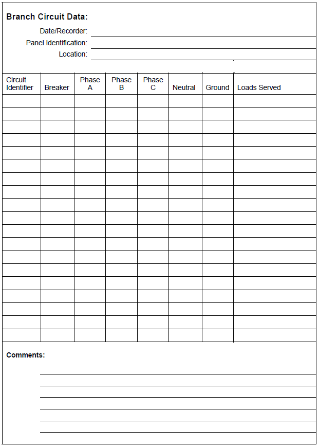
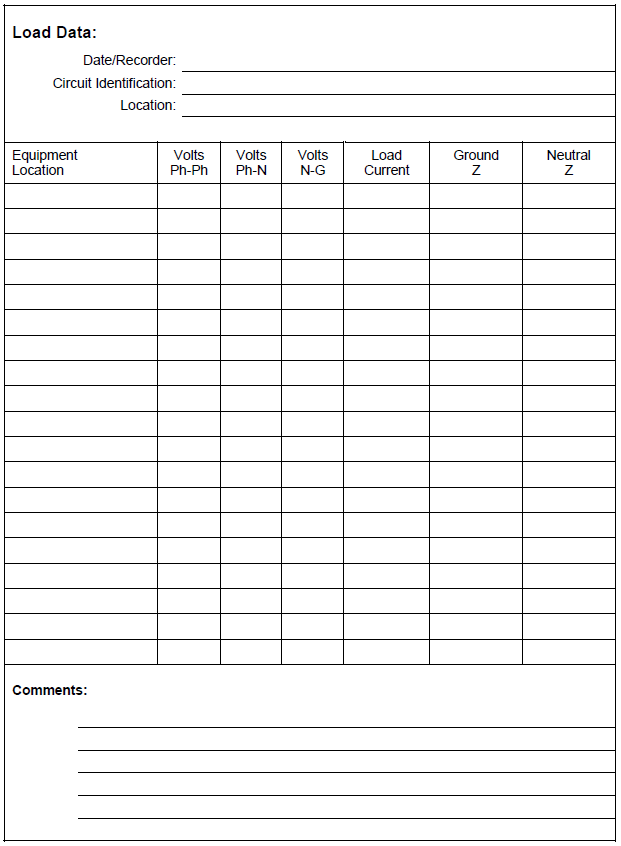
Data Recording Process
Once this basic data is obtained through discussions with the customer, a site survey should be performed to verify the oneline diagrams, electrical system data, wiring and grounding integrity, load levels, and basic power quality characteristics. Data forms that can be used for this initial verification of the power distribution system are provided in Figure 1 through Figure 4.

Performing Wiring and Grounding Inspections
Wiring and grounding problems are responsible for many power quality variations within customer facilities. Some electric utility engineers have estimated that 80% of all the power quality problems reported by customers are found to be due to their own wiring and grounding problems. While end-users may have a different opinion, it is commonplace for many power quality problems to be resolved by simply tightening a loose connection, removing an unnecessary ground connection, bonding ground conductors, or replacing a corroded conductor. Therefore, the first step in most power quality investigations is to evaluate the wiring and grounding practices of the facility.
Wiring and grounding problems are identified by physical inspections of wiring, connections etc.; infrared scans to identify heating that may be caused by overloaded conductors or bad connections; and measurements to characterize circuit loading and identify grounding problems. Steps for a wiring and grounding inspections include:
1. Check rms voltage levels.
2. Check for extra neutral-ground bonds. There should be only one neutral-to-ground bond per separately derived system. This is a common problem that causes load currents to flow in the building ground system, creating the potential for serious interference problems. This can be checked by measuring the current in the green wire grounds at the service entrance or at the source of the separately derived system. These currents should be very close to zero. If any current is flowing in the ground, the source of the current should be found and corrected.
3. Check for overloaded neutral conductors. In three-phase, four wire systems supplying single-phase electronic loads, the neutral currents can be as high as 173% of the rms phase current. This can cause overloading of the neutral conductor because the code does not require the neutral conductor to be rated for currents higher than the phase conductor. The neutral currents should be measured with a true rms meter and checked against the ampacity of the neutral conductors. This problem can be corrected by filtering the harmonics of the electronic loads, using a zig-zag transformer, reducing the load, or increasing the neutral conductor capacity.
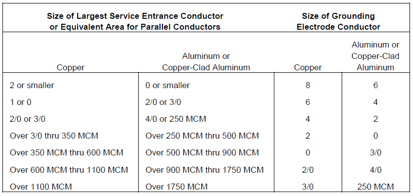
4. Checking grounding electrode system. The grounding electrode system consists of all the grounded elements of the building that are bonded together to form a grounding system. This can include ground rods, metal water pipe, building steel, concrete-encased electrodes, a ground ring, etc. All of these things should be bonded together to form the best equipotential reference for equipment in the building as possible. It is not advisable to have separate, isolated ground rods for individual equipment in the facility. If a separate ground rod is driven for equipment, it should be bonded with the overall building grounding electrode system. Guidelines for the grounding electrode conductor are provided in Table 1.
5. Check isolated ground receptacle wiring. Isolated ground receptacles are a good way to provide a separate, clean ground for sensitive equipment. These receptacles require a separate ground wire in addition to the safety ground. The isolated ground is insulated from the case of the receptacle and should go back to the ground of the separately derived system, where it is tied in to the building grounding electrode system.
Table 1 – Grounding Electrode Conductor for AC Systems
6. Check overall circuit layouts. Are sensitive equipment loads on separate circuits from disturbing loads? Loads that are switched or that have power electronic components can create transient disturbances that can impact the operation of some sensitive equipment. Loads like switched motors, copiers, laser printers, elevators, etc. should be on separate circuits from sensitive equipment. The separate circuits provide isolation for high frequency transients and a clean ground reference for the sensitive loads.
7. Check for use of separately derived systems. Separately derived systems permit the bonding of the ground and neutral. In circuits with significant neutral currents (e.g., single-phase electronic loads), a significant neutral-to-ground voltage will build up if there is a significant length between the loads and the supplying transformer. Using an isolation transformer close to the loads minimizes the neutral-to-ground voltage and provides isolation for transient overvoltages.
8. Check for ground loops. Ground loops are probably the most common cause of interference in network systems and the most common problems with multi-port devices in general. Multi-port devices have more than one type of interface. For instance, a television has a power input and a cable input; a computer has a power input and a phone input for the modem and a network input for a LAN. All of these ports require a ground reference. This multiple ground reference scenario creates the potential for serious ground loop problems. Ground loop problems are best avoided by making sure all equipment that is tied together through other ports (e.g., on a LAN) has the same ground reference. This means that all the equipment is part of the same separately derived system.
9. Apply protection to data/communication lines if there is ground loop potential. Sometimes, the ground loop problem described above cannot be avoided. In these cases, protection for data circuits, communication circuits, etc. should be applied. Optical coupling provides the most isolation and prevents the ground loops completely. Where ground loop problems exist, data lines should be protected with baluns, ferrite cores, or data line surge protectors.
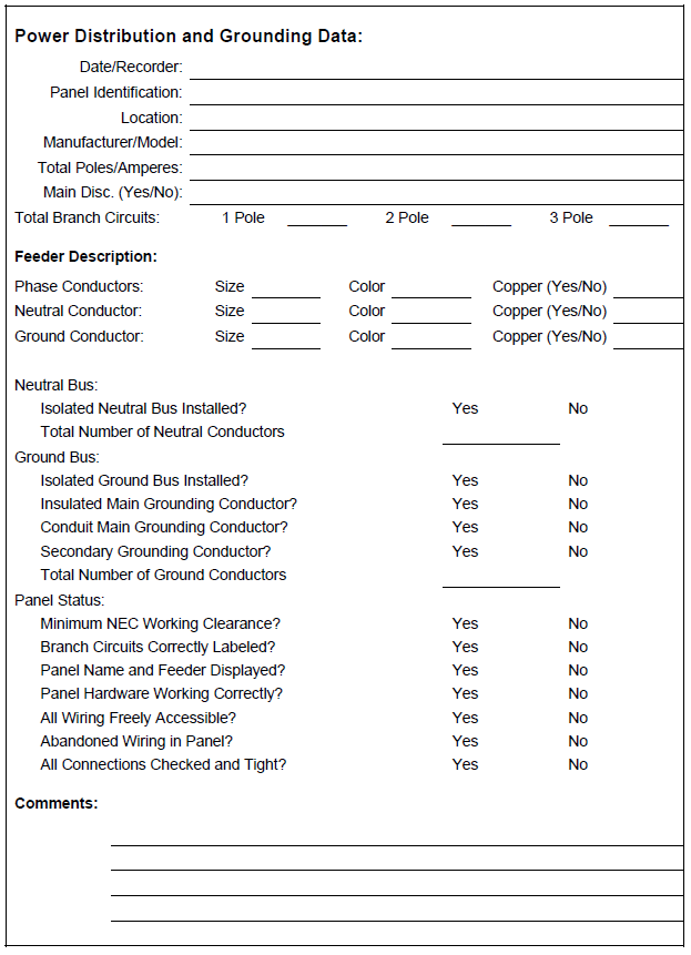
A data form that can be used for recording the power distribution and grounding information is provided in Figure 5.
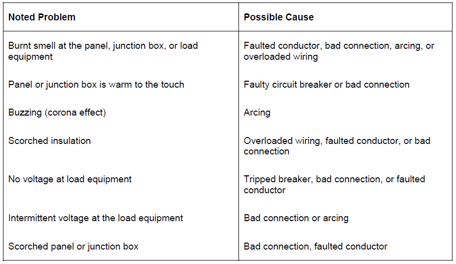
Problems with Conductors and Connectors
The first things to look for when inspecting the service entrance, panel boards, and equipment wiring during a site survey are problems with conductors or connections. A bad connection (faulty, loose, or resistive connection) will result in heating, possible arcing, and burning of insulation. Table 2 summarizes some of the wiring problems that can be uncovered during a site survey.
Table 2 – Problems with Conductors and Connectors
Missing Safety Ground
If the safety ground is missing, a fault in the equipment from the phase conductor to the enclosure results in line potential on the exposed surfaces of the equipment. No breakers will trip and a hazardous situation results.
Multiple Neutral to Ground Connections
Unless there is a separately derived system, the only neutral to ground bond should be at the service entrance. The neutral and ground should be kept separate at all panel boards and junction boxes. Double neutral-to-ground bonds result in parallel paths for the load return current where one of the paths becomes the ground circuit. This can cause misoperation of protective devices. In addition, during a fault condition, the fault current will split between the ground and the neutral that could prevent proper operation of protective devices (a serious safety concern). This is a direct violation of the NEC.
Ungrounded Equipment
Isolated grounds are sometimes used due to the perceived notion of obtaining a clean ground. Procedures which involve an illegal insulating bushing in the power source conduit and replacing the prescribed equipment grounding conductor with one to an Isolated Dedicated Computer Ground are dangerous, violate code, and are unlikely to solve noise problems.
Additional Ground Rods
Ground rods for a facility should be part of a grounding system, connected where all the building grounding electrodes are bonded together. Multiple ground rods can be bused together at the service entrance to reduce the overall ground resistance. Isolated grounds can be used for sensitive equipment, as described previously. However, these should not include isolated ground rods to establish a new ground reference for the equipment. The most important problem with additional ground rods is that they create additional paths for lightning stroke currents to flow. With the ground rod at the service entrance, any lightning stroke current reaching the facility goes to ground at the service entrance and the ground potential of the whole facility rises together. With additional ground rods, a portion of the lightning stroke current will flow on the building wiring to reach the additional ground rods. This creates a possible transient voltage problem for equipment and a possible overload problem for the conductors.
Ground Loops
Ground loops are one of the most important grounding problems in many commercial and industrial environments that include data processing and communication equipment. If two devices are grounded via different paths and a communication cable between the devices provides another ground connection between them, a ground loop results. Slightly different potentials in the two power system grounds can cause circulating currents in this ground loop. Because the communication signal levels can be quite low (e.g., five volts), very low magnitudes of circulating current can cause serious noise problems. The best solution to this problem is to use optical couplers in the communication lines, thereby eliminating the ground loop.
Insufficient Neutral Conductor
Switched-mode power supplies and fluorescent lighting with electronic ballasts are becoming increasingly prevalent in commercial facilities. The high harmonic currents produced by these loads can have a very important impact on the required neutral conductor rating for the supply circuits. The most important harmonic component in these load currents is the third. Third harmonic currents in a balanced system appear in the zero sequence circuit. This means that third harmonic currents from three single phase loads will add in the neutral, rather than cancel as is the case for the 60 Hz current. In typical commercial buildings with a diversity of switch-mode power supply loads, the neutral current is typically in the range 140%-170% of the fundamental frequency phase current magnitude. CBEMA has recognized this concern and has prepared a brief to alert the industry to problems caused by harmonics from computer power supplies.
Preparing an Audit Report
The result of a power quality audit is often a formal written report to a customer. The report may be as simple as a one or two page summary letter, or as detailed as a multi-section report. A standardized format for writing audit reports is recommended. In addition, since power quality is very technical and often confusing for a non-technical person, the report should be presented in easily understood language and organization. A suggested outline for an audit report includes the following sections:
− Executive Summary
• Description of the Problem
• Objectives of the Investigation
• Important Conclusions and Recommendations
− System Description
• Overview of the Utility Supply System
• Overview of the Customer System
− Engineering Analysis Summary
• Power Quality Concerns and Related Symptoms Evaluated in the Report
• Summary of Computer Simulation Results (if applicable)
• Mitigation Alternatives
• Economic Analysis (cost/benefit)
− Monitoring Results Summary
• Monitoring Period
• System Voltage Performance
• Summary Harmonic Distortion Levels
• Summary of Voltage Sags and Interruptions
• Summary of Transient Overvoltages
• Discussion of Major Events
− Appendices
• Glossary of Terms
The Executive Summary section should acknowledge that the utility or company is interested in helping the customer use electricity without problem, and is pleased to assist the customer in that pursuit. This section should provide a brief history of the events leading up to the audit work, and a description of all work that was done. Include any information that helps the reader understand the purpose and use of the audit report.
The Important Conclusions and Recommendations subsection may be organized by each conclusion drawn from the engineering and monitoring effort. In this structure, the rationale for each conclusion is stated and a specific recommendation is made. Each conclusion should state the cause of the problem, and its relative impact and importance to the customer. Recommendations should be described completely and leave no ambiguity about what actions should be undertaken.
The System Description section should include an overview of both the utility and customer systems, including all power system data collected during the investigation. Oneline or facility wiring diagrams should be included where appropriate.
The Engineering Analysis Summary section should present exactly what was found in each step of the diagnostic process. For example, what types of power quality problems or disturbances were found, and where. Include specific information to help the reader understand what was done. Photos and references to specific points on wiring diagrams or facility layouts are helpful. This section is also a good place to discuss the estimates made by facility personnel of the actual or estimated cost associated with each identified problem. This information is valuable in establishing a cost/benefit analysis for the customer and demonstrating the value of problem mitigation. This is particularly true if the solution to a specific problem involves the outlay of capital funds.
The Monitoring Results Summary section should include summary results for the relevant steady-state and disturbance quantities.
The Appendices section(s) should include supplemental information such as a glossary of terms and detailed monitoring results.
REFERENCES
IEEE Standard 1100. IEEE Recommended Practice for Powering and Grounding Sensitive Equipment (The Emerald Book).
IEEE Standard 1159. IEEE Recommended Practice on Monitoring Electric Power Quality.
ANSI/NFPA 70-1993, National Electrical Code.
Power Quality Considerations for Adjustable Speed Drives, EPRI Publication CU.3036.4.91, Electric Power Research Institute, 1991.
RELATED STANDARDS
IEEE Standard 1159
IEEE Standard 1346
IEEE Standard 1250
IEEE Standard 1036
IEEE Standard 519
GLOSSARY AND ACRONYMS
ASD: Adjustable-Speed Drive
CVT: Constant Voltage Transformer
GPR: Ground Potential Rise
IEEE: Institute of Electrical and Electronics Engineers
MOV: Metal Oxide Varistor
PWM: Pulse Width Modulation
TVSS: Transient Voltage Surge Suppressors
UPS: Uninterruptible Power Supply
