This Technical Paper Written by: Mark Stephens, P.E. Engineering Manager, EPRI PEAC Corporation, Semiconductor & Industrial PQ Group, EPRI PEAC Corporation, 942 Corridor Park Boulevard Knoxville, Tennessee 37932, Phone: (865)-218-8022, Fax: (865)-218-8001 mstephens@epri-peac.com, http://www.f47testing.com, June 13th, 2002
Introduction
The end of the report read…
“…Imagine a time in the not so distant future when the industry has embraced the proposed SEMI tool voltage sag immunity standard. As the lights blink in semiconductor manufacturing facility, the production tools will sail through the voltage sag without interruption. Realizing the enormous payback of the Task 24 effort, the semiconductor industry will save hundreds of millions of dollars every year in scrapped wafers and process downtime. If the proposed SEMI 2844 (later passed by as SEMI F47) standard is fervently adopted by this industry, the great chasm between today’s reality of overly sensitive tools and tomorrow’s dreams of system compatibility will be filled…”
Looking back on when I wrote this in February 1999, I still like the way I ended the EPRI Task 24 Report entitled “Power Quality in the Semiconductor Industry”. Maybe it was a overly dramatic, but it seemed to sum up what could happen if draft SEMI 2844 standard were passed by SEMI. In July of 1999, the dreams of those of us who had worked so hard on semiconductor power quality issues came to fruition – SEMI 2844 was passed at SEMICON West. SEMI issued the standard in September 1999 as “SEMI F47-0999: Provisional Specification for Semiconductor Processing Equipment Voltage Sag Immunity”. The first industry specific power quality standard was born. The standard was re-issued in February 2000 with minor modifications and the removal of the word “Provisional”. Developed in conjunction was a test methodology document entitled “SEMI F42: Test Methodology for Semiconductor Equipment Voltage Sag Immunity”. Originally based on EPRI PEAC’s own test plans, many contributed to the final revision of this document as well. There is no doubt that the passage of these two standards represents a major milestone for EPRI and for the power quality community. So, two years after the final versions of these standard were issued, is semiconductor equipment any more immune to voltage sags? To answer this, one must understand the basics of the standard, look at immunity results before the standard was implemented, and review the status of compliance now.
SEMI F47 Review
The SEMI F47 Specification for Semiconductor Processing Equipment Voltage Sag Immunity document defines the threshold that a semiconductor tool must operate without interruption (per SEMI E10) and it also provides a target for the facility and utility systems. Recognizing semiconductor factories require high levels of power quality due to the sensitivity of equipment and process controls and that recognizing semiconductor factories require high levels of power quality due to the sensitivity of equipment and process controls and that semiconductor processing equipment is especially vulnerable to voltage sags, SEMI F47 defines the voltage sag ride-through capability required for semiconductor processing, metrology, and automated test equipment.
The SEMI F47 document specifies the minimum voltage sag ride-through capability design requirements for equipment used in the semiconductor industry. The expected equipment performance capability is shown graphically on a chart representing voltage sag duration and percent deviation of equipment nominal voltage. The primary focus for this specification is semiconductor-processing equipment including but not limited to the following tool types:
- Etch equipment (Dry & Wet)
- Film deposition equipment (CVD & PVD)
- Thermal equipment
- Surface prep and clean
- Photolithography equipment (Stepper & Tracks)
- Chemical Mechanical Polishing equipment
- Ion Implant equipment
- Metrology equipment
- Automated test equipment
The actual SEMI F47 ride-through curve is shown below

The specification states that Semiconductor processing, metrology, and automated test equipment must be designed and built to conform to the voltage sag ride-through capability per the defined curve. Equipment must continue to operate without interrupt (per SEMI E10 – Standard for Definition and Measurement of Equipment Reliability, Availability, and Maintainability ) during single and two-phase voltage sag conditions identified in the area above the defined line. In the context of SEMI E-10, interrupt means any assist or failure. An assist is defined as an unplanned interruption that occurs during an equipment cycle where all three of the following conditions apply:
- The interrupted equipment cycle is resumed through external intervention (e.g., by an operator or user, either human or host computer).
- There is no replacement of a part, other than specified consumables.
- There is no further variation from specification of equipment operation.
Furthermore, a failure is any unplanned interruption or variance from the specifications of equipment operation other than assists. Although no variation in the tool’s process is the goal, this standard addresses these issues as related to the equipment operation only.
Pre-SEMI F47 Voltage Sag Immunity Issues
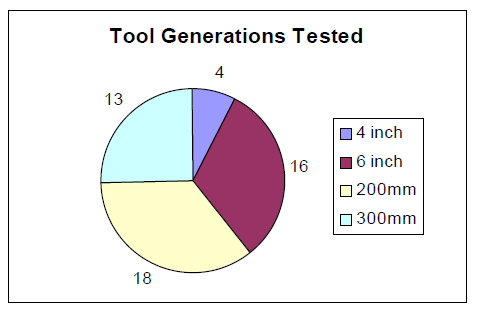
In order to initially characterize semiconductor tools to determine their sensitivity to voltage sags, EPRI PEAC’s custom engineering portable sag generator was used. Tests were conducted in semiconductor manufacturer clean rooms, at the tool supplier’s facility, or at the Power Quality Test Facility (PQTF), located in Knoxville, Tennessee. In all, 33 semiconductor tools were tested plus additional tests on tool subsystems such as robots, vacuum pumps and temperature control units [2]. The breakout of the technological generation of the tools that were tested is best indicated by the wafer size that is processed. In general, the larger the diameter of the wafer, the newer the technology. As shown in Table 1, the Task 24 efforts led to the testing of four generations of semiconductor tools technologies.
Table 1 Breakout of Semiconductor Tools tested by wafer size in Task 24 Project

As shown in figure 2, more tests were done on etcher tools than any other type of equipment. Although most all tool types tested exhibited susceptibility to voltage sags, the extensive number of tests done on etcher tools is a direct indication of their problematic nature during voltage sag events.

Using portable voltage sag test equipment developed by EPRI PEAC, the semiconductor tools were thoroughly characterized to understand their voltage sag susceptibilities. When examining the common “weak-links” found in semiconductor tools, many of the same mechanisms are responsible for across the board tool immunity problems. Table 3 displays the most common reasons for the shutdown of the tools that were tested and the percentage of the time that the particular “weak-link” was found to be a problem when the tool shutdown.
Table 3 Most Common Reasons for Voltage Sag Related Tool Shutdown for the First 33 Tools That Were Been Evaluated

A brief analysis of the power quality issues associated with each of these top six immunity issues follows.
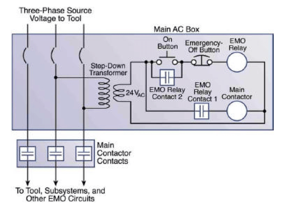
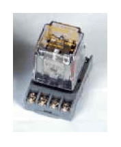
Ranked #1 – Emergency Machine Off (EMO) circuits. Comprised of a pilot relay and a main contactor, the EMO circuit is typically the most vulnerable part of a semiconductor tool in relation to the overall equipment voltage sag immunity. As shown in Table 3 the EMO circuit was found to be the shutdown mechanism 47 percent of the tests that were conducted. The EMO circuit is used to power up the tool through the main contactor. Typically driven by the smaller EMO pilot relay, the main contactor is used to apply power to the overall semiconductor tool. If either the EMO relay or main contactor are susceptible to voltage sags, the entire tool will shut down as a result. In the most sensitive circuits a small general-purpose clear plastic case relay (a.k.a “ice cube”) is used for the EMO relay. Research shows that sags as minor as 78 percent of nominal, lasting less than one-cycle in duration can shutdown an entire tool when these sensitive components are present. In contrast, other EMO circuits have been found to ride through voltage sags that are less than 50 percent of nominal voltage when robust relays and contactors are utilized in the design.
Ranked #2 – DC Power Supply Response. The second most common reason for tool susceptibility to voltage sags hinges on the lack of stored energy and/or the control scheme of DC power supplies. DC Power supplies used on semiconductor tools range from single-phase DC linear and switch-mode designs used to power user interface PCs, tool controllers, and instrument I/O applications. The voltage sag ride-through of most power supplies designed for these applications is directly related to the amount of stored energy and power requirement of the load. If one of these power supplies exhibits poor voltage sag ride-through, upsizing of the unit or utilizing one that can accept wide input voltage ranges can provide additional robustness.
Ranked #3 – 3-Phase Power Supplies. Semiconductor tools use a variety of 3-phase power supplies for high-voltage DC, microwave, and RF applications. In order to suppress arcing in the process chamber, many of these units are designed with little stored energy. For this reason some of these devices will shutdown when subjected to voltage sags. However, research has demonstrated that some of these units can continue to operate through the voltage sag event even though the output voltage may vary. Working closely with manufactures of these supplies, EPRI PEAC has learned that feasible changes can be made to make these units more robust.
Ranked #4 – Vacuum Pumps. Vacuum pumps are integral in the support of process chamber operations in many types of semiconductor tools. Closely coupled to the tool controller and EMO circuit operations, the entire tool is likely to shut down when the vacuum pump system is affected by a voltage sag event. In one test case, a chattering EMO contactor from the main AC box was found to cause the vacuum pump system shut down , leading to an interruption in the tool operation. However, most of the vacuum pump related voltage sag immunity issues were found to originate from the vacuum pump package control circuit. Often, the vacuum pump control circuits utilize several AC powered “ice cube” general purpose relays. In fact, one manufacturer utilizes twenty-seven such “weak” relays in their control scheme, fifteen of which directly interfaced with the tool controller.
Ranked #5 – Turbo Pumps. Typically powered from a single-phase source voltage, turbo pumps use magnetic-bearing technology to levitate the rotor on a magnetic field during highspeed turbine operation. The turbine turns at speeds up to 35,000 RPM. Previous generations of turbo molecular pumps used an AC motor and variable-frequency drive arrangement. To keep the rotor from crashing into the assembly during a power outage, a battery is used to keep the magnetic bearings energized until the rotor spun down. With a properly maintained battery the turbo-pump controller will survive outages lasting up to 2 seconds. If periodic battery replacement is not performed, the pump could be damaged during a power failure. During the voltage sag testing of etcher tools, EPRI PEAC witnessed poor ride-through in installed vacuum pump controllers due to improper battery pack maintenance. The newer generation of turbo molecular pumps, employ a DC motor and drive technology. A pulsed DC signal is used to rotate the field of a permanent-magnet motor. The kinetic inertia of the rotor acts as a motor generator to power the magnetic bearing levitation circuit until the rotor has come to a stop, thus eliminating the need for a battery.
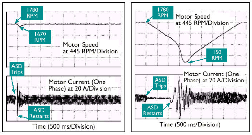
Ranked # 6 – AC Inverter Drives. AC inverter drives, often referred to as Adjustable Speed Drives (ASDs) are used in semiconductor tools range in sizes from fractional to about 10 horsepower. These ASDs are typically employed in blower applications to keep air circulating in high temperature processes applications. Most ASDs that are used for semiconductor tools allow the user to tune a set of parameters that govern the operation of the unit. Two common features are called Flying Restart and Kinetic Buffering. With these parameters enabled, many drives are able to ride-through voltage sags without the motor speed dropping significantly. The restart algorithm that determines the motor speed at which the ASD restarts varies from manufacturer to manufacturer. Some manufacturers have more efficient algorithms than others. Thus, one ASD model may afford smoother restarting than another. Figure 6 shows the motor speed during the shutdown and restart of two different ASD models (Model A and Model B) for a constant torque load. In both cases, motor speed slowed during the shutdown. However, the speed change of the motor connected to Model A was minimal, whereas the speed change of motor connected to Model B was significant. Before a semiconductor tool vendor purchases an ASD for a tool application, the user should consult with the ASD manufacturer to determine restart characteristics.
Post SEMI F47 Progress
Since January 1999, EPRI PEAC has continued to conduct voltage sag testing on Semiconductor tools. As of April 2002, EPRI PEAC has completed SEMI F47 tests on over 51 semiconductor tools, 14 subsystems, and over one hundred components. Furthermore, Semiconductor manufacturers have commissioned EPRI PEAC to perform audits of over 131 installed tools. This work has occurred in the United States, Asia, and Europe. In addition, other testing firms have entered the market to provide similar products and services. Based on this level activity, the SEMI F47 standard is being used as the yardstick in which to measure voltage sag performance.
In contrast to the utility funded tests conducted as a part of EPRI’s original Task 24 project, tool manufactures, wafer manufacturers, or component suppliers have funded the Post Task 24 tests. EPRI PEAC’s breakout of the total tools tested by type and wafer size is shown in Figures 7 and 8.

In order to better understand how well semiconductor equipment manufacturers are doing in their compliance efforts, Table 4 has been compiled. The table lists EPRI PEAC’s test number, the type of tool, whether SEMI F47 compliance was achieved, how it was achieved, and if the solution was designed in-house.
Table 4 Compliance History for Tools Evaluated by EPRI PEAC Following the Implementation of the SEMI F47 Standard

Table 4 Compliance History for Tools Evaluated by EPRI PEAC Following the Implementation of the SEMI F47 Standard
Key:
- 3-5kVA UPS on EMO and Sensitive Controls
- Embedded Solutions – Robust AC Contactors and Relays or DC Powered Units
- Batteryless Ride-Through Device on EMO circuit
- Batteryless Ride-Through Device on Tool Vacuum Pump Control circuit
- Batteryless Ride-Through Device on Tool Controller(s)
- Firmware Upgrade on Drive
- Robust Power Supplies
Several key statistics are of interest from Table 4:
1.The Percentage of Tool Manufacturers That Designed Their Compliance Solution without assistance was 20%. This indicates that tool manufactures still require help in understanding the requirements of SEMI F47 and designing their tools to meet the standard. EPRI PEAC is actively involved in working with tool suppliers in the design stage or to correct the problem during the compliance test
2.The Percentage of Tools Tested that were able to Pass SEMI F47 was 70%. This number is encouraging in that the majority of tool suppliers are able to meet the standard. None of the units that were certified utilized a power conditioner on the entire tool. Instead, a targeted approach with small single-phase power conditioners, embedded robust components, and/or firmware upgrades was utilized. In fact, roughly one-third of the tools that received SEMI F47 certification did so without any power conditioning.
3.Of those who were able to pass the test, 36% required a second round of testing of the modified tool design in order to achieve compliance. Since the SEMI F47 tests naturally uncovers areas of the tool that are vulnerable to voltage sags, the tool engineers and the power quality testing firm are often required to work together to develop a solution that can be evaluated at a later date. In many cases, the tool availability time can dictate whether further tests can be conducted at a given date.
4.About 3 in 8 (36%) of the tools that EPRI PEAC has certified to meet SEMI F47 have utilized a 3-5kVA UPS scheme. There is no doubt that the small UPS approach is not the most favored approach by the semiconductor manufacturers or the intention of the SEMI F47 standard. Section 1.3 of the SEMI F47 standard is explicit in this statement….
“It is the intent of this standard to provide specifications for semiconductor processing equipment that will lead to improved selection criteria for sub-components and improvements in equipment systems design. While it is recognized that in certain extreme cases or for specific functions battery storage devices may be appropriate, it is not the intent of this standard to increase the size or use of battery storage devices provided with equipment. Focus on improvements in equipment component and system design should lead to a reduction or elimination in the use of battery storage devices to achieve equipment reliability during volt-age sag events.”
In order to meet SEMI F47, a battery-based UPS is not required. Therefore, more work is needed to familiarize tool suppliers with the use of batteryless storage technologies. In fact, only one-in-four of the tools certified to meet SEMI F47 used batteryless ridethrough devices. Some manufactures still opt for a small UPS (500VA) for the tool workstation to keep from locking up or crashing the operating system in the event of a sever voltage sag or outage. Until technologies such as the Supercap or Ultracap are cheaply and readily available in a commercial UPS product, small battery based UPS systems are still likely to be used on the workstations.
5.The typical cost of the solution hardware required to make the tools that passed SEMI F47 compliant is $5,000 or less. This cost does not include the costs of engineering, compliance testing, consulting, and other associated costs. The solution usually involves either utilizing a power conditioner on the tools’ sensitive control circuits or replacing sensitive control elements with units that are certified to meet the standard.
SEMI F47 Compliance Strategies
The recommended strategies for achieving compliance presented here build on those that were recommended based on the findings from the Task 24 final report and conveyed by EPRI PEAC and other co-authors in a SEMATECH document entitled “Guide for the Design of Semiconductor Equipment to Meet Voltage Sag Immunity Standards”. The basic approach is to harden the small “weak-link” components to survive SEMI F47 voltage sag events. Effective strategies for improving a semiconductor tool’s voltage sag immunity and help the system meet SEMI F47 are:
- Use “Selective Power Conditioners” on susceptible loads
- Embed the Solution through proper design and component selection strategies
- Utilize a combination of both strategies [3].
Selective Power Conditioning
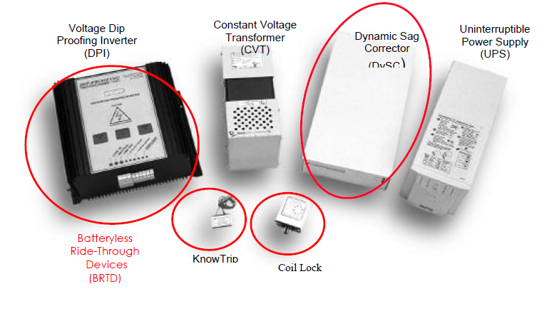
The use of selective power conditioning can lead to a great improvement in the overall tool’s robustness to voltage sags. The idea of this approach is to prop up the single phase powered “weak links” in the tool. The premise of this approach is that all equipment power users are not ultra-sensitive to voltage sags and thus do not need to be placed on conditioned power. The loads that are typically fed by selective power conditioning devices are single-phase devices with voltage requirements from 100Vac to 230Vac. Some of the most common selective power conditioning devices are shown in Figure 9.
The following is a discussion of the most common devices used for selective mitigation. Other products are available but are not discussed here due to the required brevity.
1.The Voltage Dip Proofing Inverter (DPI). The DPI falls into a class of device referred to as batteryless ride-through devices (BRTD). Since the DPI operates only when the voltage sag is detected (off-line technology) it only needs to be sized for the nominal load. The device basically continually rectifies incoming AC voltage to charge the DC bus capacitors. When a voltage sag is detected that drops below an adjustable threshold, the line to the incoming power to the device is opened and the DPI supplies a square-wave output to the load for about 1 to 3 seconds. Care should be taken when applying this solution in that not all loads are compatible with a square-wave output produced by the DPI. The same basic advice is also given when utilizing small UPS systems that produce a square-wave output. The amount of time that the load will be supplied can be calculated based on the real power and the energy storage of the particular DPI.
2.Constant Voltage Transformer (CVT). The CVT (a.k.a. ferroresonant transformer) is a ferroresonant transformer is a device that maintains two separate magnetic paths with limited coupling between them. The output contains a parallel resonant tank circuit and draws power from the primary to replace power delivered to the load. The transformer is designed so that the resonant path is in saturation while the other is not. As a result, a further change in the primary voltage will not translate into changes in the saturated secondary voltage, and voltage regulation results. These devices will allow for much better voltage sag ride-through if they are sized to at least two and a half the nominal VA requirement. Oversized in this manner, CVTs can supply a 100 percent of nominal voltage when the input voltage has dropped to as low as 40 percent of nominal.
3.The Uniterruptible Power Supply (UPS). The UPS can come in three basic types: Standby, Line-interactive, and Rectifier/Charger. The Standby UPS switches to a battery and provides an inverter output to the load once the voltage sag is detected. If the transfer is fast enough (< 1 cycle) and is in phase with the incoming voltage, typical control components are not likely to be affected by the sag event. Careful section of the this type of UPS is required in order to guarantee that sensitive control loads will not drop out before the unit switches to the inverter. The Line-Interactive UPS is an on-line type that employs a regulating transformer (CVT) when the incoming voltage is nominal. When a voltage sag is sensed, the unit then switches to the inverter to power the load. High inrush loads must be taken into account when using this unit since the CVT output can collapse from overloading. The Rectifier/Charger UPS is also an on On-line unit. The unit constantly rectifies the incoming AC line voltage. The resulting DC voltage is then used to charge the batteries and to feed the inverter circuit for the units output section. In the event of a voltage sag or outage, the unit switches to the battery for the source of the inverter’s power.
Ultimately, the determination of whether to use a UPS or some other voltage conditioning device depends on whether the load requires power during a brief outage and the end user’s willingness to perform periodic maintenance on the unit’s batteries.
4.The Dynamic Sag Corrector (DySC). The DySC system is a BRTD that corrects voltage sags down to 50 percent of nominal, supplying a sine-wave output. By drawing additional current from the input line (voltage sags above 50%) or from internal storage caps (voltage sags below 50%) the DySC maintains the output to the load. The smaller single-phase versions of this product are called the “MiniDysc” while the larger three-phase units are called “Pro DySC”. This product was developed in tandem with the SEMI F47 standard and is targeted specifically toward the semiconductor industry.
5.Coil Hold-In Devices. Coil hold-in devices are also BRTD that are designed to prop up individual relay and contactor loads . Two brands found on the market are the KnowTrip and the Coil Lock, neither of which are UL listed. These units are designed to mitigate the effects of voltage sags on individual relays and contactors. Typically, the coil hold in device is connected in line with the incoming control signal for the relay or contactor. Available for coil voltages of 120Vac, 230Vac, and 480Vac, the best application for this device is to prop up relays and contactors that are in an EMO, master control relay, or motor control center circuits. Costing less than eighty dollars, these units are very economical to support contactors and relays. Typical coil hold-in devices allow a relay or contactor to remain engaged until the voltage drops to around twenty-five percent of nominal. The unit installs between the relay or contactor coil connection terminals and the incoming AC control line.
A comparison on the Selective Power Conditioners discussed is shown in Table 5.
Table 5 Selective Power Conditioning Equipment Comparison

Embedded Solutions
In general, these solutions involve fixing the individual “weak links” components of a tool in order to increase the overall ride-through of the entire system. Embedded solutions are attractive since they in theory do not require add on power conditioning equipment, but instead involve using more robust or improved components in the tool design. Furthermore, semiconductor tool suppliers are more comfortable with this approach since it does not require the addition of unfamiliar technologies. The following guidelines for embedded solutions to meet SEMI F47 are discussed below:
No. 1 – Utilize SEMI F47 Compliant Relays and Contactors. Since SEMI F47 became a standard, control relays, safety relays, contactors, and motor starters have been certified as compliant with the standard.
No. 2 – Wire load devices in a phase-to-phase configuration where possible. This includes EMO transformers, power supplies, PCs and tool controllers. Connected in this manner, a single-phase drop to 50 percent of nominal equate to only 76 percent of nominal phase-to phase. Furthermore, if the load components on the secondary side of the transformer can survive voltage sags to 50 percent of nominal, they will not drop out even if one phase of the primary voltage drops to zero volts.
No. 3 – Avoid mismatched equipment voltages. If the equipment used in the tool design does not match the expected nominal input voltage, the tool will be more susceptible to voltage sags. This can occur when a transformer secondary voltages do not match the rated voltage for the connected equipment or a tool subsystem such as a servo controller or power supply is rated for a higher voltage (i.e. 240Vac equipment is used in a 208Vac). For relays and contactors, a mismatch of 10 percent of voltage equates to an increase in susceptibility by 10 percent. However, in DC power supplies, the energy stored in the internal capacitors can be as much as 18 percent lower when the input voltage is mismatched by a little as 10 percent – directly equating to a reduction in ride-through time.
No. 4 – Use universal input switching power supplies in every location possible, wired phase-to-phase. The universal input type power supply has a voltage range of 85 to 264Vac typically. When connected phase-to-phase in a 208Vac system (See No 2.), the power supply can continue to operate down to 41 percent of nominal. This type of supply should be specified for DC powered EMO circuit, tool DC power supplies, PCs, and tool controllers. Every Universal Input unit tested by EPRI PEAC Corporation has proven fully compliant when connected phase-to-phase.
No. 5 – Consider Circuit Breaker Characteristics. For a tool to be compliant with the SEMI F47 standard, circuit breakers and fuses should be selected to allow for higher inrush currents due to power quality variations within the SEMI F47 voltage sag range. This must be considered for constant power loads such as power supplies and variable frequency drives. Where possible, do not select breakers that have instantaneous trip characteristics.
No. 6 – Avoid the use of AC powered “ice cube” general purpose relays. Instead use a robust AC relay or utilize a DC power supply to power the EMO or control circuit configured as mentioned in guideline No. 4.
No. 7 – Do not use phase monitoring relays in the interlock circuit. These devices will easily trip during a voltage sag and can lead to tool shutdown. Instead utilize these devices to log that a voltage sag or phase problem exists. If the concern is that a motor might run in the wrong direction, interlock only with motor controls.
No. 8 – Utilize a non-volatile memory. This type of back-up technique for tool controllers ensures that the control system will not lose its place in the event of a voltage sag.
No. 9 – Do not overload DC power supplies. Since the amount of voltage sag ride-through time available from a DC power supply is directly related to the loading, DC power supplies should not be running at their maximum capacity. Oversizing by at least two times the expected load will help the power supply to ride-through voltage sags. This is only critical for systems that do not have a universal input front-end.
No. 10 – Use robust inverter drives. When using ac inverter drives in the tool design, specify units that have good voltage sag ride-through. Check with your drive supplier to make sure the drive firmware will support voltage sag ride-through. Flying restart, kinetic buffering, and the ability to have a low DC bus level trip point (50% of nominal is ideal) are essential. Be sure to configure the drive to take advantage of the features.
No. 11 – Consider Subsystem SEMI F47 performance. Make sure you consider your semiconductor tool subsystems during your design stage. If items such as vacuum pumps, cryopumps, or heat exchangers are not compliant to the SEMI F47 standard, the overall tool will not meet the standard as well.
No. 12 – Consider the Software and Control Program Issues. Your tool or system software developers should consider process variable fluctuations during voltage sags. It may essential that the bandwidth for certain process variables be widened or time filter delays be added avoid tripping of the process. The tool software developers should be part of your SEMI F47 compliance effort.
No. 13 – Consolidate Control Power Sources. When designing the layout of your tool control circuits, try to consolidate the control power feed such that they are fed from a common source or breaker where possible. If a small power conditioner is required to make the tool compliant to SEMI F47, this will make the implementation less painful.
No. 14 – Use a targeted voltage conditioning approach. As the last resort, apply only targeted voltage conditioning devices to prop up weak link components on the tool that cannot be retrofitted with comparable robust components.
Conclusion
Since the passage of SEMI F47, a flurry of activity has begun to harden semiconductor processing equipment to the standard. As a result, proactive component and voltage sag mitigation suppliers have stepped forth to have their products certified to the standard and/or integrated into tool solutions. From the perspective of the semiconductor manufacturers, the progress has not been fast enough in that many tools have not yet complied with the standard. Undoubtedly, an economy that has recently experienced a recession has played a major factor in the ability of some tool manufacturers to begin or complete SEMI F47 compliance efforts. However, based on the first two-years of implementation of SEMI F47, progress has been made in developing tools that are more robust to voltage sags. With assistance, tool vendors are beginning to understand the issues surrounding power quality and designing systems with voltage sags in mind. The SEMI F47 standard is a shining example of what an industry specific standard can accomplish. Furthermore, SEMI F47 serves as a testament that efforts in other industries such as food processing, metals, plastics, textiles, petrochemical, and pharmaceuticals should follow.
References
[1] SEMI F47-0200 “Specification for Semiconductor Processing Equipment Voltage Sag Immunity”, SEMI 2000
[2] EPRI Task 24 Final Report: Power Quality in the Semiconductor Industry, February 1999.
[3] “Guide for the Design of Semiconductor Equipment to Meet Voltage Sag Immunity Standards”, International SEMATECH Technology Transfer document 99063760B-TR, 1999.
EPRI PEAC Corporation
EPRI PEAC is the worldwide leader in Power Quality services for the Semiconductor industry – Offering training, compliance testing, design consulting, and on-site plant audits related to the SEMI F-47 Standard “Specification for Semiconductor Process Equipment Voltage Sag Immunity”. EPRI PEAC’s goal is to solve Semiconductor tool voltage sag susceptibilities for our manufacturer and tool supplier clients to enable compliance with the SEMI F47 Standard and maximize process uptime.
In 2000, EPRI PEAC Corporation established the PQ Starsm Program to test and certify manufacturer equipment per established power quality standards. PQ Starsm certification for the SEMI F47 standard (Specification for semiconductor Processing Equipment Voltage Sag Immunity) is available for semiconductor equipment suppliers. EPRI PEAC utilizes the SEMI F42 test standard (Test Method for Semiconductor Processing Equipment Voltage Sag Immunity). With the PQ Star certification, EPRI PEAC Corporation offers a third party verification that the equipment tested meets this important new power quality standard.
http://www.F47testing.com Technical Paper: Semiconductor Equipment Voltage Sag Immunity Improvements
