Published by Prof Jan Desmet, Hogeschool West-Vlaanderen, Email: jan.desmet@howest.be & Prof Angelo Baggini, Università di Bergamo, Email: angelo.baggini@unibg.it, June 2003
Source: Leonardo Power Quality Initiative (LPQI) Power Quality Application Guide Harmonics Neutral Sizing in Harmonic Rich Installations 3.5.1
Introduction
This section discusses the sizing of neutral conductors in the presence of power quality problems such as ‘triple-N’ – that is, currents with a harmonic order that is a multiple of three current harmonics. This issue is particularly important in low voltage systems where harmonic pollution by single phase loads is an increasingly serious problem. Triple-N harmonic currents add arithmetically in the neutral conductor rather then summing to zero as do balanced fundamental and other harmonic currents. The result is neutral currents that are often significantly higher, typically up to 170%, than the phase currents.
The sizing of conductors is governed by IEC Standard 60364, Part 5-52: Selection and Erection of Electrical Equipment – Wiring Systems. This Standard includes rules and recommendations for sizing conductors according to the current required by the load, the type of cable insulation and the installation method and conditions. Some normative rules are provided for sizing the neutral in the presence of harmonics, together with informative guidance in Annex D. National standards follow IEC 60364 closely but there is a significant time lag, so most national standards still do not deal with the neutral sizing issue in a comprehensive way. Since few installers and designers have easy access to the IEC standards, relying only on their national codes, they must depend on their own knowledge and experience when sizing neutral conductors. This application note is intended to clarify the issues involved and present the IEC guidance to a wider audience.
Theoretical background
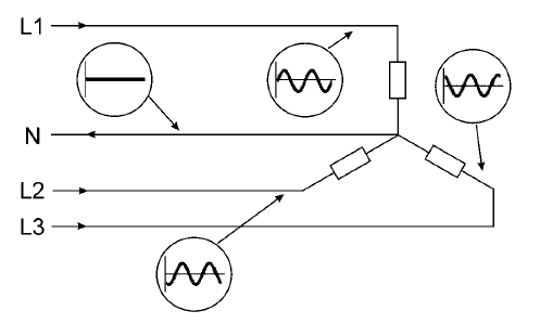
In a star-connected three-phase system, the current in the neutral conductor is the vector sum of the three line currents. With a balanced sinusoidal three-phase system of currents, this sum is zero at any point in time and the neutral current is therefore zero (Figure 1).
In a three-phase power system feeding linear single-phase loads the current in the neutral conductor is rarely zero because the load on each phase is different. Typically the difference is small and is in any case far lower than the line currents (Figure 2).

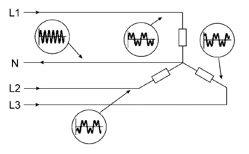
Where non-linear loads are being supplied, even when the load is well balanced across the phases, there is likely to be substantial current in the neutral conductor. With non sinusoidal currents, the sum of the three line currents, even with the same rms value, may be different from zero. For example, currents with equal rms values and square shape will result in a significant neutral current (Figure 3).
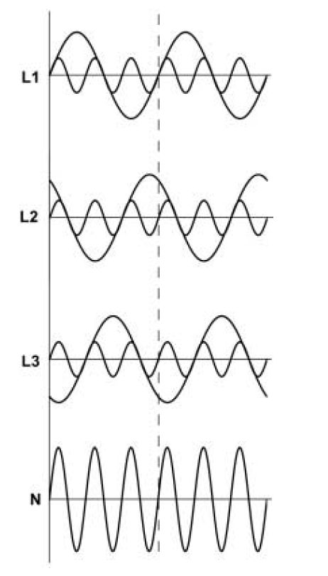
In fact, the third harmonic components (and all other harmonics where the order is a multiple of three – the sixth, ninth, etc.) of the line currents are all in phase with each other (i.e. they are homopolar components), so they sum arithmetically rather than cancelling by vector addition (see Figure 4).
The neutral current amplitude may exceed the phase current in amplitude at the supply frequency due to the third harmonic.
The requirements of the Standard
IEC 60364-5-52:2001, ‘Electrical Installations in Buildings – Part 5-52: Selection and Erection of Electrical Equipment – Wiring Systems’, is concerned with the safe installation of circuits from the point of view of installation techniques and conductor sizing. The installation method frequently affects the thermal conditions in which the cable operates and so affects the cable carrying capacity of the conductor or circuit. Where cables of several circuits are installed in the same conduit, trunk or void, the current carrying capacity of each cable is reduced because of the mutual heating effect. In other words, the current carrying capacity of a cable is determined by the amount of heat generated by the current flowing and the amount of heat that can be lost from the cable by convection. Together, these determine the working temperature of the cable which, of course, must not exceed that appropriate to the insulation material, 70 °C for thermoplastic insulation (such as PVC) or 90 °C for thermosetting insulation (such as XLPE). The ratings and adjustment factors given in the Standard are based on practical tests and theoretical calculations based on typical conditions and need to be modified in the light of known installation conditions. Since the presence of triple-N harmonics in the neutral conductor results in higher heat generation, cable size selection must make allowance for this.
Reference to sizing the neutral conductor in case of non-sinusoidal currents can be found in IEC 60364-5-524. Clause 524.2 indicates that the neutral conductor shall have at least the same section as the phase conductors:
- in two-conductor single-phase circuits and for all conductor cross-sections
- in multi-phase circuits and in three conductor single-phase1 circuits when the cross-section of the phase conductors is equal to or less than 16 mm2 for copper or 25 mm2 for aluminium.
1 i.e. a centre tapped single phase supply where the centre point is neutral.
Clause 524.3 states that, for other multi-phase circuits, the neutral conductor may have a reduced crosssection if all the following conditions are met:
- the maximum expected current, including harmonics, if any, in the neutral conductor during normal service is not greater than the current carrying capacity of the reduced cross sectional area of the neutral
- the neutral conductor is protected against overcurrent
- the size of the neutral is at least 16mm2 in copper or 25mm2 in aluminium.
These clauses are normative – in other words they provide regulations that must be followed in order to comply with the Standard. However, complying with these clauses requires knowledge of the type and number of loads that will be in use after the installation is put into service – unfortunately, this information is rarely available. The Standard also includes an informative annex – information provided to help the designer in the form of guidance and recommendation rather than regulation – that provides a methodology for sizing cables correctly.
This section presents this guidance with the addition of worked examples and some observations regarding de-rating in shared ducts and the effects of voltage drops.
Guidance from the Standard
The functioning of an electrical component or conductor can be significantly influenced by disturbances to the system, the supply, or the load. Of all of the electromagnetic disturbances that affect energy cables, the presence of current harmonics is one of the most important. The effects of this phenomenon can lead to overload of both phase and neutral conductors. Here, attention is focused on the sizing of the neutral conductor.
It should be noted that the current rating tables given in the Standard make many assumptions and it is the responsibility of the designer to recognise when these assumptions are not valid and make appropriate corrections. The most important assumption is that, in a four or five core cable, only three cores carry current; in other words, the load is assumed to be balanced and linear. In the situation where the load is unbalanced but linear the unbalance current flows in the neutral, but is offset by the fact that at least one phase conductor is carrying less load. Assuming that no phase conductor is overloaded, the total Joule loss in the cable is not excessive. When the load is non-linear there is a neutral current contributing to thermal loss as well as the full effect of the three line currents.
Under the conditions of current distortion described in paragraph 1.2, heat dissipation in the conductor due to the Joule effect is larger compared to the ideal linear load conditions, and the line capacity is therefore reduced. In addition, neutral conductors, often previously undersized with respect to the phase conductors in existing buildings (paragraph 1.3), can be overloaded even without the neutral current exceeding the rated phase current.
It is impossible to determine the neutral current in absolute terms unless the real or theoretical waveform of the load currents is known. However, as an approximation, the neutral current can be 1.61 times the phase current in the case of loads such as computers, but can reach the value of 1.73 times the phase current in the worst conditions with controlled rectifiers at high control angles, i.e. low DC voltages (α ≥ 60°).
The simplest way to solve the problem is to apply appropriate corrective coefficients to the cable current carrying capacity. Annex D of IEC Standard 60364-5-52 also gives a methodology for determining the appropriate derating factor. For simplicity, the approach assumes that:
- the system is three-phase and balanced
- the only significant harmonic not being cancelled in the neutral is the third one (i.e. the other triple-N harmonics have relatively low magnitudes and other harmonics are approximately balanced and sum to zero) and,
- the cable is 4 or 5 core with a neutral core of the same material the same cross-section as the phase conductors.
In the strictest sense, calculation of the current harmonic effects should also take account of skin effect, which will reduce capacity as a function of the conductor size but, as a first approximation, it can be neglected.
Table 1 shows the recommended reduction factors.
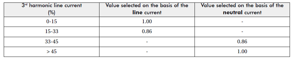
To calculate the capacity of a cable with four or five conductors where the current in the neutral conductor is due to harmonics, multiply the standard current carrying capacity of the cable by the correction factor.
For phase currents containing 15% or less triple-N harmonics, the standard does not suggest any increase in neutral cross-section. Under these circumstances, the neutral current might be expected to be up to 45% of the phase current, and an increase of about 6% in heat generation compared to the normal cable rating. This excess is normally tolerable except in situations where the cable is installed in areas with poor ventilation or where there are other sources of heat nearby. An additional safety margin may be desirable in, for example, confined spaces.
For phase currents containing 15% to 33% triple-N components, the neutral current may be expected to be similar to the phase current and the cable must be de-rated by a factor of 0.86. In other words, for a current of 20 A, a cable capable of carrying 24 A would be selected.
Where the triple-N component of the phase currents exceeds 33% the cable rating should be determined based on the neutral current. For phase currents containing from 33% up to 45% triple-N harmonics, the cable size is determined by the neutral current, but de-rated by a factor of 0.86. At 45% triple-N current the cable is rated for the neutral current, i.e.135% of the phase current, derated by 0.86.
For even higher triple-N components, for example the typical worst case of 57%, the cable size is determined solely by the neutral current. There is no need for a correction factor because the phase conductors are now oversized.
Since the data for the reduction factors has been calculated on the basis of the third harmonic current value only, higher order triple-N harmonics at a higher level than 10% would further reduce the acceptable current. The situation described can be particularly critical when the neutral is used in common by several circuits (where this is permitted by local regulation).
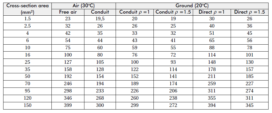
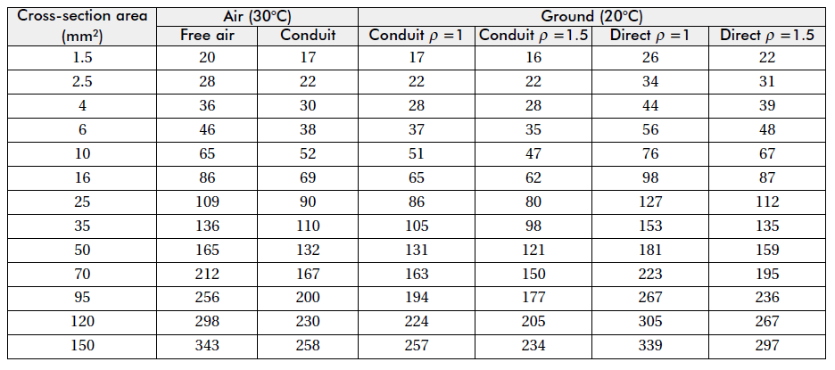
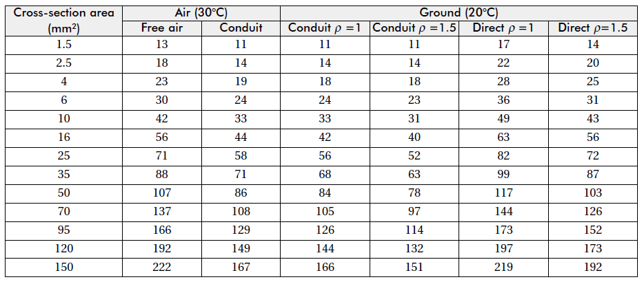
Tables 2 to 5 show how the current rating changes with and without 3rd harmonic currents. The current ratings are calculated according to the IEC 60364-5-523 Standard. The ratings listed are for a 4 core 0.6/1kV cable with thermosetting (90 °C) insulation.
When using single core cables the choice of the neutral and phase conductor cross sections becomes independent. On the other hand the mutual thermal interaction is more difficult to model analytically because of the varying relative positions.
The most direct way to proceed is independent sizing of the neutral conductor, always bearing in mind that the thermal performance and the reactance of the circuit depends on the relative positions of the conductors. Additional factors that should be taken into account include:
- When the cable is grouped with other cables, the greater current flowing in it (i.e. the harmonic current in the neutral) produces more heat so there is an effect on other cables. This must be taken into account by using enhanced grouping factors.

- The voltage drop in the neutral caused by all triple-N harmonics becomes harmonic voltage distortions on all phases of the supply. This may require a further increase in neutral cross-section for long cable runs.
Particular attention has to be given to armoured or metal-screened cables. The contribution of harmonics to eddy currents in the screen or armour may be considerable. Therefore, whenever a load current distortion is expected, the neutral conductor should never have a cross-section smaller than the corresponding phase conductors. The same holds, of course, for all accessories of the neutral circuit.
When the design dimensions of the neutral circuit increases beyond that of the corresponding phase components, as can happen even in standard electrical systems, it is difficult if not impossible to find suitable commercial components available that are capable of correctly integrating into the system. The only suitable alternative is to limit the load or to size for the largest cross-section. Protection should, of course, be sized correctly for the smaller cross-section of the phase conductor.
For final circuits, separate neutrals for each line and separate circuits for each distorting load should be planned. This also ensures the best possible electromagnetic independence among both disturbing and susceptible elements. The use of the best possible balance of the loads avoids further contributions to the neutral current due to unbalance. The above considerations are just as important and applicable for large cross-section cables as they are to modest cross-section cables. They can also be applied, at least as a good approximation level, to busbars.
Numerical example
Consider the following example: a three-phase circuit with a 39 A load rating to be installed using a 4-core PVC (70 °C) insulated cable laid directly onto the wall. In the absence of harmonics, it is common practice to use a copper conductor cable with a 6 mm2 cross-section with a capacity of 41 A.
With 20% of the third harmonic, applying a 0.86 reduction factor, the equivalent load current is:
39.0 / 0.86 = 45 A
for which a cable with a 10mm2 cross-section would be necessary.
With a third harmonic equal to 40%, the cable section should be chosen according to the neutral current equal to:
39 × 0.4 ×3 = 46.8 A
and applying a 0.86 reduction factor a rated current:
46.8 / 0.86 = 54.4 A
so a cable with a 10 mm2 section is also suitable for this load. With 50% of third harmonic, the cable section to be chosen still depends on the neutral current:
39 × 0.5 × 3 = 58.5 A
requiring a 16 mm2 cable. (In this case the reduction factor is equal to 1.)
Conclusions
The discussion in this paper has pointed out how common design solutions, valid without power quality problems, become meaningless when the theoretical hypotheses upon which they are based are not fulfilled. In this instance, the assumption that voltages and currents have ideal waveforms is not valid.
In the case of neutral conductor sizing, common ‘old’ practice would advise the choice of a cross-sectional area smaller or equal to that of the corresponding phase conductors and the use of a scheme with the neutral shared among more lines. On the other hand, a correct consideration of the electromagnetic effects occurring with non-linear loads requires the selection of a neutral conductor with a cross-section larger than, or equal to, that of the corresponding phase conductors and based on the real current that is flowing in it. The use of a separate neutral conductor for each line (previously mandatory in some countries) is also required. The numerical example shows that the problem can arise on both important sections of a plant and on the final circuits of any electrical system.
References
[1] P Chizzolini, P L Noferi: Ottimizzazione degli interventi sulla rete di distribuzione mirati al miglioramento della continuita’ del servizio elettrico. LXXXVII Riunione AEI, Firenze 1986.
[2] N Korponay, R Minkner: Analysis of the new IEC drafts for 185 (44-1) and 186 (44-2) instruments transformers in relation to the requirements of modern protection systems – Journée d’ études: Les transformateurs de mesure E2-20 SEE novembre 1989.
[3] T M Gruzs: “A survey of neutral currents in three-phase computer power systems”, IEEE Transaction on industry applications, vol. 26, n° 4 July/August 1990.
[4] IEC 364-5-52 – Electrical Installations in Buildings – Part 5-52: Selection and Erection of Electrical Equipment – Wiring Systems.
