Published by Antonio Ardito, Stefano Malgarotti, Angelo Schiappacasse,1
1 This paper was developed within the activity Ricerca di Sistema DM 26/01/2000. Authors are with CESI spa, via Rubattino 54, 20134 Milano (MI), Italy, (e-mail: malgarotti@cesi.it, tel. +39-02 2125-5517)
ABSTRACT
Power Quality is of concern in both open market and in vertically integrated environment, since the quality of the energy supply is on one side a prerequisite to establish a market, and, on the other side, needed to support the investments for industries requiring an acceptable power supply quality, due to their sensible production processes.
Power Quality issue deals with both “continuity of supply” and “voltage quality”. Normally the standard levels of the electric power supply are defined by the competent National Authority, that has to define the indices of continuity of supply and the relevant standard levels. The assessment of the actual power quality levels has to be performed both for network areas, to which a set of Client/Users are connected, and for specific Client/Users, in their point of common coupling with the public network. The final scope is not only to assess the actual power supply quality, but to stimulate its improvement, through technical provisions related to investments. The paper, making use of CESI experience, deals with power quality rules and indices applied or under development, with the possible methods to assess the actual power supply quality, even by measurements, and with the technical provisions to be taken in the sub-transmission and distribution network in order to improve the power quality.
These provisions consist of network reinforcements, improvement of network schemes, enhancement of relay protection system, change in the neutral earthing practice, adoption of power electronic devices (Custom Power), enhancement of insulation co-ordination with reference mainly to lightning performance and to the adoption of suitable surge arresters.
1.INTRODUCTION TO EMC AND POWER QUALITY
The matter of Electromagnetic Compatibility (EMC) has been developed over a long period of time and it is rather complicated because it covers conducted and radiated phenomena over the whole frequency spectrum in use (from 0 to 400GHz), excluding problems related to telecommunications like the allocation of frequencies, transmission techniques and other specialised subjects. In Europe a strong impulse to the development of the EMC subject has been given by the European Union (EU) Directives 85/374 and 89/336 [1], [2]; in any case it is not yet complete from the point of view of the practical application which still has unfulfilled requirements.
Power Quality is conventionally intended as the quality of the electric power supply to customers/users in terms of technical characteristics that have to comply with levels fixed or recommended by standards, rules and contractual obligations: EMC standards cover Power Quality.
With the purpose to provide a self-contained description concerning the EMC subject, some basic definitions are given here under:
Electromagnetic disturbance: any electromagnetic phenomenon, which may degrade the performance of a device, equipment or system or adversely affect living or inert matter. (An electromagnetic disturbance may be an electromagnetic noise, an unwanted signal or a change in the propagation medium itself);
Disturbance level: the value of a given electromagnetic disturbance, measured in a specified way. (Disturbance levels are generally designated as 95 % probability values on a basis of a time statistics);
Electromagnetic Compatibility (EMC): the ability of an equipment or system to function satisfactorily in its electromagnetic environment and without introducing intolerable electromagnetic disturbances to anything in that environment;
Electromagnetic Compatibility Level: the specified disturbance level at which an electromagnetic compatibility should exist. (The compatibility levels are reference values for purpose of coordinating emission and mainly immunity of equipment; they are generally designated as 95 % probability values on a basis of time and system locations statistics);
Planning level: The specified disturbance level used mainly for planning purposes in evaluating the impact on the system of all disturbing consumers or equipment.
(Planning levels are:
- internal reference values of the utilities, generally
equal to or lower than compatibility levels, - not standardized, but only indicative values, often used for emission co-ordination in determining the emission allowed to the consumers, generally designated as 95 % probability values on a basis of a time statistics);
Total disturbance level: the level of a given electromagnetic disturbance caused by the superposition of the emissions of all pieces of equipment in a given system (Total disturbance levels are generally designated as 95 % probability values on a basis of a time statistics);
Conducted disturbance: Electromagnetic phenomen which propagates along the electricity supply conductors and/or signal-control connections. In transmission and distribution systems conducted disturbances can propagate along power lines and in some cases across
transformers so that they may affect equipment distant from their source. The main types of conducted disturbances are harmonics, interharmonics, voltage fluctuations, voltage dips and short supply interruptions, voltage unbalance, mains frequency variation;
Emission level: level of a disturbance injected into the surrounding space or into the supply conductors (Emission levels are generally designated as 99% or 95 % probability values on a basis of a time statistics);
Immunity level: the maximum level of a given electromagnetic disturbance, incident in a specified way on a particular device, equipment or system, at which no degradation of its specified performance occurs;
Susceptibility: the inability of a device, equipment, or system to function without degradation of its specified performance in the presence of an electromagnetic disturbance.
Utilities are concerned particularly with the electromagnetic disturbances which are described as “conducted disturbances”. These are so called because they are carried by the power conductors and are in this way distinct from other disturbances, like those consisting
of electromagnetic fields affecting the space around their sources.
Table 1 : Conducted Disturbances
| Conducted low Frequency Phenomena | Harmonics, Interharmonics Voltage fluctuations/flicker Voltage unbalance Voltage dips and interruptions Signalling systems Power frequency variations Induced low frequency voltages Direct Current in AC networks |
| Conducted high frequency phenomena | Unidirectional transients Oscillatory transients Magnetic fields |
2.INTERACTION BETWEEN PARTIES
The distributors are the operators of a network which is provided for the sole purpose of delivering an electricity supply to the consumers, but which unintentionally on their part becomes the medium on which electromagnetic disturbances are conducted from their sources to susceptible equipment. In fact, particularly for low frequency conducted disturbances that are prone to summing up together, the disturbances at the supply terminals are the result of a population of sources spread along the network; practically the distribution network becomes a collector of disturbances mainly generated by consumers and conveys them to the sensitive equipment. Often distributors are concerned with large installations (Users) which may be the source of significant levels of disturbance emission.
It is mandatory, and usually is a condition of supply, that these emissions be maintained below levels which, in combination with emissions from all other sources, would interfere unduly with the performance of other users’ equipment. It is generally necessary, therefore, to set down specific emission limits for each large User on the basis of connection regulations; a strict co-operation between electric utility and consumer is often necessary. Distributors are also concerned with an increasingly large proportion of conducted disturbances that have their source in the section of the environment described as residential, commercial and light industry. As the equipment in this environment is comprised of large numbers of individually small items, the only feasible way to promote electromagnetic compatibility is to ensure that the design of the equipment is such that disturbance emissions are adequately controlled, having regard to the additive effect of emissions from multiple sources and to the adequate equipment immunity to disturbances. This implies that appropriate standards for both emission and immunity are adopted.
On the basis of what above reported, compliance with EMC requirement in distribution networks implies an interaction between several parties as:
- Standardization bodies (environment definition, immunity and emission of single equipment)
- Supply utilities (rules for connection of the installation with disturbing loads)
- Users in collaboration with designers of plants and equipment manufacturers (choice of equipment and mitigation methods if required).
Figure 1 taken from [3], shows the relationships and the mutual effects between the standardisation process, the supply system and the user installation.

Figure 1: Relation between standardization, management of voltage characteristics, user equipment and installation options [3]
3.INTERNATIONAL STANDARDS RELEVANT TO POWER QUALITY
3.1 CENELEC standards relevant to the voltage characteristics of electricity supply
In the European Union (EU), with the goal to create a wide economic space without barriers to internal trade, a number of Directives have been issued by the Commission of the EU, to remove the differences in the legislation of the Member States, which could affect the free exchange of goods and services.
In particular the EU, recognising the energy market as an important component of the internal market, issued two Directives: Directive 85/374 EEC of July 25, 1985 on Product Liability [1], states in Article 2 that electricity is to be considered a product and, as a consequence, its characteristics have to be defined; Directive 89/336 EEC of May 2, 1989 on Electromagnetic Compatibility [2], declares that the Member States are responsible for ensuring that electricity distribution networks are protected from electromagnetic disturbances, which can also affect the connected equipment. An amendment introduced by Directive 92/31 has extended the transitory period to the end of 1995. On mandate of European Commission, CENELEC2 has been charged to develop a standard relevant to the voltage characteristics of electricity supplied by low and medium voltage public distribution systems. The mandate specified the different aspects to be covered, which were exclusively related to the following characteristics of the supply voltage: frequency, magnitude, waveform and symmetry of the three-phase-voltages.
The standard prepared by CENELEC is the EN 50160: “Voltage characteristics of electricity supplied by public distribution systems”, Second Edition, March 2000, [4]. The Scope of EN 50160 specifically excludes compatibility levels or emission limits. Its sole function is to give values for the main voltage characteristics of electricity supplied by LV and MV public networks.
The standard is applicable only under normal operating conditions of the supply system, excluding any condition outside the supplier’s control.
On the basis of IEC3 Standards, compatibility levels can be exceeded with a 5% probability in time and also in locations of the supply network, while voltage characteristics can be not complied with for 5% of the time in a specified observation period, but in all locations of the network. This explains why some of the EN 50160 voltage characteristics are less stringent than the compatibility levels.
Moreover the voltage characteristics serve as a reference concerning the electricity supply, as an indication on its expected performance and as a guiding criterion for selecting the immunity of user equipment.
2 European Committee for Electrotechnical Standardization
3 International Electrotechnical Commission
3.2 Standards relevant to compatibility level
Rules and recommendations presently in force and dealing with EMC compatibility levels for public networks are:
- IEC 61000-2-2 (Standard);
- IEC 61000-3-6 (Technical Report) and IEC 61000-3-7 (Technical Report).
- UNIPEDE “Report on EMC co-ordination in electricity supply systems”.
IEC 61000-2-2 Standard sets the compatibility levels for LV public supply networks with reference to harmonics, interharmonics, flicker, unbalance. Voltage dips and short interruption are dealt with by a statistical approach without setting limit values. The compatibility levels for MV and HV are under development.
IEC 61000-3-6 and IEC 61000-3-7 Technical Reports outline principles dealing with requirements for connecting large distorting loads to MV and HV public power systems. Both documents report the compatibility levels in LV and MV systems and the planning levels in MV, HV and EHV systems. The first document is relevant to harmonic voltages while the second one is relevant to flicker and rapid voltage changes.
UNIPEDE4 “Report on EMC co-ordination in electricity supply systems” deals with the co-ordination of the emission of low frequency conducted disturbances in public electricity supply systems with reference to harmonics, interharmonics, flicker and unbalance.
4.THE ROLE OF SUPPLY UTILITIES AND USERS
EMC requirement for conducted disturbances in distribution networks mainly consists in:
• emissions from each separate source of disturbance are such that the combined emissions from all sources do not exceed the conventionally accepted level of disturbance to be expected in the environment;
• equipment immunity is such that the appropriate level of performance at the conventionally expected level of disturbance is assured.
What above implies, from one side, to control the total disturbance in the distribution networks by connection, regulation and emission standards and, from another side, to adopt immunity level of the equipment assuring a margin with respect to the total disturbance level expected at the supply terminals.
4 International Union of Producers and Distributors of Electrical Energy
Figure 2, taken from [3], shows the relationships of the different above mentioned levels in the perspective of EMC co-ordination in a deterministic representation.

Figure 2: Deterministic representation of the co-ordination of conducted disturbances.
(1): Defined by Standards or Electricity Supplier (time statistic, 95% value)
(2): For a network location with a medium-high disturbance
(3): Defined by Electricity Supplier (time statistics, 95% value)
(4): Defined by Standards (time and location statistics, 95% value)
(5): Defined by Standards (time statistics, 95% value)
(6): Defined by Standards or agreed between User and Manufacturer
On the basis of what reported above, in EMC coordination relevant to the conducted disturbances, the roles of utilities and users can be very synthetically summarised as follows:
• Utilities have to control the total disturbance levels in the different system stages (different voltage levels), assuring the respect of the compatibility levels on the LV; this by defining reasonable and flexible disturbance emission limits for the users. In other words utilities have to assure that the supplied voltage at the user terminals presents characteristics being inside predefined ranges.
• Users have to respect emission limits and to adopt suitable immunity levels for equipment and machinery (including mitigation methods if required).
5. LOW FREQUENCY CONDUCTED DISTURBANCES
In this paper only the following types of low frequency conducted disturbances are considered: flicker; voltage dips; long and short interruptions; harmonics [4]. Flicker: a voltage fluctuation that causes changes of luminance of lamps giving unsteadiness of visual sensation. The flicker intensity is evaluated by UIE – IEC flicker measuring method through the following indices: Short Term Severity (Pst) measured over a period of 10 min; Long Term Severity (Plt) calculated from a sequence of 12 Pst values according to the following expression:

Voltage dips: a sudden reduction of the supply voltage to a value between 90% and 1% of the declared voltage followed by a voltage recovery in a short period of time;
Supply interruption: when the voltage at the supply terminal is lower than 1% of the declared voltage:
- Long interruption – duration > 3min;
- Short interruption – duration <3min and >1s;
Harmonic voltage: a sinusoidal voltage with a frequency equal to an integer multiple of the fundamental frequency.
Regarding the voltage levels of the systems, if not specifically stated, the following definitions apply:
- Low Voltage (LV): VN ≤1kV
- Medium Voltage (MV): 1kV<VN ≤35kV
- High Voltage (HV): 35kV<VN≤230kV
- Extra High Voltage (EHV): 230kV<VN
A short list of planning and compatibility levels from international standards is reported here under.
5.1 EHV and HV planning levels
Harmonics

Total harmonic distortion:

where Vh is the voltage amplitude of h harmonic order and Vl is the rms value of the fundamental frequency voltage. During each period of one week, the 95% of the 10 minutes rms values of each individual harmonic voltage (Vh) has to be equal or lower than the values in the previous table.
Flicker

5.2 MV planning and compatibility levels
Harmonics

Total harmonic distortion:

where the meaning of quantities and symbols is the same as in point 5.1.
Flicker

Supply voltage dips and interruptions

5.3 LV compatibility levels
Harmonics
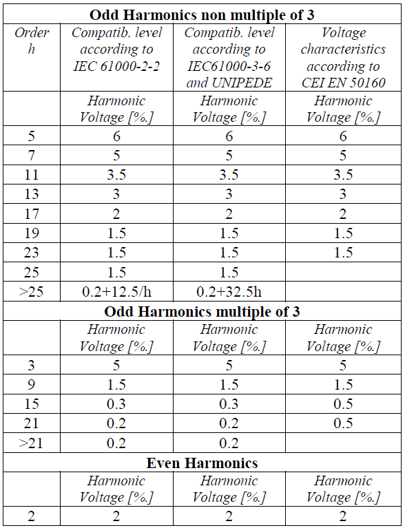

Total harmonic distortion:

where the meaning of quantities and symbols is the same as in point 5.1.
Flicker

Supply voltage dips and interruptions

6.RULES ON CONTINUITY OF SUPPLY IN ITALY
In Italy the standard levels of quality of the electric power supply are defined by the competent Authority. Nowadays the Authority has already defined the indices of continuity of supply and some relevant standard levels, while, as far as the voltage quality is concerned, the Authority charged the Italian Independent System Operator (GRTN) to issue technical rules, now under elaboration, covering this specific aspect. Continuity of supply is defined as the absence of interruption of electric energy supply to the Users.
The aims of the Authority are:
- to define an exhaustive and homogeneous method to detect the interruptions;
- to define a method to record and store the above data, that have to be traceable and truthful;
- to stimulate the improvement of the continuity of supply, making it nearer to the one of other Countries that nowadays show higher performance;
- to reduce the differences in the continuity of supply among various Italian regions and areas;
- to introduce an automatic mechanism for refunding the Users, when the standard levels are not fulfilled.
The distribution utility has the duty to set up and fill a data-base of the interruptions to its Users. The definition and classification of the interruptions are the following:
- Interruption is the condition when the voltage, in the point of common coupling, becomes <1% of the nominal voltage, according to international standards.
- The interruption is defined as prearranged when it is scheduled and noticed to the User:
- 1 day in advance, at least;
- through suitable means;
- with indication of the starting time and duration.
- The accidental interruptions (i.e. without notice) are classified as:
- long, when the duration is > 3 min;
- short, when the duration is < 3 min and >1 s;
- transitory, when the duration is < 1s.
- The Distribution utility has to detect and record all the interruptions: the prearranged ones and the accidental ones (long, short and transitory). Each record has to report the origin, the cause (only for accidental long interruptions), the number of HV and MV Users affected, the number of LV Users affected (limited to short and long interruptions only), the timing of the progressive restoration of the supply. The two indicators relevant to the continuity of supply are:
- the number N of interruptions per User, for all kind of interruptions;
- the cumulative duration D of the interruptions per User (limited to prearranged and accidental long interruptions only).
- The Distribution utility has to calculate the values of the above indicators:
- for each HV User (for all kind of interruption);
- for each MV User (limited to prearranged and accidental long interruptions only);
- the average value for both MV User (for all kind of interruption) and LV User (limited to prearranged and accidental long interruptions and short interruptions only).
Depending on the population of the municipality, different standard levels (thresholds) of the D indicator for LV User are already fixed, limited to accidental long interruptions:
- highly populated municipality (>50.000 inhabitants): D = 30 min;
- medium populated municipality (>5.000 and <50.000 inhabitants): D = 45 min;
- lowly populated municipality (<5.000 inhabitants): D = 60 min.
For all other indices, the standard levels (thresholds) are not yet fixed.
7.POWER QUALITY IMPROVEMENT
As far as rural or semi-rural distribution systems are concerned, both continuity of supply and voltage quality are significantly affected by lightning. In fact such systems have typically overhead lines that are exposed to direct and indirect lightning which causes common mode overvoltages (i.e. between live conductors and ground). Such overvoltages produce insulation failures, thus causing transitory and short interruptions, or even long lasting ones when they cause damages to equipment; on the other side, they causes impulse overvoltages towards the users.
Electric utilities are making a big effort in order to improve the power quality with respect to this kind of phenomena, mainly with regard to the continuity of supply, that is the most sensitive issue. Different remedies have been investigated and then adopted.
Some utilities are substituting spark gaps by metal-oxide surge arresters on medium voltage systems in order to better protect transformers and other equipment, thus reducing the number of long (permanent) interruptions. However, even the arresters are not very effective to protect line insulation: they are ineffective against the lighting strokes that directly hit the line, while, as regards overvoltages induced by indirect lightning strokes that hit the ground near the line, arresters are able to protect a very short length close to themselves, due to the short time to crest of the induced overvoltages.
In particular, with regard to the Italian MV overhead line distribution network, the percentage of interruptions correlated to lightning is estimated between 25% and 30%, with higher values for the permanent ones. The comprehensive gain in terms of reduction of interruptions by replacing spark gaps by surge arresters is roughly estimated between 4% (for lines equipped with rigid pin insulators) and 7 % (for lines equipped with cap and pin insulators).
As far as the overvoltages transferred from the medium voltage to the low voltage network and thus to the LV users are concerned, a typical provision consists in the grounding of the LV system neutral not at the transformer itself, i.e. near the grounding of the MV surge arresters, but better at some distance, i.e. at the first LV line pole. As regards the state of the neutral of the medium voltage networks, now in Italy, as in other countries, electric utilities are turning to the resonant earthed neutral system due to many advantages, among which an expected improvement of the power quality to the users.
This provision, in fact, enables a reduction of the number of interruptions thanks to a higher extinction probability of single-phase to ground arcing fault. Beyond this main advantage, a decrease of permanent faults is expected due to a lower stress on MV equipment and mainly cables; this is a direct consequence of a lower fault current and a lower transient recovery voltage at fault extinction.
Shunt breakers, that are connected between each phase and ground at MV bus-bar, are used in MV isolated neutral systems from a long time and they prove to be very effective in clearing the single-phase transient fault before the switching of the main line breaker, but their main drawback lies in a higher stress on the insulation of the sound phases, thus sometimes causing a double phase-to-ground fault (“cross-country”) evolution.
Another very promising provision that is widely used in advanced countries and that is going to be applied in Italy too, consists in the use of line reclosers installed along the MV lines, that enable a fast recognition and clearing of the faulted line section between two subsequent reclosers, thus avoiding the switching of the feeder breaker in the station. This provision in practice allows a reduction of the line length switched off to clear the fault (and thus of customers involved).
The mitigation of the main disturbances affecting the distribution network and the connected loads, can be obtained by applying Power Electronic Devices. More precisely, the present available devices can be divided into the following main categories:
- traditional devices – UPS (Uninterruptible Power Supply);
- innovative devices, named “CUSTOM POWER”.
As regards this last category, various kinds of devices are applied in order to fulfil different functions:
- Improvement of the supply power quality to susceptible loads;
- Mitigation of the impact of disturbing loads on the distribution network;
- Voltage control and reactive power and power factor (cos ϕ) compensation in weak distribution networks ;
- Active power peak shaving.
These devices are applied mainly to MV distribution networks by now, and their rated power ranges from hundreds kVA up to few tens MVA. For LV applications the rated power reaches few hundreds kVA. A list of typical “Custom Power” devices with their main features and functions is reported here below

8.REFERENCES
[1] EUROPEAN UNION, “Council Directive 85/374 on the approximation of the laws of the Member States relating to the liability for defective products”, Official Journal (07.08.1985)
[2] EUROPEAN UNION, “Council Directive 89/336 on the approximation of the laws of the Member States relating to electromagnetic compatibility”, Official Journal, (23.05.1989)
[3] UNIPEDE – NORMCOM, Application Guide to the European standard EN 50160 on “Voltage characteristics of electricity supplied by public distribution systems”, C. Mirra, December 1994
[4] EN 50160, Second Edition, 2000-03 Voltage characteristics of electricity supplied by public distribution systems
[5] Report on EMC coordination in electricity supply systems UNIPEDE 1994
[6] IEC/TR3 61000-3-6, First Edition, 1996-10 – Assesment of emission limits for distorting loads in MV and HV power systems.
[7] IEC/TR3 61000-3-7, First Edition, 1996-10 – Assesment of emission limits for fluctuating loads in MV and HV power systems.
[8] UIE, Disturbances Working Group: Connection of fluctuating loads C. Mirra, 1988
[9] IEC Publ. 61000-2-2, 1990 and future second edition (at present
IEC 77A/324/CDV, 2000-09-29) : “Electromagnetic Compatibility (EMC). Part 2: Environment. Section 2: Compatibility levels for low-frequency conducted disturbances and signalling in public low voltage power supply systems”
[10] IEC Publ. 61000-3-3: “Electromagnetic Compatibility (EMC).- Part 3: Limits – Section 3: Limitation of voltage fluctuations and flicker in low-voltage supply systems for equipment with rated current ≤16 A per phase”, (December 1994)
[11] IEC 61000-4-15, First Edition, 1997–11. “Electromagnetic Compatibility (EMC).- Part 4: testing and measurement techniques- Section 15: Flickermeter – Functional and design specifications
[12] “Definition of the physical characteristics of electrical energy supplied by low and medium voltage public systems” – UIE Disturbances WG Connection of fluctuating loads; UNIPEDE DISNORM 10.
[13] J. Douglas: “Custom Power: Optimizing Distribution Services”, Epri Journal May/June 1996
[14] N.G. Hingorani: “Overview of Custom Power Applications”, IEEE Summer Meeting, San Diego (USA), 1998
[15] Cigrè SC 14 – WG 14.19: “Static Synchronous Compensator (STATCOM)”, Brochure Cigrè n° 144, August 1999
[16] I. Iyoda, M. Takeda, G.F. Reed: “Improved Power Quality Solutions Using Advanced Solid-State Switching and Static Compensation Technologies ”, IEEE Paper 0-7803-4893-1/99,
1999
[17] A. Sundaram et alii: “Custom Power: The Utility Solution ”, Cired 1995, Report 5.09
[18] L. Borgard: “Grid Voltage Support”, Transmission & Distribution World, October 1999
[19] R. Kenner: “Distribution System Static Var Compensator: Field
Experience”, IEEE Winter Meeting, Technical Panel Session of IEEE WG P1409, San Diego (USA), 1998
[20] K. Chan et alii: “Innovative Solutions for Power Quality Enhancement”, CIRED ’99, Nice (France)
[21] N.H. Woodley, L. Morgan, A. Sundaram: “Experience with an Inverter Based Dynamic Voltage Restorer”, PE–796–PWRD–0– 06-1997
[22] N.H. Woodley: “DVR Field Experience 0.6 to 6 MVA Systems”, Siemens presentation to the Technical Panel Session of IEEE WG P1409, New Orleans (USA), April 1999
