Published by Henryk Markiewicz, Email: henryk.markiewicz@pwr.wroc.pl, & Antoni Klajn, Email: antoni.klajn@pwr.wroc.pl, Wroclaw University of Technology, July 2004. Website: www.pwr.wroc.pl
Source: Leonardo Power Quality Initiative (LPQI) Power Quality Application Guide Voltage Disturbances 5.4.2 Standard EN 50160
Introduction
Electrical energy is a product and, like any other product, should satisfy the proper quality requirements. If electrical equipment is to operate correctly, it requires electrical energy to be supplied at a voltage that is within a specified range around the rated value. A significant part of the equipment in use today, especially electronic and computer devices, requires good power quality (PQ). However, the same equipment often causes distortion of the voltage supply in the installation, because of its non-linear characteristics, i.e. it draws a non-sinusoidal current with a sinusoidal supply voltage (see Section 3.1 of this Guide). Thus, maintaining satisfactory PQ is a joint responsibility for the supplier and the electricity user. According to standard EN 50160 [1] the supplier is the party who provides electricity via a public distribution system, and the user or customer is the purchaser of electricity from a supplier. The user is entitled to receive a suitable quality of power from the supplier. In practice the level of PQ is a compromise between user and supplier. Where the available PQ is not sufficient for the user’s needs, PQ improvement measures will be needed and will be the subject of a cost-benefit analysis (see Section 2.5 of this Guide). However, the cost of poor PQ usually exceeds the cost of measures required for improvement – it is estimated that losses caused by poor power quality cost EU industry and commerce about € 10 billion per annum (see Section 2.1 of this Guide).
However, electrical energy is a very specific product. The possibility for storing electricity in any significant quantity is very limited so it is consumed at the instant it is generated. Measurement and evaluation of the quality of the supplied power has to be made at the instant of its consumption. The measurement of PQ is complex, since the supplier and user, whose sensitive electrical equipment is also a source of disturbances, have different perspectives.
Standard IEC 038 [2] distinguishes two different voltages in electrical networks and installations:
- supply voltage, which is the line-to-line or line-to-neutral voltage at the point of common coupling, i.e. main supplying point of installation
- utility voltage, which is the line-to-line or line-to-neutral voltage at the plug or terminal of the electrical device.
The main document dealing with requirements concerning the supplier’s side is standard EN 50160, which characterises voltage parameters of electrical energy in public distribution systems. This is a European standard but it is supplemented in some regions or countries by other supplemental standards, such as [3] in Germany, or [4] in Poland. Many regional codes, such as the German TAB [3] apply to an individual utility, but these are being unified as part of the liberalisation of the German electricity market. According to IEC 038, both standard EN 50160 and rules [3,4] concern the supply voltage, i.e. that measured at the point of common coupling.
On the user’s side, it is the quality of power available to the user’s equipment that is important. Correct equipment operation requires the level of electromagnetic influence on equipment to be maintained below certain limits. Equipment is influenced by disturbances on the supply and by other equipment in the installation, as well as itself influencing the supply. These problems are summarised in the EN 61000 series of EMC standards, in which limits of conducted disturbances are characterised. Equipment sensitivity to utility voltage quality, as well as mitigation measures, are presented in Section 3 (Harmonics) and Section 5 (Voltage Disturbances) of this Guide.
The subject of this section is a detailed presentation of standard EN 50160 and an analysis of its requirements according to the operation of chosen equipment. Methods of measuring supply voltage parameters are also presented.
Basic definitions of voltage parameters
In standard EN 50160 several voltage parameters are defined. The most important are:
Supply voltage – the rms value of the voltage at a given moment at the point of common coupling, measured over a given time interval.
Nominal voltage of the system (Un) – the voltage by which a system is designated or identified and to which certain operating characteristics are referred.
Declared supply voltage (Uc) – is normally the nominal voltage Un of the system. If, by agreement between the supplier and the user, a voltage different from the nominal voltage is applied to the terminal, then this voltage is the declared supply voltage Uc.
Normal operating condition – the condition of meeting load demand, system switching and clearing faults by automatic system protection in the absence of exceptional conditions due to external influences or major events.
Voltage variation – is an increase or decrease of voltage, due to variation of the total load of the distribution system or a part of it.
Flicker – impression of unsteadiness of visual sensation induced by a light stimulus, the luminance or spectral distribution of which fluctuates with time.
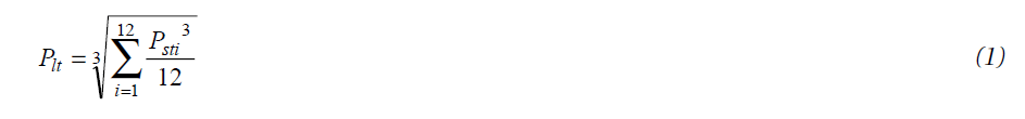
Flicker severity – intensity of flicker annoyance defined by the UIE-IEC flicker measuring method and evaluated by the following quantities:
- Short term severity (Pst) measured over a period of ten minutes
- Long term severity (Plt) calculated from a sequence of 12 Pst – values over a two-hour interval, according to the following expression:
Supply voltage dip – a sudden reduction of the supply voltage to a value between 90% and 1% of the declared voltage Uc, followed by a voltage recovery after a short period of time. Conventionally the duration of a voltage dip is between 10 ms and 1 minute. The depth of a voltage dip is defined as the difference between the minimum rms voltage during the voltage dip and the declared voltage. Voltage changes which do not reduce the supply voltage to less than 90% of the declared voltage Uc are not considered to be dips.
Supply interruption – is a condition in which the voltage at the supply terminals is lower than 1% of the declared voltage Uc. A supply interruption is classified as:
- prearranged in order to allow the execution of scheduled works on the distribution system, when consumers are informed in advance
- accidental, caused by permanent (a long interruption) or transient (a short interruption) faults, mostly related to external events, equipment failures or interference.
Temporary power frequency overvoltages – have relatively long duration, usually of a few power frequency periods, and originate mainly from switching operations or faults, e.g. sudden load reduction, or disconnection of short circuits.
Transient overvoltages – are oscillatory or non-oscillatory, highly damped, short overvoltages with a duration of a few milliseconds or less, originating from lightning or some switching operations, for example at switch-off of an inductive current.
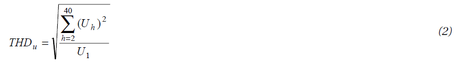
Harmonic voltage – a sinusoidal voltage with a frequency equal to an integer multiple of the fundamental frequency of the supply voltage. Harmonic voltages can be evaluated:
- individually by their relative amplitude Uh related to the fundamental voltage U1, where h is the order of the harmonic
- globally, usually by the total harmonic distortion factor THDU, calculated using the following expression:
Interharmonic voltage – is a sinusoidal voltage with frequency between the harmonics, i.e. the frequency is not an integer multiple of the fundamental.
Voltage unbalance – is a condition where the rms value of the phase voltages or the phase angles between consecutive phases in a three-phase system are not equal.
Main requirements of EN 50160
EN 50160 gives the main voltage parameters and their permissible deviation ranges at the customer’s point of common coupling in public low voltage (LV) and medium voltage (MV) electricity distribution systems, under normal operating conditions. In this context, LV means that the phase to phase nominal rms voltage does not exceed 1000 V and MV means that the phase-to-phase nominal rms value is between 1 kV and 35 kV.
The comparison of the EN 50160 requirements with those of the EMC standards EN 61000, listed in Tables 1 and 2, show significant differences in various parameters. There are two main reasons for these differences:
◆ The EMC standards concern the utility voltage, according to IEC 038, while EN 50160 deals with the supply voltage. The differences between these voltages are due to voltage drops in the installation and disturbances originating from the network and from other equipment supplied from the installation. Because of this, in many standards of the EN 61000 series the equipment current is an important parameter, while the load current is not relevant to EN 50160.
◆ EN 50160 gives only general limits, which are technically and economically possible for the supplier to maintain in public distribution systems. When more rigorous conditions are required, a separate, detailed agreement between supplier and consumer must be negotiated. Measures for improving PQ imply additional cost and equipment and are considered in other parts of this Guide.
◆ EN 50160 has additional limitations. It does not apply under abnormal operating conditions, including the following:
- conditions arising as a result of a fault or a temporary supply condition
- in the event of the failure of a customer’s installation or equipment to comply with the relevant standards or with the technical requirements for the connection of loads
- in the event of the failure of a generator installation to comply with relevant standards or with the technical requirements for interconnection with an electricity distribution system
- in exceptional situations outside the electricity supplier’s control, in particular:
- exceptional weather conditions and other natural disasters
- third party interference
- actions of public authorities
- industrial action (subject to legal requirements)
- force majeure
- power shortages resulting from external events.
As the analysis of parameters presented in Table 1 shows, these requirements are not particularly rigorous for the supplier. The numerous situations in which the standard does not apply can excuse the majority of outages and voltage disturbance events that occur in practice. Thus, many suppliers interpret the requirements of EN 50160 as principally informative and accept no responsibility when the limits are exceeded.

Table 1 – Comparison of supply voltage requirements according to EN 50160 and the EMC standards EN 61000
On the other hand, the consumer’s point of view is usually totally different – they regard the limits given in EN 50160 as requirements that must be guaranteed by the supplier. However, as mentioned before, for many consumers, even fulfilling the requirements given in EN 50160 does not assure a satisfactory level of PQ. In such cases the level of PQ required must be defined in a separate agreement between supplier and consumer.

Table 2 – Values of individual harmonic voltages at the supply terminals for orders up to 25, given in percent of Un
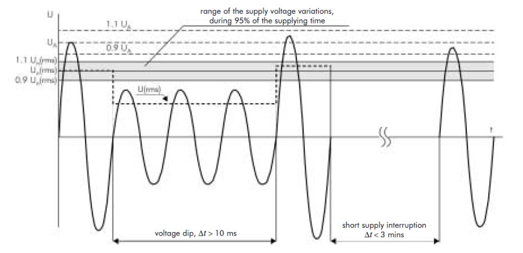
Figure 1 – Illustration of a voltage dip and a short supply interruption, classified according to EN 50160; Un – nominal voltage of the supply system (rms), UA – amplitude of the supply voltage, U(rms) – the actual rms value of the supply voltage
Operation of equipment and requirements of EN 50160
The correct operation of electrical equipment requires a supply voltage that is as close as possible to the rated voltage. Even relatively small deviations from the rated value can cause sub-optimal operation of equipment, e.g. operation at reduced efficiency, or higher power consumption with additional losses and shorter service life. Sometimes prolonged deviations can cause operation of protection devices, resulting in outages. Of course, the correct operation of equipment also depends on many other factors, such as environmental conditions and proper selection and installation.
Investigation of the independent influence of each supply voltage parameter on equipment operation is easily performed, but when parameters vary simultaneously the situation is much more complex. In some cases, after detailed analysis of the effects of each of the different voltage parameters, results can be superimposed in order to estimate the total influence of many parameters. The influence of a particular voltage parameter on equipment operation is made based on mathematical formulae describing analysed physical phenomena. Two simple examples, concerning lighting and motors, follow.
For incandescent light sources, supply voltage is the most significant influence on the luminous flux, as illustrated in Figure 2 and formula (3). The permissible supply voltage variations according to EN 50160 can thus cause significant changes of the flux. EN 50160 allows, for example, that the supply voltage can be equal to Un-10 % or Un+10% for a long period, thus an incandescent lamp will deliver as little as 70%, or as much as 140%, of its nominal luminous flux respectively. Furthermore, at Un +10%, the service life of these lamps is reduced to about 25% of the nominal value (Figure 3), i.e. about 250 hours instead of the typical life of 1 000 hours. (Note that the durability of fluorescent and discharge lamps depends mainly on the number of turn-on cycles. The effect of supply variations is small.) The values shown in Figures 2 and 3 are calculated for steady state operation voltage at the given value.
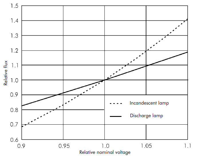
Figure 2 – Relative value of luminous flux F of an incandescent and discharge lamp as a function of the supply voltage according to formula (3)

Figure 3 – Relative value of the service life (durability) of an incandescent lamp as a function of the supply voltage according to formula (4)
In practice the voltage value changes continuously according to the operation and load conditions in the network, as for example shown in Figure 4. The mathematical description of characteristics shown in Figures 2 and 3 are:

where:
- F = luminous flux
- U = supply voltage
- Fn = luminous flux at nominal value of supply voltage Un
- b = factor equal 3.6 for incandescent lamps and 1.8 for discharge lamps
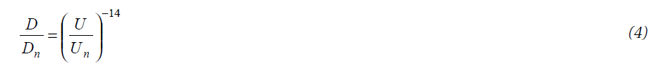
where:
- D = service life (durability) of the incandescent lamp
- Dn = durability at nominal value of supply voltage Un.

Figure 4 – Examples of voltage dips (rms phase to neutral voltage); oscillograms showing the supply voltage (upper trace) and frequency changes (lower trace) at the PCC of a small factory
One can see that the requirements concerning voltage changes in EN 50160 are not very rigorous. Even keeping voltage variations in the permissible limit ±10%, can cause under performance of lighting sources In practice, these variations should be limited to about ±(3-4)%, in order to avoid negative consequences in lighting.
The voltage fluctuations shown in Figure 4 illustrate the voltage influence on the flicker severity, which can be measured and calculated according to formula (1). Measurement of flicker is considered in another section of the Guide.
For electric motors the most significant factor is the fluctuation of torque, which depends on the square of the supply voltage value. Problems could occur during start-up of heavy loads, because the inrush current causes an additional voltage drop within the installation (Figure 5). In practice, for the majority of three phase electric motors, start-up occurs normally at or above 85% of nominal voltage for heavy starting loads and at or above 70% for light starting loads. Thus, the EN 50160 voltage fluctuation requirements are satisfactory here. However prolonged operation of the motor at an rms voltage value of –10% or +10 % of Un can cause other negative consequences: overloading and operation of the thermal protection in the first case, or operation at excessive power and protection tripping in the second case. All voltage dips can cause nuisance tripping of the motor protection.
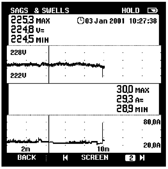
Figure 5 – Example of supply voltage changes (upper trace) at start-up of an asynchronous motor; lower trace – load current in the supplied installation of a small factory; the peak at the end of current flow is the inrush process
The influence of the load current on the supply voltage in the installation depends on the impedance of the supply grid. The utilization voltage at the equipment depends on the impedance of the supply grid and that of the customer’s installation. An illustration of the influence of load current on the supply voltage is shown in Figure 6.

Figure 6 – Illustration of the load current influence on the supply voltage dips in the electrical installation
Other important problems for the motors are voltage harmonics in and unbalance of the supply voltage. Voltage unbalance in a three-phase system causes an opposing torque, proportional to the negative sequence voltage component. Each voltage harmonic produces a respective harmonic current and its own torque, which can be coherent or opposite to the main torque, for various slip values. The most important here are the 5th and 7th harmonics. Figure 7 illustrates a case in which the 7th harmonic torque can cause problems during motor start-up, where the characteristic torque and the braking torque curves cross.

Figure 7 – Influence of asynchronous torque produced by harmonics on the main torque characteristic of an asynchronous motor
For other electrical equipment the relationship between supply voltage and its power or efficiency may be significant. For the majority of equipment, voltage changes in the range (0.9 – 1.1) Un do not cause any negative consequences, especially for common heating devices. For equipment with a higher sensitivity to the supply voltage proper protection should be installed.
Measuring methods
Measurement and testing of supply voltage quality, according to EN 50160, requires specialised apparatus and measuring methods (see Sections 3.2 and 5.2 of this Guide). This arrangement enables continuous monitoring, over 7 days, of the following parameters:
- voltage in three phases
- frequency
- total harmonic distortion factor THDU
- voltage unbalance factor, which is a multiple of positive and negative sequence voltage components
- fast and slow voltage variations, which are defined as short term (Pst) and long term (Pst) flicker severity factors (equation 1).
This type of equipment also enables measurement of voltage dips and outages, its frequency and duration.
The measured parameters are processed and recorded as 10 minute time-segments (1008 segments over 7 days). For each segment the mean value of the measured parameter is calculated. After the 7-day recording period a so-called “ordered diagram” is produced, which shows the sum of the duration of a given distortion level in the observed time period. (For frequency measurement, the duration of each single segment is 10 seconds).
An example of an ordered diagram is shown in Figure 8. It clearly shows whether the measured voltage parameters have been maintained at the permissible level for 95% of the tested time. (Table 1).
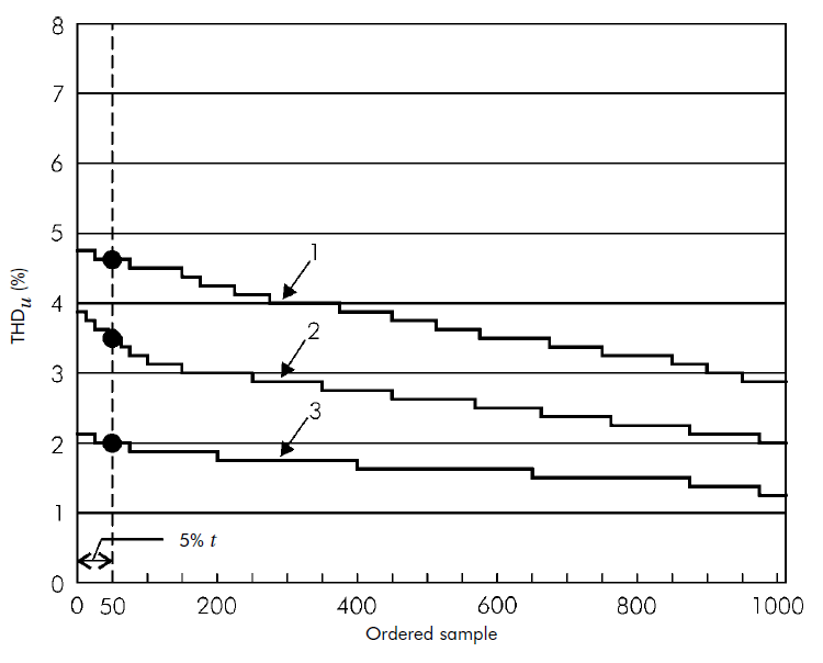
Figure 8 – Example of the ordered diagram of the total harmonic distortion factor measured in substations supplying low voltage industrial (1 and 3) and municipal (2) networks
Country perspectives
As mentioned above, while EN 50160 gives general limits for public supply networks, various European countries have additional rules governing supply conditions. Many of these national regulations cover areas not included in EN 50160, such as the maximum permissible harmonic load to be connected to the PCC.
The German national standard VDE 0100 states that the voltage parameters defined in DIN EN 50160 reflect extreme situations in the network and are not representative of typical conditions. In planning networks, the recommendations of VDE 0100 should be followed. One of the TABs [3] gives maximum values (per unit) for phase-angle controlled resistive loads (1 700 VA single-phase, 3 300 VA two-phase and 5 000 VA balanced three-phase) and for uncontrolled rectifier loads with capacitive smoothing (300 VA single-phase, 600 VA two-phase and 1000 VA balanced three-phase). The equipment standard VDE 0838 (EN 60555) is also quoted.
In Poland, the rules of electrical energy distribution established by the government [4] give the fundamental parameters of the supply voltage (Table 3) and do not refer to EN 50160. Additionally, consumers are divided into six groups, for which separate, permissible total annual outage times are defined. The document also deals in detail with various economic aspects of the energy market, principles of settlement between network and distribution companies etc.
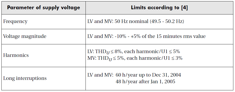
Table 3 – Requirements concerning PQ of supply voltage in Polish distribution network, according to [4]
In Italy there is an important document dealing with the continuity of supplied supply [8]. The Italian Regulatory Authority for Electricity and Gas (AEEG) has in fact set out a uniform system of service continuity indicators and has put in place a system of incentives and penalties in order to progressively bring continuity levels up to meet European standards. The Authority has divided the national territory into 230 geographical zones, sub-divided by areas of population density and has set improvement targets for each area on the basis of the previous year’s performance. Utilities that succeed in improving by more than the required rate can recover the higher costs sustained. Conversely, companies have to pay a penalty if they fail to meet the improvement target. Interruptions due to acts of God, or those caused by third parties, are not included in the calculation. The overall performance target is to bring continuity levels up to national benchmark levels based on European standards: 30 minutes of interruptions overall per user per year in large cities (high density); 45 minutes in medium-sized towns (medium density): and 60 minutes in rural areas (low density). Other countries have similar regimes imposed by the regulatory authorities.
The UK has a number of documents making up the distribution code. One of the most important is G5/4, discussed elsewhere in this Guide, which regulates the connection of harmonic loads to the point of common coupling. Measures to encourage the improvement of continuity are the responsibility of the Office of Gas and Electricity Markets (OFGEM).
Conclusions
The requirements of EN 50160 are not difficult for electricity suppliers to fulfil. The parameters of the supply voltage shall be within the specified range (Table 1) during 95% of the test period, while the permitted deviations in the remaining 5% of the period are much greater. For example, the mean value during 95% of the time shall be between 90% and 110% of the nominal voltage. This means that, in an extreme case, customers could be supplied at 90% of nominal voltage continuously while, for 5% of the time, the voltage could be much lower. If, in such a boundary situation, other parameters are also at the extremes permitted in the standard, for example harmonic voltages or voltage unbalance, then equipment mal-operation is likely.
The standard could be improved. For example, requiring the mean values of measured voltage parameters, over the whole of the test period within ±5% would guarantee that the supply voltage could not be maintained at the lower or upper boundary value for a prolonged period.
The number of voltage dips permitted (up to 1 000 during the year) and the number of short and long outages are rather high from the customer’s point of view. Voltage dips to below 30% of the nominal voltage with duration longer than 0.3 s can cause low voltage protection to trip or contactors in the motor circuits to drop out. Thus, the real number of process interruptions will be much greater than the number that would be expected to result from voltage interruptions.
EN 50160 should be understood as representing a compromise between supplier and customer. It requires that the supplier provide, as a minimum, a barely adequate quality supply. Most suppliers routinely exceed these requirements by a large margin, but do not guarantee to do so. If the customer has higher requirements, mitigation measures should be provided or a separate agreement for a higher quality supply must be negotiated. However, the important advantage of the standard is:
- definition of the voltage parameters important for power quality
- uantitative determination of the values, which are a reference point in evaluation of the power quality.
It is the task of the electricity regulator to set a level of quality that requires best practice from the supplier, while not setting the level too high so that the price of electricity increases for everybody.
References and Bibliography
[1] EN 50160, Voltage characteristics of electricity supplied by public distribution systems, 1999
[2] IEC 038, IEC standard voltages, 1999
[3] Technische Anschlussbedingungen (Technical requirements of connection), VDEW
[4] Rozporzadzenie Ministra Gospodarki z dnia 25 wrzesnia 2000, w sprawie szczególowych warunków przylaczania podmiotów do sieci elektroenergetycznych, obrotu energia elektryczna, swiadczenia uslug przesylowych, ruchu sieciowego i eksploatacji sieci oraz standardów jakosciowych obslugi odbiorców. Dziennik Ustaw Nr 85, poz. 957 (Rules of detailed conditions of connection of consumers to the electrical power network and quality requirements in Poland).
[5] Baranecki A et al, Poprawa jakosci zasilania w sieciach NN i SN. (Improvement of supply quality in LV and MV networks), Elektronizacja 1-2/2001
[6] Seipp G G, Elektrische Installationstechnik, Berlin – München, Siemens AG, 1993
[7] DIN VDE 0100-100 (VDE 0100 part 100): 2002-08
[8] Decision 128/1999: Definizione di obblighi di registrazione delle interruzioni del servizio di distribuzione dell’energia elettrica e di indicatori di continuità del servizio
[9] Decision 144/00: Determinazione dei livelli effettivi base e dei livelli tendenziali di continuità del servizio per ogni ambito territoriale e per ogni anno del periodo 2000-2003 ai sensi dell’articolo 7 della deliberazione dell’Autorità per l’energia elettrica e il gas 28 dicembre 1999, n. 202/99 e per la determinazione della media nazionale dei livelli tendenziali di continuità del servizio per l’anno 2004, ai sensi dell’articolo 9, comma 9.4, della medesima deliberazione.
