Applications Guide, April 2001
Published by Fluke Corporation
Troubleshooting Electrical Distribution Systems
The most efficient way to troubleshoot electrical systems, is to begin at the load and work towards the building’s service entrance. Measurements are taken along the way to isolate faulty components or loads. This chapter describes typical measurements for troubleshooting problems on receptacle branch circuits.

Figure 2. Distribution System: Receptacle Loads
Detecting Transients (Phase to Neutral)
Disturbances in a distribution system may cause malfunctioning of many types of devices. For example, resetting computers or false tripping breakers. Events occur occasionally, making it necessary to monitor the system for a period of time to find them.
You may look for voltage transients (impulses or spikes) when, for example, computers are resetting spontaneously.

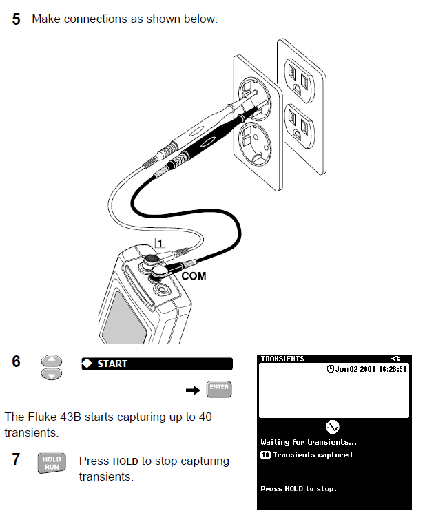

1.Observe the measured maximum or minimum peak voltage. If the peak voltage reading indicates OL (Over Load), repeat the measurement at a higher value for VOLTAGE CHANGE.

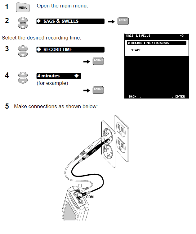
Monitoring Rapid Voltage Fluctuations
Rapid voltage fluctuations in a distribution system may cause lights to flicker. Deviations of only a few cycles (waveform periods) may result in visible dimming.
The SAGS & SWELLS function measures the rms voltage over each cycle and displays deviations.
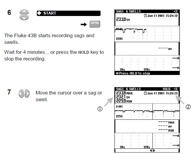
- Observe the rms voltage of the sag or swell: in case of a sag, read the minimum voltage, in case of a swell the maximum voltage.
- Observe the time when it occurred.
Determine where the sag or swell came from:
When the voltage decreases and the current does not change or only slightly, the source of the problem is upstream.
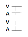
When the voltage decreases while the current increases, there is some load that causes the voltage to drop. The source of the problem is downstream.
Tip: If you find sags or swells, search for equipment which may cause them, such as large motor startups, welders, etc.
Measuring Voltage Harmonics
You can perform a quick check on harmonics in a power distribution system by measuring the Total Harmonic Distortion on the voltage.

- Look at the harmonics spectrum screen. Check the spectrum for severe harmonics.
- If the THD is lower than 5%, the voltage distortion level is probably acceptable.
Measuring Current Harmonics
Non-linear loads produce current harmonics which may cause voltage distortion.
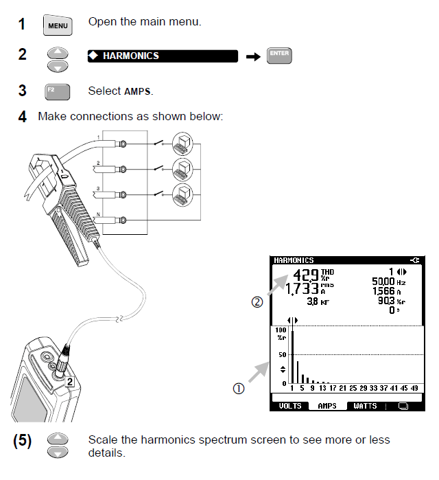
- Look at the harmonics spectrum screen. Check the spectrum for severe harmonics.
- Read the THD. It indicates the harmonic distortion on the current signal. Usually, the current signal can tolerate more harmonics than the voltage signal.
Tip: Measure harmonic currents at the point of common coupling to check whether the THD and individual harmonics comply with national standards (like IEEE-519). It is incorrect to apply such standards to specific loads.
Zero-sequence harmonics (3rd, 9th, 15th, …) add in neutral conductors or bus bars. This can cause overheating in neutral wires.
By measuring current harmonics at several places in a distribution system, you can track the harmonic source. The closer you get to the source, the more severe the current THD will be.
With FlukeView® software you can record Harmonics over time and export data to popular spreadsheet programs such as Excel.
Measuring the Load on a Transformer
Measure the total kVA on all three phases to check the load on a transformer.
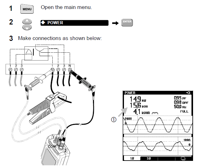
- Look at the kVA reading. It shows the apparent power on phase 1. Write down the value (kVA1).
- The symbol of a Capacitor or an Inductor is shown to indicate capacitive or inductive loads.
Compare this result with the transformer kVA rating. If the result is close to, or over the nameplate reading of the transformer, reduce the load on the transformer. If this is impossible, the transformer should be replaced by a unit with a higher kVA (or K-rating if harmonic currents are present).
Recording the Load on a Transformer
By recording the kVA during several hours, you can find out if there are specific moments during the day that the transformer may become overloaded.


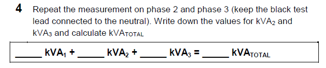
Note: Note that the kVA of only 1 phase was recorded. Record the other two phases before drawing conclusions.
Tip: Press SAVE to save the screen in memory for later documenting and analysis of the data.
Measuring K-factor
K-factor is an indication of the amount of harmonic currents. High harmonic orders influence the K-factor more than low harmonic orders.
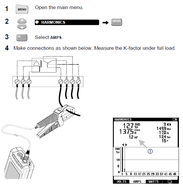
- Observe the K-factor (KF).

If the measured K-factor is higher than the K-factor specified on the transformer, you either must replace the transformer by a transformer with a higher K-rating, or reduce the maximum load on the transformer.
When choosing a replacement transformer, use the next trade-size higher than the highest measured K-factor. For example, a measurement of 10.3 KF on an installed transformer means replacing it with a K-13 unit.
