Published by David Mueller, P.E., Manager, Power System Studies, Electrotek Concepts, Inc., Knoxville, Tennessee, USA
Email: davem@electrotek.com
Presented at 2010 Georgia Tech Fault Disturbance Analysis Conference
Abstract
Wind power plants are the fastest growing power generation source, and this trend is expected to continue. This paper describes the different types of wind power turbine electrical characteristics, using the classification system as proposed by the WECC. It then discusses the relevant power quality issues of the wind turbine types and collector systems. A case study is used to illustrate the issue of harmonics and compliance with the IEEE-519 recommended limits for harmonics.
Keywords: Wind Power Plants, Utility Scale Wind Power, Flicker, Harmonics, Low Voltage Ride Through
Introduction
Owing much to the production tax credit of $.021/kW-hr, the U.S. wind industry set records for installed capacity in 2008 by installing over 8000MW of new capacity. However, the year of 2009 began with much uncertainty for the industry, as it was facing difficult financing issues along with the uncertainty of an expiring tax credit. Then the passage of the American Reinvestment Recovery Act (ARRA) revitalized the industry as it provided for new tax grants. These new grants provided for as much as 30% of the project’s capital investment (in lieu of a production tax credit). So by the end of 2009 the U.S. wind industry set yet another record with about 10,000MW of new power capacity in the U.S. These generation additions were second only to natural gas [1]. And so for the past few years the U.S. wind industry has been growing at an annual rate of about 39%, and now the industry is commonly installing utility-scale generation plants of 100MW and larger. With more penetration of these renewable resources, it is becoming more important to transmission system operators that these new plants meet or exceed requirements for maintaining utility power quality.

Pictured is the Iberdrola Wind Plant in Atchison County, Missouri
Types of Wind Turbine Generators
Typically wind turbine generators do not utilize conventional line-connected synchronous machines, but rather other machine designs. The evolution of the wind turbine design has allowed for the capture of greater power over more variable wind conditions. The type of wind turbine generator is important in evaluating their power quality characteristics. The WCC was instrumental in developing various stability models, where different wind turbine types were introduced [2].
The Type 1 Wind Turbine Generator (WTG) is shown in Figure 1. It utilizes an induction motor. It operates near synchronous speed, with a minor amount of speed variation from the slip of the motor. The operation of this machine has been described as being like “blowing on a fan”. The Type 1 WTG induction generator will always consume VARs, so it is accompanied with power factor correction. These power factor correction units are an important resonance consideration when a harmonic study is performed.

Figure 1 – Type 1 Wind Turbine Generator
The Type 2 Wind turbine generator is shown in Figure 2. In this case a wound rotor induction generator is utilized. The rotor terminals are brought external to the motor via slip rings, and the rotor resistance is controlled. This configuration allows a higher slip and a wider speed control range than available with the Type 1 WTG.

Figure 2 – Type 2 Wind Turbine Generator
The Type 3 wind turbine generator (Figure 3) is also commonly referred to as the Doubly-Fed Asynchronous Generator (DFAG) or as a Doubly-Fed Induction Generator (DFIG). In this configuration the rotor is separately powered through a double-conversion power electronic bridge. The power delivered by the machine is the net result of both power circuits. The advantage of the Type 3 wind turbine is controllability of the machine over a wide-speed range, and the ability to control power factor from leading to lagging as required by the grid. Typically, the power conversion in the rotor circuit is about 30% of the overall capacity of the machine.

Figure 3 – Type 3 Wind Turbine Generator
The Type 4 wind turbine (Figure 4) generator utilizes full power conversion via voltage source inverters. The generator operates at the mechanical optimum speed, while the inverters convert the power back to line frequency.
The inverters utilize PWM style controls, so that the current harmonics to the grid should be low (Ithd<5%).

Figure 4 – Type 4 Wind Turbine Generator
Harmonics Issues of Wind Power Plants
The Type 1 and Type 2 wind turbines are not harmonic current sources, but resonance issues are still a concern. Utility scale wind power plants typically utilize underground cable collector systems. These systems typically can utilize 50 miles of underground cable, where the total charging current can be 10MVAR. Additionally, Type 1 and Type 2 turbines will require substation capacitor banks in addition to the turbine power factor correction. All of these system capacitances combine with the system inductance to form resonance concerns. In some plants the capacitor banks have experienced failures due to high amount of harmonic currents being absorbed from system background harmonic levels.
Type 3 and Type 4 wind turbines utilize power electronics, but the voltage source inverter technology should provide for a relatively low amount of current harmonic distortion (Ithd<5%). Often the PWM switching frequency (<1kHz) provides for the highest harmonic component of the current distortion. Generally these higher order harmonics (<20th) are at dispersed phase angle representations, so that the net affect of many turbines is minimal. As with the turbines discussed in the paragraph above, most of the harmonics issues will be associated with the resonance of the collector system cables, and other reactive power support (when required).
Flicker at Wind Power Plants
Some minor power pulsations can introduce flicker power (voltage fluctuation caused by real and reactive power changes) from wind turbine generators. Additionally, cut-in and cut-out switching operations can introduce flicker, and these issues (along with voltage regulation) have to be studied very carefully for dispersed applications where single wind turbines are installed on a distribution system.
However, for utility scale wind power plants, flicker has not been a concern. The high short circuit levels of the transmission system interconnection, along with the diversity of several turbines operating independently, have been enough to minimize the concern of flicker for large wind power plants.
Overvoltage/Grounding Considerations of Wind Power Plants
Wind turbine generators, usually connected by delta-wye transformers from the 34.5kV collector system to the generator operating voltage (often 575V or 690V), do not provide their own ground source. Separate grounding transformers are usually provided on each of the 34.5kV collector circuits to provide a ground source for the condition of a single-line-to-ground fault. Following the fault, after the collector system breaker clears the fault, the circuit becomes isolated and is powered only from the wind turbines. The grounding transformer provides a fault current path and also limits the overvoltage condition on the feeder. Figure 5 below is a PSCAD/EMTDC simulation of the collector system voltage during a fault and after the clearing operation of the substation breaker.
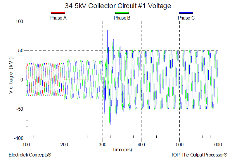
Figure 5 – PSCAD/EMTDC Simulation Result of Fault on 34.5kV Collector Circuit
Care must also be taken to insure that the transmission feed from a wind plant is grounded under various contingencies, otherwise the self-excitation of the feed from the wind turbine generators could similarly develop large overvoltage conditions, which can arise in only a few cycles. If the system is not properly grounded, these conditions can easily overwhelm the temporary overvoltage (TOV) ratings of surge arresters.
Other Interconnection Requirements of Wind Plants
Large utility-scale wind power plants are now commonly 100MW or larger. And the total penetration of wind power is becoming 10-20% in some regions (on windy days!). Accordingly, the FERC Order 661-A (2005) addressed wind power plants setting forward some requirements for reactive power, ride through capability to maintain operation during nearby fault events, and also for the sites to have two-way SCADA capabilities as required by the transmission system operator.
Initially, wind power plants with type 1 and type 2 turbines were consumers of reactive power. When the amount of wind power was relatively small, the plants could be given special treatment. Nowadays, utility-scale wind power plants are expected to act as “grown ups”, and do their part in providing reactive power. The most common requirement is for the wind plant to be able to operate at 0.95 leading and lagging. Some facilities are even required to put in dynamic reactive power control if the need is demonstrated by a study.
In the U.S. a common requirement is now for Zero Voltage Ride Through (ZVRT) for a three-phase fault for 9 cycles (0.15sec), however these requirements are relaxed for turbines installed before 2008, requiring LVRT to 0.15pu voltage for 9 cycles. Some regions have also begun to adopt overvoltage ride through recommendations for turbine wind plants.
Example Evaluation of the IEEE 519 Recommended Limits for Harmonics
Transmission system operators are requiring in their interconnection agreements with wind plants that the facility meet the harmonic limits of the IEEE Std. 519 (1992) “Recommended Practices and Requirements for Harmonic Control in Electric Power Systems”. The standard has two types of harmonic limits:
Harmonic Voltage Distortion Limits – These are often described as “utility” requirements where the grid operator must enforce the necessary current limits, and limit resonance concerns and network weakness in order to meet the maximum voltage distortion limits. The limits of Table 1 below are quite restrictive for transmission systems above 161kV.
Table 1 – IEEE 519 Harmonic Voltage Limits
| Bus Voltage | Maximum Individual Harmonic Component | Maximum THD |
|---|---|---|
| 69 kV and below | 3% | 5% |
| 115 kV to 161kV | 1.5% | 2.5% |
| Above 161kV | 1.0% | 1.5% |
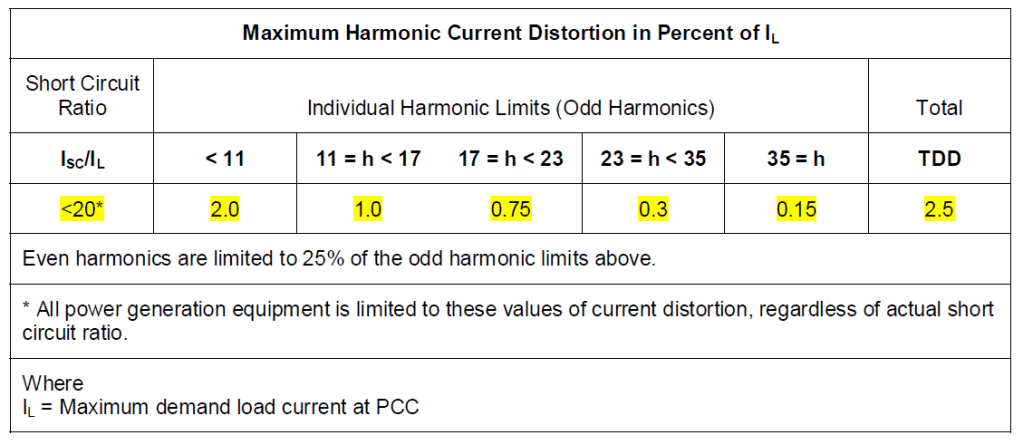
Harmonic Current Limits – These limits are applied to the currents at the point of interconnection. The short circuit ratio is irrelevant in this case, as the standard stipulates that power generation equipment must meet the most stringent limits. The standard provides the limits as a percentage of IL, the maximum current. For example each of the lower order harmonic currents must be no more than 2% of the maximum current.
Table 2 – IEEE Harmonic Current Limits for Wind Plant Connections above 69kV
So, in order to determine the harmonic currents compliance with IEEE 519, the maximum current IL must be determined. It could be plant’s full production rating (perhaps at 95% power factor). It is probably more properly determined by the maximum measured current, determined by the statistical analysis as the CP 99%, where CP stands for “cumulative probability” and CP99% is the value that exceeds 99% of measured load current. For example, in Figure 6 below the statistics data block shows that the CP 99% value is 172A, so IL = 172 A.
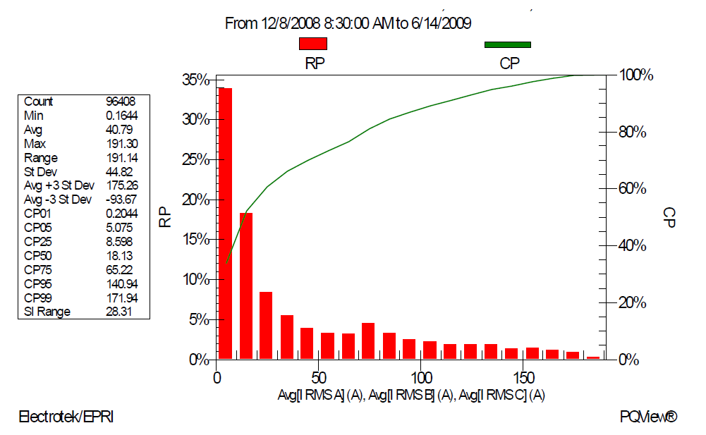
Figure 6 – Statistical Analysis of the Total Wind Plant Maximum Current
Once the maximum current, IL , is determined, then the percentages of Table 2 can be used to establish harmonic current limits at the individual harmonic frequencies, and also for the total harmonic current:
- The limit for the total harmonic current would be 2.5% x 172 A = 4.3 Amps.
- Likewise, the limit for the 5th harmonic current would be 2.0% x 172 A = 3.4 Amps.
Next, the measured harmonic currents are statistically summarized and then compared against the limits.

Figure 7 – Trend of the Measured 5th Harmonic Current
Statistical summaries of the measurements are important. Figure 7 above shows a typical trend, where certain system transient conditions caused the measured harmonic current to be above the limit of 3.4 amps. However, when the data is statistically analyzed (Figure 8), it is found that the CP95% (cumulative probability value that exceeds 95% of the measured values) is 1.3 amps, which is well below the recommended IEEE 519 harmonic current limit.

Figure 8 – Statistical Summary of the Currents at Various Harmonic Frequencies
References
[1] American Wind Energy Association, http://www.awea.org
[2] IEEE Std. 519-1992 IEEE Recommended Practices and Requirements for Harmonic Control in Electrical Power Systems.
[3] IEEE 1453-2004 IEEE Recommended Practice for Measurement and Limits of Voltage Flicker on AC Power Systems.
[4] “Development and Validation of WECC Variable Speed Wind Turbine Dynamic Models for Grid Integration Studies”, M. Behnke, A. Ellis, Y. Kazachkov, T. McCoy, E. Muljadi, W. Price, J. Sanchez-Gasca, AWEA Windpower 2007.
[5] Characteristics of Wind Turbine Generators for Wind Power Plants, IEEE PES Wind Plant Collector System Design WG, IEEE PES General Meeting, Calgary 2009.
[6] FERC Order no. 661-A, “Interconnection for Wind Energy,” Docket No. RM05-4-001, December 2005.
Biography
David Mueller is Manager of Power System Studies with Electrotek Concepts, Inc. in Knoxville, Tennessee. Dave consults on projects to study and solve power quality problems for industrial, commercial, and utility clients. He worked from 1993-1995 in Nottingham, England, starting the Power Quality Services group for East Midlands Electricity. At that time, he developed the 10-volume set of Power Quality Training Manuals. From 1998-2001 he assisted PowerGrid Ltd. in Singapore to develop their power quality capabilities. He has also worked with utilities in the US, Canada, Ireland, Brazil, China, and Malaysia. Recent projects have included studies on utility power quality compatibility levels, power system harmonics and filter designs, voltage sag mitigations, and high reliability data center power issues. Dave has a B. S. in Electrical Engineering from the University of Cincinnati and a Master of Engineering from the Electric Power Engineering Department at Rensselaer Polytechnic Institute. He is registered as a Professional Engineer in the State of Ohio.
