Published by
- Wilsun Xu and Xian Liu, Department of Electrical and Computer Engineering, University of Alberta, Edmonton, AB, Canada
- Yilu Liu, Department of Electrical Engineering, Virginia Polytechnic Institute and State University, Blacksburg, VA, USA
Published in IEEE Transaction on Power Delivery, Vol. 18, No. 1, January 2003
Abstract
The power-direction method has been used widely to identify the locations of harmonic sources in a power system. A number of utility-customer disputes over who is responsible for harmonic distortions have been settled with the help of the method. A closer examination of the method, however, reveals that it is unable to fulfill the task of harmonic source detection. Case studies can easily show that the method yields incorrect results. In this paper, problems associated with the method are investigated using case studies and mathematical analysis. The results show that the power direction method is theoretically incorrect and should not be used to determine harmonic source locations. The main cause of the problem is that the direction of active power flow is a function of the phase-angle difference between the two sources. The direction of reactive power flow, on the other hand, has a better correlation with the source magnitudes.
Index Terms – Harmonics, harmonic source detection, harmonic sources.
INTRODUCTION
Whenever significant harmonic voltage or current distortions are observed in a power system, it is always useful to find the sources of the distortions. Correct identification of harmonic source locations is essential for designing effective harmonic mitigation means and for determining the responsibility of the parties involved. The most common situation that needs harmonic source detection is to resolve the disputes over who is responsible for harmonic distortions at the point of common coupling between a utility and a customer or between two customers. The most common method for harmonic source detection is the power direction method. This method checks the direction of harmonic power flow. The side that generates harmonic power is considered to contain the dominant harmonic source or to have a larger contribution to the harmonic distortions observed at the measurement point. This method is apparently sound and has been used in industry as a tool for many years [1], [2]. A number of power quality monitors have included it as a key product feature. However, we have found concrete proofs that the method is not suitable for harmonic source detection. The method has been found theoretically incorrect. In this paper, problems associated with the method are investigated using case studies and mathematical analysis. Causes of the problem are identified. In addition, this paper proposes superposition-based indices to quantify the contributions of harmonic sources.
POWER DIRECTION METHOD
The harmonic source detection problem can be explained with the help of Fig. 1. In this figure, the disturbance sources are the customer harmonic source ![]() and the utility harmonic source
and the utility harmonic source ![]() .
. ![]() and
and ![]() are the harmonic impedances of the respective parties. The circuit is applicable to different harmonic frequencies (the values will be different). The task of harmonic source detection is to determine which side contributes more to the harmonic distortion at the PCC, subject to the constraint that measurements can only be taken at the PCC.
are the harmonic impedances of the respective parties. The circuit is applicable to different harmonic frequencies (the values will be different). The task of harmonic source detection is to determine which side contributes more to the harmonic distortion at the PCC, subject to the constraint that measurements can only be taken at the PCC.
To determine which side causes more harmonic distortion at the harmonic order h, the power direction method first measures voltage and current at the PCC and then calculates the following harmonic power index:

where ![]() and
and ![]() are the harmonic voltage and current at the PCC for a particular harmonic number. Since this paper deals with one harmonic at a time, the subscript h that represents harmonic number h will be omitted throughout the paper to avoid excessive subscripts. The direction of P is defined as from U side to the C side. Conclusion of the power direction method is the following.
are the harmonic voltage and current at the PCC for a particular harmonic number. Since this paper deals with one harmonic at a time, the subscript h that represents harmonic number h will be omitted throughout the paper to avoid excessive subscripts. The direction of P is defined as from U side to the C side. Conclusion of the power direction method is the following.
- If P > 0, the U side causes more hth harmonic distortion.
- If P > 0, the C side causes more hth harmonic distortion.

Fig. 1. Problem of harmonic source detection.
QUANTITATIVE HARMONIC CONTRIBUTION INDICES
While the power direction method could be intuitively sound, the term “causing more harmonic distortions” is vaguely defined. There is a need to be more precise on this term so that the effectiveness of any harmonic source detection methods can be assessed. To this end, the principle of superposition is applied to the hth system shown in Fig. 1 [3]. According to the principle, the contribution of each source to the hth harmonic current ![]() can be determined according to Fig. 2 and the following equations:
can be determined according to Fig. 2 and the following equations:

where ![]() and
and ![]() are the contributions of respective sources to the PCC current. Again, all quantities in Fig. 2 and (2) refer to a particular harmonic, the hth harmonic. The equations shown before are phasor equations. There are still some ambiguities to define harmonic contributions since (2c) is a phasor summation. A more precise method is to decompose
are the contributions of respective sources to the PCC current. Again, all quantities in Fig. 2 and (2) refer to a particular harmonic, the hth harmonic. The equations shown before are phasor equations. There are still some ambiguities to define harmonic contributions since (2c) is a phasor summation. A more precise method is to decompose ![]() into two scalar components as shown in Fig. 3 and (3) [4]
into two scalar components as shown in Fig. 3 and (3) [4]

where ![]() is the projection of
is the projection of ![]() onto
onto ![]() , and
, and ![]() is the projection of
is the projection of ![]() onto
onto ![]() . Thus
. Thus ![]() , is the algebraic summation of two scalar components, one due to customer harmonic source and the other due to utility source. For example
, is the algebraic summation of two scalar components, one due to customer harmonic source and the other due to utility source. For example ![]() , if is equal to 3 A and
, if is equal to 3 A and ![]() is equal to 7 A,
is equal to 7 A, ![]() the current is 10 A. One can say that the customer’s contribution is 70%.
the current is 10 A. One can say that the customer’s contribution is 70%.
Both ![]() and
and ![]() are scalars and can have opposite signs. If they have the same sign, the customer and utility harmonics add up to form
are scalars and can have opposite signs. If they have the same sign, the customer and utility harmonics add up to form ![]() . If they have opposite signs, the negative one has the effect of reducing the harmonic flow at PCC. We believe that the
. If they have opposite signs, the negative one has the effect of reducing the harmonic flow at PCC. We believe that the ![]() and
and ![]() indices accurately characterize the contributions of respective harmonic sources to the PCC current. They are used in this paper to refute the validity of the power direction method.
indices accurately characterize the contributions of respective harmonic sources to the PCC current. They are used in this paper to refute the validity of the power direction method.

Fig. 2. Determination of harmonic source contributions for hth harmonic.

Fig. 3. Decomposition of ![]() of the hth harmonic into two components.
of the hth harmonic into two components.
A similar index can be defined from the voltage distortion perspective. The contribution to voltage distortions at PCC by each harmonic source can be determined as follows

Again, the phasors ![]() and
and ![]() need to be projected onto the
need to be projected onto the ![]() axis to provide scalar harmonic contribution indices. The process is similar to what has been applied to the current indices.
axis to provide scalar harmonic contribution indices. The process is similar to what has been applied to the current indices.
SAMPLE TEST RESULTS
The validity of the power direction method can be tested with the following simple experiment:
1) Select a set of practical ![]() ,
, ![]() ,
, ![]() and
and ![]() data that correspond to any particular harmonic number. In this paper, we chose the following case:
data that correspond to any particular harmonic number. In this paper, we chose the following case:

Let the phase angle of ![]() vary from 0° to 360° . Phase angle of
vary from 0° to 360° . Phase angle of ![]() is set to 0° as a reference.
is set to 0° as a reference.
2) Check the correlation between the power direction index and the superposition indices. If the power direction method was correct, the following condition should always hold:
![]()
Fig. 4 shows the results. The figure depicts the variation of normalized harmonic power P, current ![]() , and its components
, and its components ![]() and
and ![]() with respect to the phase angle of
with respect to the phase angle of ![]() . The normalization divides the currents and power by their respective maximum values so that they reside between the range of -1 to +1 and can be easily plotted in one chart for comparison. It can be clearly seen from the figure that the condition shown before (5) does not always hold true. For example
. The normalization divides the currents and power by their respective maximum values so that they reside between the range of -1 to +1 and can be easily plotted in one chart for comparison. It can be clearly seen from the figure that the condition shown before (5) does not always hold true. For example ![]() , is always greater than
, is always greater than ![]() and C the side should be considered as the main harmonic current contributor. The harmonic power, on the other hand, can flow in either direction. When the angle is greater than 190° , the power direction contradicts to the principle of superposition. There is an approximate 50% chance that the contradiction can occur. Fig. 5 is a practical case that can create a situation where the phase angle between
and C the side should be considered as the main harmonic current contributor. The harmonic power, on the other hand, can flow in either direction. When the angle is greater than 190° , the power direction contradicts to the principle of superposition. There is an approximate 50% chance that the contradiction can occur. Fig. 5 is a practical case that can create a situation where the phase angle between ![]() and
and ![]() is far apart. Since there is no guarantee that the phase angle between
is far apart. Since there is no guarantee that the phase angle between ![]() and
and ![]() resides in a certain range, one can conclude that the power direction method is unsuitable for harmonic source detection.
resides in a certain range, one can conclude that the power direction method is unsuitable for harmonic source detection.
Test results are also obtained for the voltage distortion index defined in (4). The results are shown in Fig. 6. It is noted that, according to the voltage superposition index, the C side contributes more to the PCC voltage distortion. This conclusion applies to all customer current angles. The power direction index, however, changes sign when the current angle is between 190° and 340° . The contradiction between the two indices is obvious.

Fig. 4. Correlation between the power direction and current superposition indices.

Fig. 5. A practical case that can cause large phase-angle difference between![]() and
and![]() .
.

Fig. 6. Correlation between the power direction and voltage superposition indices.
MATHEMATICAL ANALYSIS
Figs. 4 and 6 can be produced easily for many test cases. The evidence against the power direction method is overwhelming. This finding is also supported by the results shown in [5] and [6]. In this section, we try to demonstrate mathematically that the contradiction does exist. The sources of the contradiction are also identified and explained.
DC Circuit Case
The first case is a general dc circuit shown in Figs. 7 and 8. Although the actual harmonic source detection problem involves ac circuits, the dc circuit case can reveal key characteristics of the power direction method. A dc circuit is much simpler to analyze since there is no phasor involved. The dc case can also be considered a special ac case where the system has resistances only and the harmonic sources have the same phase angle.

Fig. 7. DC circuit to demonstrate the power direction method (![]() and
and![]() oppose each other).
oppose each other).
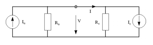
Fig. 8. DC circuit to demonstrate the power direction method (![]() and
and![]() add up).
add up).
The PCC voltage and current of the circuit can be determined as follows:

Since the voltage is always positive, the condition for the power ( =VI) to flow from U side to C side is I > 0 or
![]()
On the other hand, the superposition current index shows that if

or

holds, the U side contributes more current than the C side. Equations (7) and (9) are therefore consistent, which implies that the power direction method works well in this case. If the customer current ![]() changes polarity as shown in Fig. 8, however, the current I becomes positive all of the time. The condition for the power to flow from U side to C side is V > 0, or
changes polarity as shown in Fig. 8, however, the current I becomes positive all of the time. The condition for the power to flow from U side to C side is V > 0, or
![]()
[based on Equation (6b)]. The condition for ![]() >
> ![]() is still the same as that shown in (9). This equation does not always agree with (10), depending on the relative size of
is still the same as that shown in (9). This equation does not always agree with (10), depending on the relative size of ![]() and
and ![]() . Therefore, a mathematical proof has been found to show that there is a contradiction between the power direction method and the superposition method. Another conclusion drawn from the analysis is that the polarity (or phase) difference between the two sources has more influence on the direction of power flow than that caused by their magnitude difference.
. Therefore, a mathematical proof has been found to show that there is a contradiction between the power direction method and the superposition method. Another conclusion drawn from the analysis is that the polarity (or phase) difference between the two sources has more influence on the direction of power flow than that caused by their magnitude difference.
AC Circuit with Reactance Only
The second case is an ac circuit shown in Fig. 1. To simplify the analysis, the impedances are assumed to contain imaginary parts only. The circuit corresponds to a particular harmonic frequency. Following the classic power-angle equation for two source ac circuits, the power flowing from U side to C side can be determined as:

where ![]() and
and ![]() are the open circuit hth harmonic voltages of the U and C sides, respectively. δ is the phase-angle difference between utility and customer side hth harmonic current sources. The significance of this equation is the following: the direction of power is controlled by δ, the phase-angle difference between two harmonic sources.
are the open circuit hth harmonic voltages of the U and C sides, respectively. δ is the phase-angle difference between utility and customer side hth harmonic current sources. The significance of this equation is the following: the direction of power is controlled by δ, the phase-angle difference between two harmonic sources.
For the superposition-based current index, we want to show at first that condition ![]() >
> ![]() implies
implies ![]() >
> ![]() . According to Fig. 3 and the well-known triangular formula, the superposition currents
. According to Fig. 3 and the well-known triangular formula, the superposition currents ![]() and
and ![]() can be determined as follows:
can be determined as follows:

Therefore

Subtracting the above two equations yields
![]()
This equation shows that if ![]() >
> ![]() is satisfied,
is satisfied, ![]() >
> ![]() will be true. Note that this is a general conclusion. It does not rely on the assumption of the impedances having imaginary parts only. In the following step, the relationship between the superposition currents and the source currents is determined. The principle of superposition shows:
will be true. Note that this is a general conclusion. It does not rely on the assumption of the impedances having imaginary parts only. In the following step, the relationship between the superposition currents and the source currents is determined. The principle of superposition shows:

The condition for ![]() >
> ![]() or
or ![]() >
> ![]() to hold becomes
to hold becomes

The condition just mentioned is not related to phase-angle , while (11) is. The power direction index is therefore inconsistent with the current superposition index. Hence, the invalidity of the power direction index has been demonstrated analytically. The same process can be used to show the inconsistency between the power index and voltage-based superposition index.
It is common knowledge for power engineers that the phase angles of bus voltages mainly affect the flow of active power while the magnitudes of bus voltages mainly affect the flow of reactive power. One would, therefore, wonder if the direction of reactive power could indicate the relative size (i.e., magnitudes) of two harmonic sources. This question can be analyzed by examining the reactive power flowing out of source

Where δ is the phase-angle difference between the two sources. Since cos δ is always less than 1 and if ![]() +
+ ![]() > 0, condition
> 0, condition ![]() >
> ![]() automatically implies that the direction of reactive power is from U side to the C side. In other words, the direction of reactive power can be used as an (necessary but not sufficient) indicator to determine which side has a larger voltage source. The reason that the indicator is not a sufficient one is because the reactive power can still flow from U side to the C side if
automatically implies that the direction of reactive power is from U side to the C side. In other words, the direction of reactive power can be used as an (necessary but not sufficient) indicator to determine which side has a larger voltage source. The reason that the indicator is not a sufficient one is because the reactive power can still flow from U side to the C side if ![]() is greater than
is greater than ![]() but
but ![]() cos δ is less than
cos δ is less than ![]() . The phase-angle δ , therefore, plays an important role in this case as well. Despite this restriction, the direction of reactive power is still a more reliable indicator than the direction of active power in this case. Another important prerequisite for using the direction of reactive power as a harmonic source locator is
. The phase-angle δ , therefore, plays an important role in this case as well. Despite this restriction, the direction of reactive power is still a more reliable indicator than the direction of active power in this case. Another important prerequisite for using the direction of reactive power as a harmonic source locator is ![]() +
+ ![]() > 0. While this condition is generally true at the fundamental frequency, it may not be true at the harmonic frequencies. This is the main problem associated with the reactive power direction method.
> 0. While this condition is generally true at the fundamental frequency, it may not be true at the harmonic frequencies. This is the main problem associated with the reactive power direction method.
AC Circuit with Resistances Only
It is interesting and important to examine the hypothetical case where the system and customer impedances are entirely resistive, namely, ![]() =
=![]() and
and ![]() =
=![]() . In this case, the branch resistance consumes power. The amount and direction of the active power flowing on the branch are dependent on the location of measurement. To simplify the problem, we first consider the power generated or absorbed by harmonic source
. In this case, the branch resistance consumes power. The amount and direction of the active power flowing on the branch are dependent on the location of measurement. To simplify the problem, we first consider the power generated or absorbed by harmonic source ![]() , as shown in Fig. 9. For this case, the power flowing out of source
, as shown in Fig. 9. For this case, the power flowing out of source ![]() is
is

Where δ is the phase-angle difference between the two sources. It can be seen that (18) is very similar to (17). It means that the direction of active power can be used as an (necessary but not sufficient) indicator to determine which side has a larger voltage source for the resistive circuit. The reactive power flow for this case takes the following form:

This equation is very similar to (11). Comparing (11) to (19), and (17) to (18), one can conclude that the characteristics of the circuit impedance ![]() +
+ ![]() determine which power P, or Q, has more bearing on the source magnitudes instead of source phase angles. If the circuit impedance is dominated by reactance, the direction of reactive power is a better indicator on the relative magnitude of the two sources. If the impedance is dominated by resistance, however, the direction of active power is a better indicator.
determine which power P, or Q, has more bearing on the source magnitudes instead of source phase angles. If the circuit impedance is dominated by reactance, the direction of reactive power is a better indicator on the relative magnitude of the two sources. If the impedance is dominated by resistance, however, the direction of active power is a better indicator.
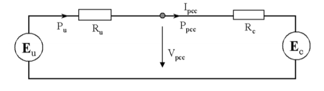
Fig. 9. AC circuit with resistive elements.
The second analysis deals with a general case where the metering point is the PCC. As shown in Fig. 9, the PCC voltage and current can be determined as follows:

The active power flowing from U side to C side can be determined as

The equation just shown reveals that the resistances ![]() and
and ![]() could have a large impact on the sign of
could have a large impact on the sign of  , or the direction of active power. We can quantify the impact by considering the special case of
 ![]() =
=![]() . For this case, Equation (21) can be simplified as
. For this case, Equation (21) can be simplified as

The equation just shown demonstrates clearly that the direction of active power P is affected by the relative size of ![]() and
and ![]() or the location of the meter. If
or the location of the meter. If ![]() >
> ![]() , the power flows from U side to C side, even if the two sources have the same magnitude. This analysis has revealed another impact factor, the point of measurement, which can influence the reliability of the power direction method.
, the power flows from U side to C side, even if the two sources have the same magnitude. This analysis has revealed another impact factor, the point of measurement, which can influence the reliability of the power direction method.
CONCLUSION
The concern for power system harmonics is mainly on the distortion of sinusoidal voltage and current waveforms. Even with little harmonic power, a distorted waveform can trigger the malfunction of electronic circuits. It is, therefore, important to define the contribution of each harmonic source based on the current and/or voltage parameters. This paper proposes superposition-based current and voltage indices to quantify the contributions of harmonic sources. Using these indices, the validity of the power direction method for harmonic source determination is investigated. Both case studies and mathematically analyses have shown that the power direction method is not suitable for harmonic source detection. Main findings of this work are summarized as follows.
1) The direction of active power is mainly affected by the relative phase angle between the two harmonic sources. It has little bearing on the relative magnitude of the sources. Note that it is the source magnitudes instead of phase angles that are of main interest for the harmonic source detection problem.
2) The direction of reactive power, on the other hand, has a closer relationship to the source magnitudes. If the circuit impedance is purely reactive, the direction of reactive power is actually a necessary (but not sufficient) condition indicating one source has a larger magnitude than the other.
3) The conclusions shown above are applicable to circuits dominated by reactances. If a circuit consists of mainly resistive components, the conclusions mentioned before are reversed. Namely, the direction of active power is mainly affected by the source magnitudes and that of the reactive power by the phase angles. The implication of this conclusion is that the characteristics of the circuit impedance ( R – X ratio) will affect the reliability of the active or reactive power-direction-based harmonic source detection methods.
4) The metering point or the relative size of the source and the customer impedances will also affect the direction of either active or reactive powers. This is another important factor that makes the power-direction-based methods unreliable. The (active) power direction method has been used frequently as a practical method for locating harmonic sources. This work has shown that the method does not work and there is an urgent need to develop new harmonic source detection methods.
ACKNOWLEDGMENT
The authors wish to express sincere thanks to M. B. Hughes of BC Hydro for valuable comments during the course of this work.
REFERENCES
[1] P. H. Swart, M. J. Case, and J. D. Van Wyk, “On techniques for localization of sources producing distortion in three-phase networks,” Eur. Trans. Elect. Power Eng., vol. 6, no. 6, Nov./Dec. 1996.
[2] L. Cristaldi and A. Ferrero, “Harmonic power flow analysis for the measurement of the electric power quality,” IEEE Trans. Instrum. Meas., vol. 44, pp. 683–685, June 1995.
[3] H. Yang, P. Porotte, and A. Robert, “Assessing the harmonic emission level from one particular customer,” in Proc., 1994.
[4] W. Xu and Y. Liu, “A method for determining customer and utility harmonic contributions at the point of common coupling,” IEEE Trans. Power Delivery, vol. 15, pp. 804–811, Apr. 2000.
[5] A. E. Emanuel, “On the assessment of harmonic pollution,” IEEE Trans. Power Delivery, vol. 10, pp. 1693–1698, July 1995.
[6] M. B. Marz, J. F. Witte, D. L. Williams, and P. M. Thompson, “Finding and determining the influence of multiple harmonic sources on a utility system using harmonic measurements,” in Power Quality 2000 Conf., Boston, MA, Oct. 2000.
