Published by Dranetz – BMI Case Studies
Executive Summary
Defiance Metal Products Company contracted with Electrotek Concepts to perform field measurements of their welding operations, and to make recommendations for remediation of Power Quality problems at the facility.
The customer has been experiencing both major and minor electrical problems. The minor problems include occasional observable flicker in the overhead HID lighting system. The major problems include welder trip during operation and damage to protective MOVs.
Electrotek Concepts engineer installed a Dranetz 8020 PQ Node at the 2000 amps main service disconnect to monitor overall plant electrical power quality during the survey. Measurements were taken at individual spot welders using a Dranetz Power Platform PP1. The service voltage is 277/480 grounded wye.
The customer has upgraded the electrical service to the welding building from a 300 kVA transformer to a 1500 kVA unit. This action has achieved a very stable voltage waveform as seen by the various welders. Even with heavy current draws, the voltage waveform showed very little notching and no significant transients were detected. The only drawback to such a “stiff” service supply is the availability of greater fault current flow in case of short circuits or heavy welder loading. This high available fault current should be taken into consideration in the sizing and rating of fuses and circuit breakers.
The proper operation of the welding equipment is dependent not only upon the quality of the electrical power at the main service but also the quality of the electrical power in the main welder circuits. The high currents involved can cause premature deterioration and failure of any non-bolted electrical connections in the overall power circuit, such as the contacts in circuit breakers and electrical contactors and power relays. The electronic firing circuits will attempt to balance-out the problem of phase imbalance during the weld cycle, but extreme voltage excursions (as can happen with damaged electrical contacts) cannot be fully compensated for. The results will be occasional bad welds and system faults.
Some of the readings taken during welder operation did indicate the possibility of poor electrical conductivity in the welder circuit. This was later confirmed when the suspect circuit breaker was inspected and found to have severely burned contacts.
The report is organized with the following further observations:
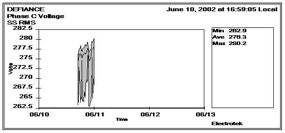
Measurements – 8020 PQ Node. These readings were taken at the main service entrance and profile the voltage and current for the entire welding operation. Charts are drawn to illustrate these profiles as well as noteworthy electrical disturbances that were triggered during the site visit.
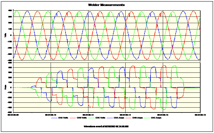
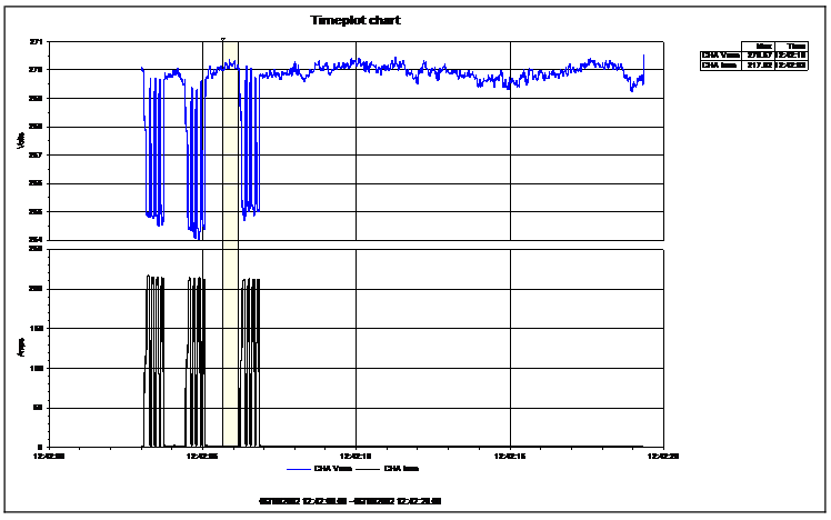
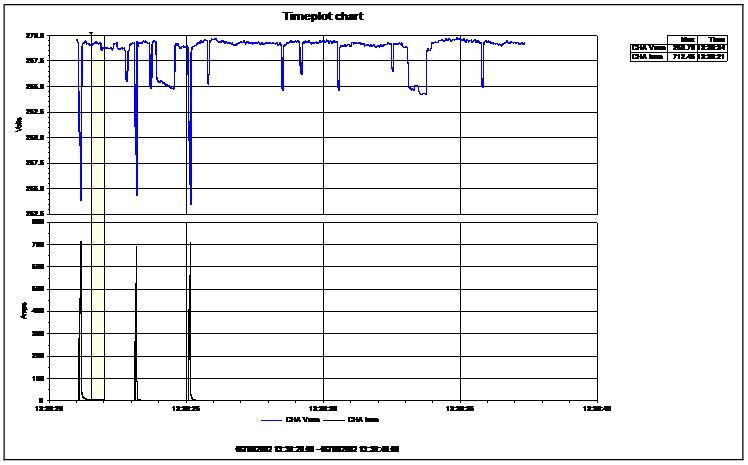
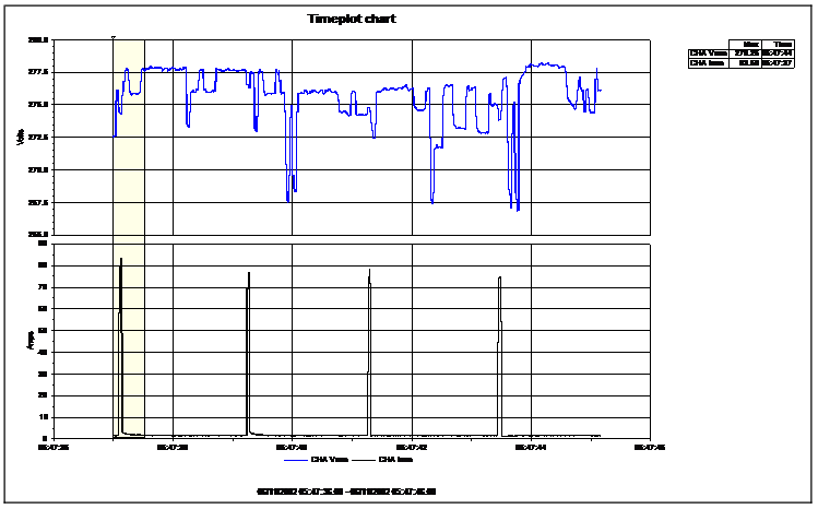
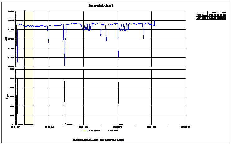
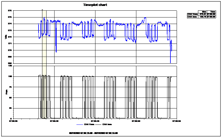
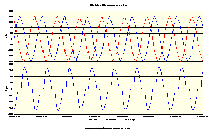
Measurements – Power Platform PP1. These readings were taken at individual welder locations and the charts show the voltage and current variations during typical weld cycles.
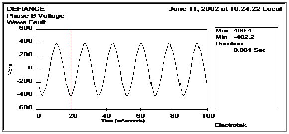
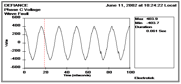
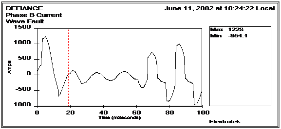
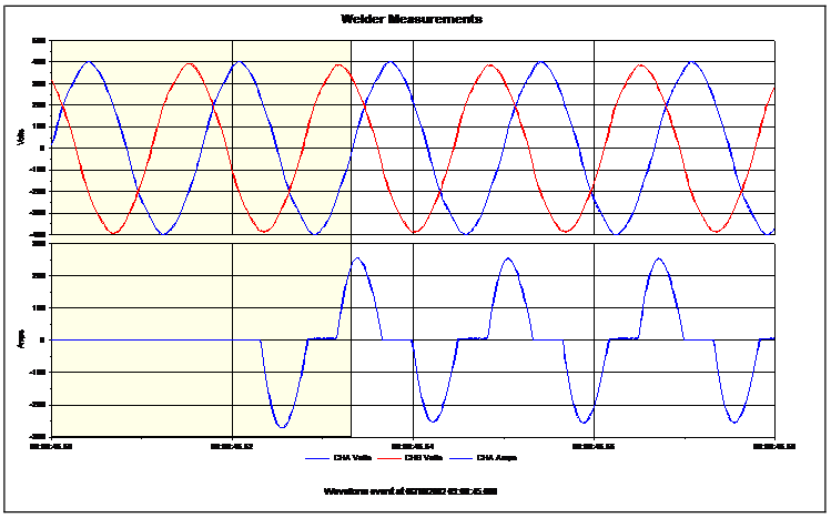
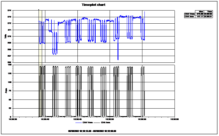
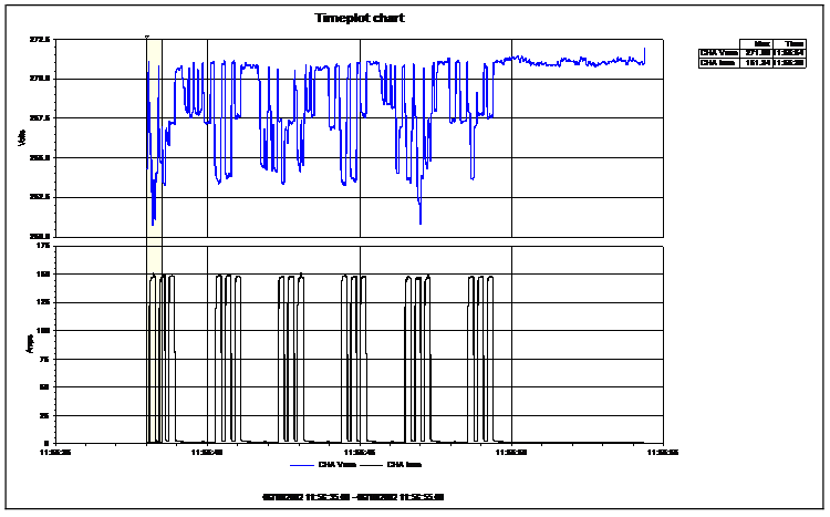
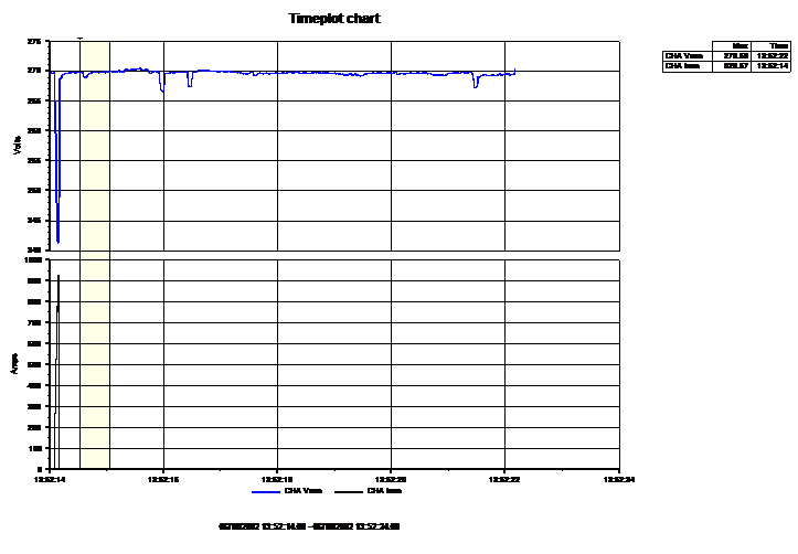
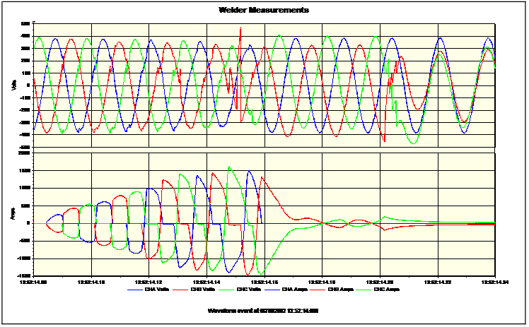
Of special interest is Figure 32, which shows the voltage change as the circuit breaker on Welder 121-R is closed. Notice the voltage does not change smoothly, which is indicative of poor conductivity of the circuit breaker contacts. Also note Figures 36 and 38, which show voltage transients on Phase “B” during a welder fault. These voltage profiles also suggest a problem with electrical continuity on the center phase of the circuit breaker. Subsequent inspection of the circuit breaker proved this to be true.
Measurements – 8020 PQ Node


Measurements – Power Platform PP1


Conclusions and Recommendations
The electrical measurements on the 3-phase welder 121-R were made on the load side of the molded-case circuit breaker in the welder panel. A voltage transient was noted on the “B” phase that could not be fully explained unless one considered a break in the supply voltage to that phase. Examination of the circuit breaker revealed heavily burned contacts and, in essence, zero-conductivity in the center phase. These “cold” characteristics could easily change when the breaker is energized, and it seems it has been delivering at least partial power in the period before its failure. However, the damage to the circuit breaker contacts could easily explain why this particular welder experienced random failures.
This same logic could be used to explain problems occurring with other welders. At the time of the survey, it was not conclusive that all important electrical contacts in the other welders (especially circuit breakers and contactors) were in good shape. All should be considered under suspicion, and further considerations as to what could still be causing problems should be suspended until an analysis is made of existing circuit conditions. At a minimum, this would consist of cold-load ohmmeter measurements of conductivity and full-load tests of voltage drop across circuit breaker and contactor line and load terminals.
