Published by Dranetz – BMI Case Studies
Engineering laboratory adjacent to offices. A computer system used by laboratory personnel exhibited intermittent failures and data errors. Typically, these would start around 10 a.m. On some days there were no failures.
A power monitor was installed at the panelboard serving the computer system. The monitor was connected, line-to-neutral (Channel A) and neutral-to-ground (Channel B). The recorded line-to-neutral waveforms were relatively undistorted sine waves, which gave no clues as to the source of the line disturbances.
An event summary of the RMS voltage, Figure 1, revealed a pattern of repetitive sags in the RMS voltage, beginning just after 10 a.m. The regular nature of these sags, as well as corresponding swells on the neutral, were made even clearer by increasing the resolution to a few minutes, Figure 2.


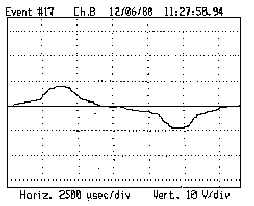
The regular repetition of the voltage sags was a powerful clue, indicating automatic switching of another load on the circuit. The neutral-to-ground waveform, Figure 3, indicated the load was linear.
A little more detective work soon located a laser printer in one of the nearby offices whose print fusing heater switched on every minute or so. The high current demand and resulting potential developed on the neutral was causing the computer errors. The printer was usually powered up around 10 a.m., after the user had created text to be printed. Moving the printer to another branch circuit removed the source of computer interference.