Published by 1. Mohd Afifi JUSOH, 2. Muhamad Zalani DAUD, 3. Mohd Zamri IBRAHIM,
Faculty of Ocean Engineering Technology and Informatics, Universiti Malaysia Terengganu, 21030 Kuala Nerus, Terengganu Malaysia
ORCID: 1. 0000-0001-9929-4640; 2. 0000-0003-3003-3068; 3. 0000-0002-9439-8552
Abstract. The inconsistency of solar irradiance and temperature have led to unpredictable output power fluctuation of photovoltaic (PV) system. This paper proposes a simple control scheme for hybrid energy storage (HES) system to mitigate the long-term and short-term output power fluctuations of the PV system. The proposed control scheme employed the fuzzy logic controller in order to manage the power compensation of the HES system and to maintain the state-of-charge (SOC) level of the HES system within safe operating limits during the mitigation process. In the control scheme, the long-term output power fluctuation is eliminated by using battery energy storage, while short-term output fluctuation is compensated using the ultracapacitor. Apart from that, an hourly PV power dispatch was applied in the control scheme since the grid-connected PV system was considered in this study. The simulation evaluations of PV/HES with the proposed control scheme was conducted in the MATLAB/Simulink environment. The effectiveness of the proposed control scheme was verified through several case studies. Initially, the control scheme was evaluated with different initial SOC levels of HES. Then, the control scheme was evaluated using five days of actual PV system output in order to verify the robustness of the proposed control scheme in actual circumstances. Overall, the simulation evaluation was verified that the proposed control scheme of the PV/HES system effectively mitigates the output power fluctuations of the PV system and output power is dispatched out to the utility grid on an hourly basis. Also, it was able to regulate the SOC of HES at the operational limit throughout the process. The simulation result showed the control scheme successfully reduced the unacceptable output power fluctuation from 20% to less than 1%. The results also showed the SOC of HES was regulated within the range of 38%-75% and 42%-60% of its capacity along the process, respectively.
Streszczenie. Niespójność natężenia promieniowania słonecznego i temperatury doprowadziła do nieprzewidywalnych wahań mocy wyjściowej systemu fotowoltaicznego (PV). W niniejszym artykule zaproponowano prosty schemat sterowania hybrydowym systemem magazynowania energii (HES) w celu złagodzenia długo- i krótkoterminowych wahań mocy wyjściowej systemu fotowoltaicznego. Zaproponowany schemat sterowania wykorzystywał sterownik logiki rozmytej w celu zarządzania kompensacją mocy systemu HES i utrzymania poziomu stanu naładowania (SOC) systemu HES w bezpiecznych granicach operacyjnych podczas procesu mitygacji. W schemacie sterowania długoterminowe wahania mocy wyjściowej są eliminowane przez zastosowanie magazynowania energii akumulatora, podczas gdy krótkotrwałe wahania mocy wyjściowej są kompensowane za pomocą ultrakondensatora. Poza tym w schemacie sterowania zastosowano godzinową dyspozytornię mocy fotowoltaicznej, ponieważ w niniejszym opracowaniu uwzględniono system fotowoltaiczny podłączony do sieci. Oceny symulacyjne PV/HES z proponowanym schematem sterowania przeprowadzono w środowisku MATLAB/Simulink. Skuteczność proponowanego schematu kontroli zweryfikowano za pomocą kilku studiów przypadku. Początkowo schemat kontroli oceniano przy różnych początkowych poziomach SOC HES. Następnie schemat sterowania został oceniony przy użyciu pięciu dni rzeczywistej mocy wyjściowej systemu fotowoltaicznego w celu zweryfikowania niezawodności proponowanego schematu sterowania w rzeczywistych warunkach. Ogólnie rzecz biorąc, ocena symulacji została zweryfikowana, że proponowany schemat sterowania systemem PV/HES skutecznie łagodzi wahania mocy wyjściowej systemu fotowoltaicznego, a moc wyjściowa jest wysyłana do sieci energetycznej co godzinę. Ponadto był w stanie regulować SOC HES na limicie operacyjnym podczas całego procesu. Wyniki symulacji wykazały, że schemat sterowania skutecznie zmniejszył niedopuszczalne wahania mocy wyjściowej z 20% do mniej niż 1%. Wyniki pokazały również, że SOC HES był regulowany w zakresie odpowiednio 38%-75% i 42%-60% jego pojemności w trakcie procesu. (Strategia sterowania oparta na logice rozmytej dla godzinowej wysyłki mocy fotowoltaiki podłączonej do sieci z hybrydowym magazynowaniem energii)
Keywords: photovoltaic system, battery energy storage, ultracapacitor, control strategy, fuzzy control
Słowa kluczowe: system fotowoltaizny, logika rozmyta, .magazynowanie energii.
1.0 Introduction
Renewable energy (RE) sources have been rapidly developed throughout the world over the past two decades due to fossil fuel depletion and severe environmental pollution. Photovoltaic (PV) energy, is environmental friendly energy that is being considered as a potential replacement for traditional energy sources. However, due to the intermittent nature of solar irradiance and temperature, the output from PV sources are unpredictable, inconsistent and randomly fluctuate [1]. The fluctuation of the output power from PV sources can bring some negative impacts to grid security such as voltage deviation, voltage fluctuation, harmonic and other power quality problems. These problems are some of the obstacles to the efforts of increasing the penetration level of PV power in power grids [2]. In order to reduce these negative impacts, several control strategies have been proposed in the literature for smoothing the output power fluctuations of PV sources, for example in [3]–[11].
One of the methods is mitigation of power fluctuation by geographical dispersion [3]–[5]. Normally, geographical dispersion is used to mitigate the short term output fluctuations for PV clusters installed in a wide area. Another approach is by curtailment of active power by employing Maximum Power Point Tracking (MPPT) controller, which limits the output power of PV sources [6-9]. The conventional method of mitigating the power fluctuation is by using the diesel generator [10], [12]. However, due to slow response and poor efficiency of diesel generator, it leads to difficulty when it comes to handling the high power ramp of PV fluctuations. Furthermore, a diesel generator is not an environmentally friendly solution. Recent trends in power fluctuation mitigation strategy are by using fast response and enhanced flexibility of storage technologies such as battery energy storage (BES), ultracapacitors (UC), flywheel and fuel cells [1], [13]–[15].
Presently, BES and UC are considered great alternatives for mitigating the long-term and short-term output power fluctuations. There are many types of batteries used for BES applications such as flooded leadacid (LA) batteries, valve-regulated lead-acid (VRLA) batteries, nickel-cadmium (NiCd) batteries, lithium-ion (Liion) batteries, sodium-sulfur (NAS) batteries and vanadium redox (VRB) batteries [16]. The various advantages of using an energy storage system in PV system applications are discussed in detail in [16], [17]. The combination of multiple types of energy storage devices with various charge and discharge behaviour is a great solution to mitigate the short-term and long-term output power fluctuations. Thus, this study focuses on the hybridization of Li-ion batteries and UC as a mitigation strategy for output power fluctuations of the PV sources.
From the literature, several control methods have been proposed for mitigating PV output power fluctuations using the HES system that utilizes BES and UC [18]–[21]. In [19], a fuzzy-logic-based adaptive power management system for smoothing PV power output has been proposed. The proposed system managed the power-sharing between UC and BES according to their operational constraints, such as voltage limit, charge/discharge current limit, state-of-charge (SOC) limit, etc. Similarly, a multimode fuzzy logic-based control scheme BES and UC has been proposed in [21]. The control scheme was designed to optimize the operation of BES and UC as well as prevent them from performing under extreme conditions. In this regard, the flexibility of fuzzy logic controllers provide superior performance in many electric power system applications particularly in managing the output power fluctuations of RE sources. The range of fuzzy logic-based applications can also be found in PV system MPPT designs [22] for extracting maximum power from the solar PV system, wind energy generation system or the hybrid wind-PV system. In [19] fuzzy logic has been used in smoothing the solar PV output power fluctuations. Whereas in [10] fuzzy control method has been used for mitigating output power fluctuation by using a diesel hybrid power system. The proposed method is necessary for considering the conflicting objective of maximizing energy captive and output power levelling. The simulation results showed that the proposed method was feasible in levelling output power fluctuations and reducing the frequency deviation. In [23], an optimal hourly energy management system for hybrid wind, PV system, hydrogen and battery system with supervisory control based on fuzzy logic has been developed. The fuzzy logic controller is used in an hourly energy management system to maintain the energy flow while optimizing the utilization cost and lifetime of the energy storage system.
This paper proposes a fuzzy logic-based hourly dispatch control scheme for a grid-connected PV system with HES (PV/HES) system. The objective is to design the optimal control scheme for a hybrid PV system with BES and UC to reduce the output power fluctuation from the PV system. The presented control scheme offers superior reliability and effective performance for the PV/HES system. The simulation results demonstrated that the control scheme could maintain the system operation of PV/HES within the desired limitations while dispatching a stable output power to the grid system. The main contribution of this paper can be described based on the control scheme that has been developed for regulating the charging and discharging of BES and UC to smooth out the PV output power fluctuations.
The rest of the paper is organized as follows: Section 2 generally describes the grid-connected PV/HES system considered in the present study. Section 3 describes the modelling process of grid-connected PV/HES system for simulation studies. Section 4 presents the proposed fuzzylogic based control scheme. Section 5 provides the simulation results and discussion and Section 6 concludes the paper.
2.0 Grid-Connected PV/HES system
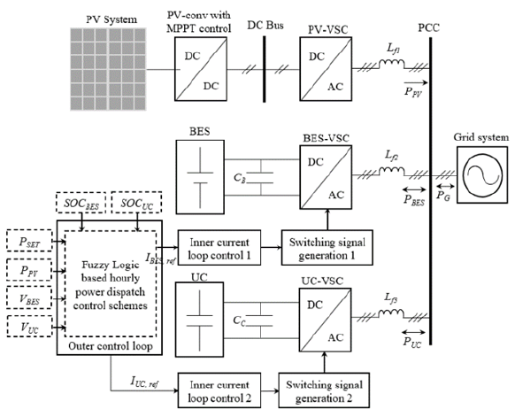
The overall system configuration of the hybrid PV/HES system with the proposed control scheme is shown in Fig. 1. Based on the figure, the grid-connected and ac-coupled concept of PV/HES was considered in the present study. The figure shows grid-connected PV system is parallelly connected to HES at the point of common coupling (PCC) bus via a voltage-sourced converter (VSC).
The purpose of the BES-VSC and UC-VSC is to regulate the fluctuated output power from the PV system (PPV) according to the reference signal from the fuzzy-based controller. The power is injected into the grid system through the charging/discharging of BES power (PBES) and UC power (PUC). In this regard, the net power (PG) is delivered to the utility system according to the hourly setpoint (PSET) as illustrated in Fig. 1. PSET is considered as the forecasted output power set point that has been obtained from average PPV output using the forecasting model from [24].
3.0 Modelling and simulation of hybrid PV with BES and UC system
This section describes how the PV power output, PPV is obtained. Then, the estimation of the hourly set-point, PSET data to be used by the fuzzy control scheme is presented. The grid-connected PV system considered in the present study is based on the performance of large scale PV system in Malaysia.
3.1 Modelling of PV power output (PPV) and Hourly setpoint (PSET)
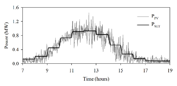
To evaluate the proposed control scheme for PV/HES system, the PV system output data and output power setpoint data for hourly power dispatch of PV source are necessary. Fig. 2 shows the average daily PPV profile for a 1.2 MW PV system which has been analyzed from the Malaysian historical radiation and temperature data in [24]. The average hourly solar radiation was preliminarily analyzed in Matlab by using statistics to represent the average one-day input data of a PV system. The data was then altered by adding random noise data in order to represent the real output of the considered PV system. The added random noise data were extracted based on the nominal Malaysian weather characteristic, in which the major intermittent clouds occurred during the middle of the day between 11 AM to 3 PM. To provide accurate PPV profile data, 5% losses of the power converter is also considered with MPPT operation taken into account.
Besides that, Fig. 2 also presents the PSET curve that was calculated from the hourly average of the PPV profile with 10% added mean absolute error (MAE) noise data to represent the forecast accuracy of the PV output forecasting model. The rate limiter is also applied to PSET to minimize the output power ramps of the PV system and prevents overshooting when PSET changes.
3.2 Modelling of BES system
The Li-ion battery was considered as BES because of its excellent features, such as high efficiency and high energy density. The battery model was developed based on a dynamic battery model, as described in [26]. The battery model is represented by the equations to describe the electrochemical behaviour of a battery in terms of the state of charge, terminal voltage, cell temperature and internal resistance. The formulated equations of the BES are described using Eq. 1 to Eq. 5, where VBat is the battery voltage (V), EBat,c and EBat,d are the battery electromotive force during charge and discharge (V). IBat is the battery current (A) and Rint is the battery internal resistance (Ω). Q is the cell battery capacity (Ah) and EO is battery open-circuit voltage (V). K is Polarisation resistance (Ω), i* is filtered current (A) and it is actual battery current (Ah). A is exponential zone voltage (V) and B is exponential zone time constant inverse (Ah-1)
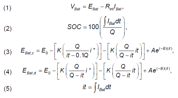
By combinations of the series and parallel battery cell, BES model can be constructed as follow:
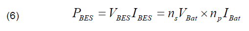
where ns is the number of cell in series and np is the number of cell in parallel, respectively. The number of cells in series and parallel determines total output terminal voltage and capacity or total size of a battery bank respectively. All of the parameters for the battery model can be approximated by using the manufacturer’s data following the procedures in [26]. For the battery model, there are several specific assumptions and limitations such as there is no self-discharge, the nominal capacity and internal resistance constant and there are no environmental considerations.
3.3 Modelling of UC
The electric double-layer capacitor (EDLC) is selected as a short term energy storage due to its advantages such as fast charge/discharge process, high power density, and extended lifetime. For the simulation studies, the EDLC model is developed based on the dynamic equivalent circuit, described in [2].
The mathematical model of dynamic EDLC consists of Stern and Tafel equations which relate to voltage, current and the available charge of the EDLC. The Tafel equation is used to calculate the self-discharge of EDLC and the Stern equation is used to calculate the voltage of the controlled voltage source. The Tafel and Stern equation is described as follows [17]:
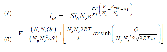
where Ns and Np are the numbers of series and parallel EDLC cells. Nc is the number of electrodes layers, Q is the electric charge (C), r is the molecular radius (m) and ε permittivity of the material. S is the interfacial area between electrodes and electrolyte (m2), R is the ideal gas constant, T is operating temperature (F), α is charge transfer coefficient, c is the molar concentration (molm-3), i0 is exchanged current density, F is Faraday constant, Vmax is surge voltage (V) and ΔV is over-potential voltage (V). The details of parameters and calculation are described in [27].
4.0 Fuzzy-Based Hourly Dispatch Control Strategy
A fuzzy logic controller is well-known as an effective technique to control various kinds of complex systems [28]. In the present study, a fuzzy controller is considered to control the operation of PV/HES in order to provide stable output power to the grid system. Fig. 3 shows the proposed fuzzy-based control scheme with hourly dispatch for a hybrid PV/HES system.
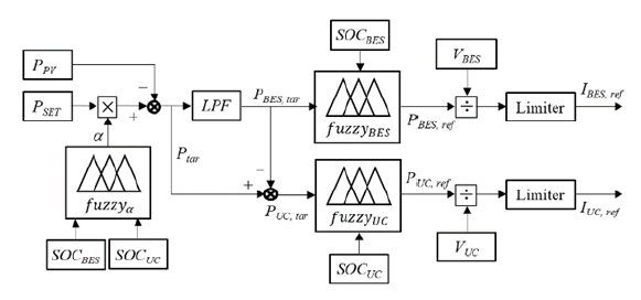
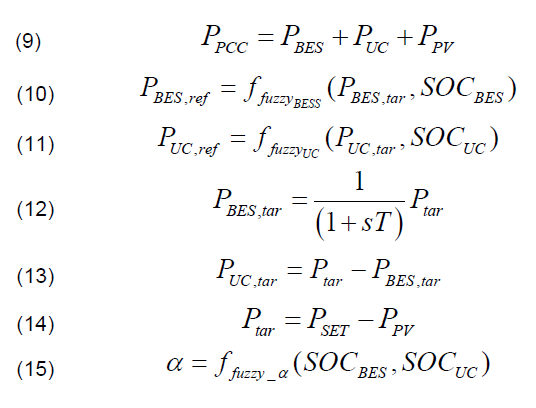
As shown in the figure, the fuzzy logic-based control scheme consists of two major layers. The first layer is the adjustment of power set-point level, PSET, in which fuzzyα adjusts the PSET of the PV output depending on the overall SOC level of BES and UC (SOCBES & SOCUC), respectively. The second layer is the adjustment of energy storage power dispatch, where fuzzyBES and fuzzyUC adjust the power dispatching of BES and UC depending on their SOC levels, respectively. As illustrated in Fig. 3, PPV and PSET are inputs of the control scheme and the deviation between PPV and PSET is a target power (Ptar) for the BES and UC to charge and discharge the power. Ptar is filtered using first order low pass filter (LPF) to ensure that the UC storage device compensates for sudden changes in the rapidly fluctuating PV output power while the BES storage device covers the long-term fluctuating PV output. The filtered outputs from LPF (PBES,tar & PUC,tar), SOCBES and SOCUC are used as inputs of fuzzyBES and fuzzyUC to regulate the reference for BES and UC (PBES,ref & PUC,ref) in order to dispatch the power to the PCC, respectively. So that the PV system output power is smoothed out. The control scheme in Fig. 3 can be formulated based on Equation (9)-(15).
4.1 Fuzzy logic-based hourly set-point control fuzzy_α
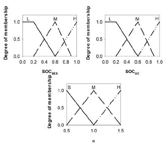
Fuzzy logic control for PSET adjustment, fuzzyα is designed to alter the PSET level based on SOCBES and SOCUC, respectively by applying the coefficient (α) to the PSET level. The coefficient greatly determines the charging and discharging levels of BES and UC, respectively. During the low level of SOCBES and SOCUC, the fuzzyα adjusts the α to decrease the PSET level which means that more power and energy needs to be charged by the BES and UC, respectively. Whereas during the high level of SOCBES and SOCUC, the fuzzyα regulates the α to increase the PSET level which means that more energy is required to be compensated by the BES and UC, respectively. Fig. 4 shows the membership function of fuzzyα. The input membership function contains three levels; low (L), medium (M) and high (H), while the output membership function contains three levels; small (S), medium (M) and high (H). The fuzzy rules are described as follows:
1. If SOCBES is L or SOCUC is L then output is S
2. If SOCBES is M or SOCUC is M then output is M
3. If SOCBES is H or SOCUC is H then output is H
4.2 Fuzzy logic-based BES power control (fuzzyBES)
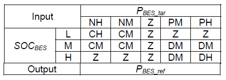
Fuzzy logic controller for BES, fuzzyBES consists of two inputs and one output as shown in Fig. 3. The fuzzyBES is designed to adjust the PBES,tar according to the SOCBES level. The input and output membership functions of the fuzzyBES are as shown in Fig. 5, respectively. Five levels of PBES,tar membership function are considered; NH, NM, Z, PM and PH where N stands for Negative, Z for zero, P for positive, M for medium and H for high to perform a compromise between the accuracy of the power control and its complexity. While three levels of SOCBES membership functions are considered; low (L), medium (M) and high (H) to accommodate the needs of the proposed strategy. The low level and high level of SOCBES represent the energy reserve to avoid the over-charging and over-discharging of BES while the medium level is used to compensate for the long-term PV power fluctuation around the PBES,tar. PBES,ref represents the output of fuzzyBES membership function. Five levels are considered for positive and negative power reference; CH, CM, Z, DM and DH where C stands for a charge, Z for zero, D for discharge, M for medium and H for high. The fuzzy rules of fuzzyBES are designed to prevent the BES from energy depletion. The rules are described in Table 1.
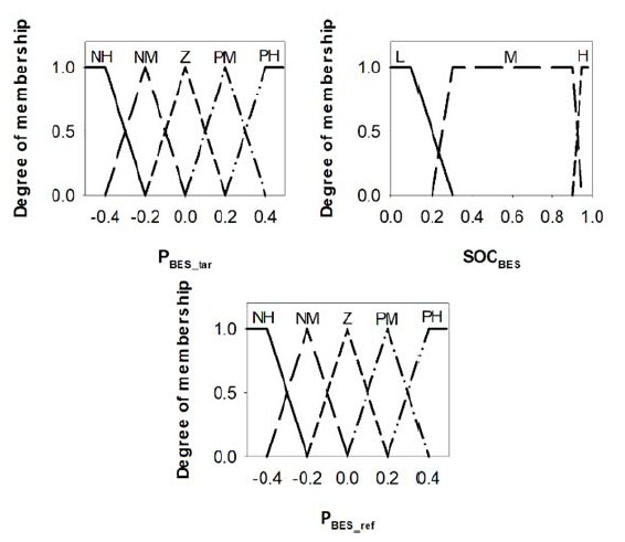
Table 1. Fuzzy rules of fuzzyBES
4.3 Fuzzy logic-based UC power control (fuzzyUC)
Fuzzy logic controller for UC, fuzzyUC consists of two inputs and one output as shown in Fig. 3. PUC,tar and SOCUC are chosen as input of the fuzzyUC. The fuzzyUC regulates PUC,tar according to SOCUC level to ensure the sustainability of UC energy. The output from the controller is PUC,ref that will be used by the UC to charge/discharge its power. The input and output membership function of the controllers are as shown in Fig. 6, respectively.
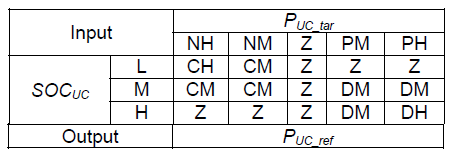
Five levels of PUC,tar membership function are considered; NH, NM, Z, PM and PH where N stands for Negative, Z for zero, P for positive, M for medium and H for high, while three levels of SOCUC membership function are considered; low (L), medium (M) and high (H) as illustrated in Fig. 6. The low level and high level of SOCUC represent the energy saturation to keep the UC in the safe operation during charging and discharging. The medium level of UC is used to compensate for the short-term PV power fluctuation. For the PUC,ref, five levels are considered; CH, CM, Z, DM and DH where C stands for the charge, Z for zero, D for discharge, M for medium and H for high. The fuzzy rules of fuzzyUC are described in Table 2.
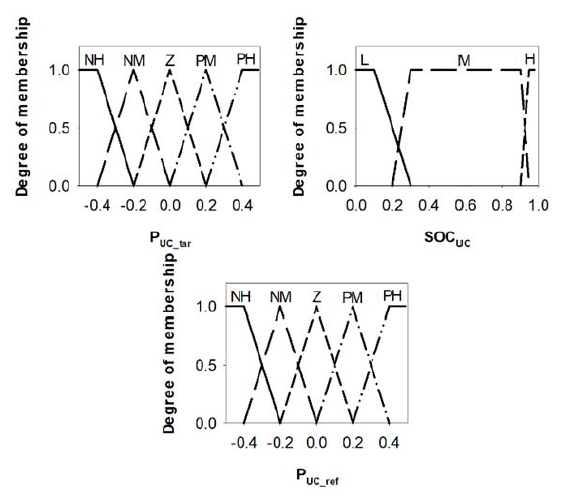
Table 2. Fuzzy rules of fuzzyUC
5.0 Results and discussion
In this paper, the effectiveness of the proposed control scheme in order to provide an adequate smoothing of PV output power fluctuations is examined through the simulation. The performance evaluation of the proposed control scheme based on the cases the study results are discussed in Section 5.1 and then the evaluation results of the proposed control scheme using actual five-day PV output power data is discussed in Section 5.2.
5.1 Result of analysis based on the difference of initial SOC of BES and UC
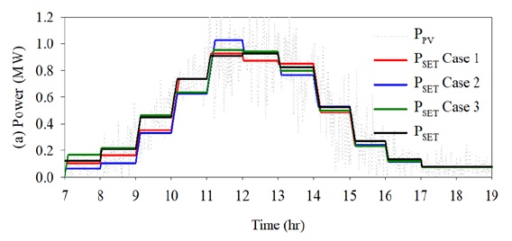
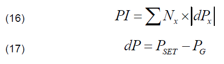
The proposed fuzzy-based control scheme was initially evaluated by three case studies of the initial SOC level of HES. In these cases, the initial SOCBES and SOCUC were set to 100%, 50% and 10%, respectively. Fig. 7 provides the result of PSET adjustment for different case studies, while Fig. 8 shows the simulation result of the output power, SOCBES and SOCUC profiles, for three different cases studied, respectively. The following describes the conditions of each case study.
5.1.1 Case 1: SOC set at 100%
For case 1, the initial SOCBES and SOCUC were set to 90% which is the highest SOC level for the BES and UC. In this case, during the high SOC level of BES and UC, the proposed controller efficiently adjusts the hourly set point, PSET level as illustrated in Fig. 7. As indicated in Fig. 7, the PSET was increased to switch the BES and UC device to discharge mode. So, the BES and UC can discharge more power to the PCC in order to maintain their SOC level at the nominal SOC state, as shown in Fig. 8(a). From Figure 8(b) and (c), the SOCBES and SOCUC can be efficiently restored to their nominal capacity state after several hours of operation without the need for additional energy storage capacity. Also, the maximum PPV can be transferred to the grid system.
5.1.2 Case 2: SOC set at 10%
For case 2, the initial SOCBES and SOCUC were set to 10% and which is the lowest SOC level for the BES and UC, respectively. In this case, during the low SOC level of BES and UC, the proposed control scheme adjusts to reduce the PSET level, as shown in Fig. 7. So that, the BES and UC can be changed to charge mode in order to restore their energy at the nominal SOC state. As indicated in Fig. 8(a)-(c), more PPV is used to charge and discharge HES instead of the PPV injected into the grid system. From the simulation results, it was verified that the proposed control scheme efficiently managed the BES and UC to restore their energy at the nominal SOC state.
5.1.3 Case 3: SOC set at 50%
For case 3, the initial SOCBES and SOCUC were set to 50%, which was considered as a nominal SOC level of BES and UC. In this case, the PSET level remains unchanged throughout the process, as demonstrated in Fig. 7. This is due to the energy balance of the BES and UC which enables BES and UC to charge and discharge the energy during the mitigation process, as shown in Fig. 8(b) and (c). The figures also show the SOCBES and SOCUC remain stable until the end of the simulation.
In addition, the comparison of the PV/HES performance with and without the proposed control scheme also is discussed in the present study. In this case, the performance index, PI of the PV/BES system was firstly determined using the following equations [29]:
where, dP is the deviation of the total power transfer to the grid, PG and the PSET . PG is the power measured at the PCC bus. Nx is the number of dP. In this case, the acceptable dP is set to ±10% of the PV system capacity, as suggested in [30].
The result of PI is illustrated in Fig. 9. From Fig. 9(a), it can be observed that without the proposed control scheme, a large unacceptable power fluctuation has occurred. The result shows that without the proposed control scheme, the total of unacceptable dP is found to be approximately 20% of the total occurrences. Also, only 50% of PG meets the PSET level during the dispatching process. However, for the case using the proposed control scheme, the unacceptable deviations greatly decreased to less than 1%, as shown in Fig. 9(b). The result also shows 90% of the PG meets the PSET level during the dispatching process.
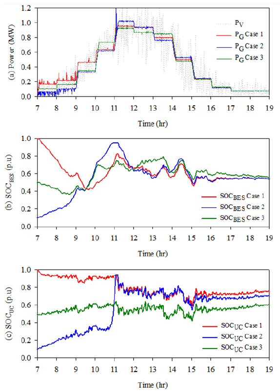
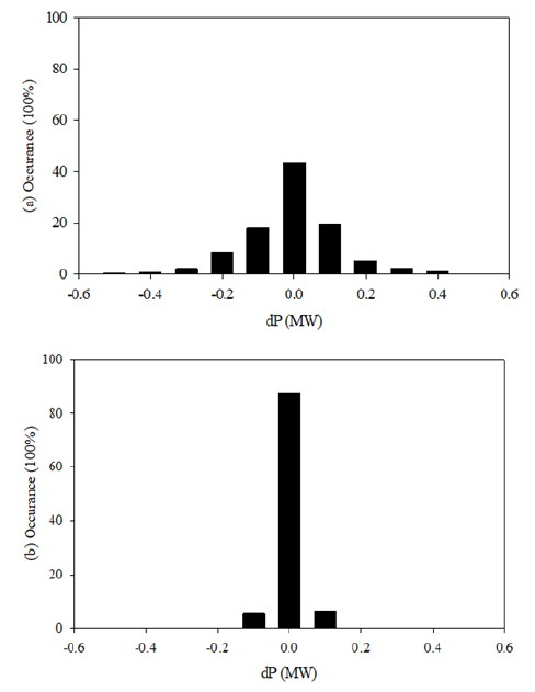
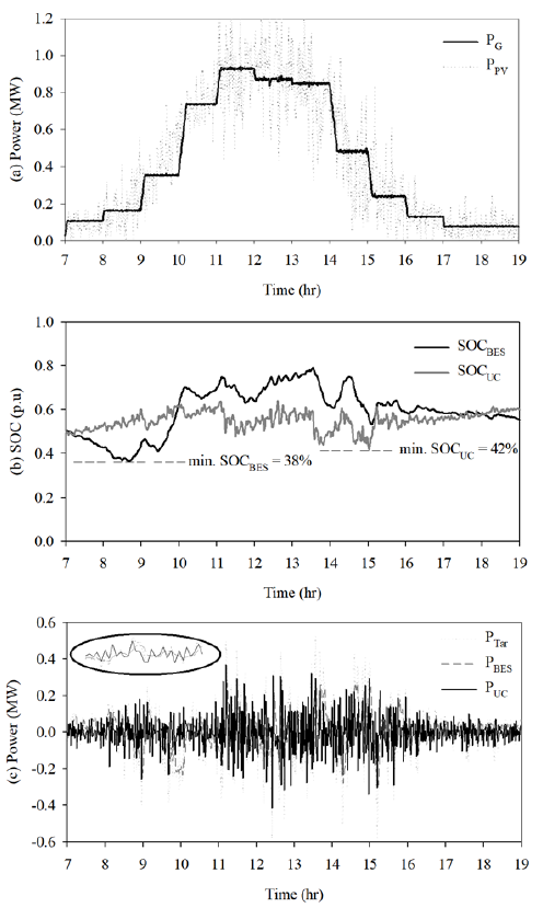
Fig. 10 demonstrates the simulation results of the system performance during the nominal condition, in which the initial SOCBES and SOCUC were set to 50%. The dispatching performance of the PV/HES system is shown in Fig. 12(a) whereas the corresponding SOC profile and power profile of BES and UC are shown in Fig. 10(b) and (c), respectively. As indicated in Fig. 10(a) and (b), PSET can be tracked perfectly while keeping the SOCBES and SOCUC level at the desired operational constraints. From Fig. 10(a), the power fluctuation of the PV system is successfully smoothed out and dispatched out to the utility grid on an hourly basis. Consequently, Fig. 10(b) shows that SOCBES and SOCUC are regulated and varied within the acceptable operational range, which is within 38%-75% and 42%-60%, respectively throughout the process. The power compensated by BES and UC during the smoothing process are illustrated in Fig. 10(c) and it is observed that BES and UC are used to mitigate long-term and short term output fluctuationns, respectively.
5.2 Simulation results of the proposed controller applied to actual PV output data
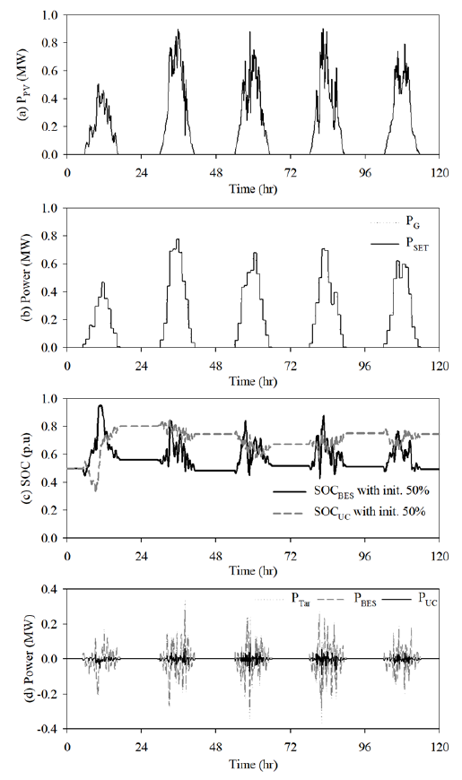
The proposed control scheme is further validated using actual PV system output data. The purpose of the simulation is to evaluate the robustness of the proposed control scheme in actual circumstances. In this case, typical five minute resolution data for five days are collected from a 3 kWp rooftop PV system [30]. The data magnitude was scaled 4 times to represent a 1.2 MW size of PV system for the comparison purpose, as shown in Fig. 11(a). From the figure, it can be seen the impact of intermittent clouds on PV system output causes power fluctuation injected into the utility grid. Overall, the fluctuated PPV normally occurs between 11 AM to 3 PM. During such a situation, it may cause problems and instability of grid operation such as frequency deviation, voltage rise and dip, voltage deviations, prolonged power fluctuation, etc. These power fluctuation problems can be mitigated using the proposed control scheme, as shown in Fig. 11(b). From the figure, it can be seen the fluctuated PPV are successfully smoothed out and dispatched to the utility grid on an hourly basis. During the power dispatching process, the SOCBES and SOCUC operational constraints are kept at the acceptable operational limits, as illustrated in Fig. 11(c). The power compensated by BES and UC throughout the process is shown in Fig. 11(d).
6.0 Conclusion
This paper proposed a fuzzy logic-based control scheme for hourly dispatch of fluctuated PV system output using the HES system. The HES comprises UC and BES energy storage devices which are used to mitigate the long-term and short-term output fluctuation of the PV system. The control scheme was developed to ensure the safe operation of the storage system while continuously providing energy support for power fluctuation mitigation. Initially, the simulation results based on several initial SOC conditions have demonstrated the effectiveness of the proposed control scheme. The results show using the proposed control scheme the unacceptable power fluctuations of the PV system was successfully reduced from 20% to less than 1%. The results also show the proposed control scheme efficiently managed the SOCBES and SOCUC within its operational limit throughout the process. It can be seen that during the nominal initial SOC case, the SOCBES and SOCUC were measured between 38%-75% and 42%-60%, respectively. Finally, the robustness of the proposed system was evaluated using five days of actual PV system output data. The evaluation result shows that a proposed control scheme is able to manage the output fluctuation of a PV system over 5 days of operation without any failure of energy support from the HES. In conclusion, since a simple fuzzy controller was used in the proposed control scheme, it can be easy to implement in real-time applications, particularly for renewable energy-based power fluctuation mitigation strategies. Also, it is suggested that further experimental validation of the proposed control scheme is needed to verify its performance in the real application.
Acknowledgements The authors would like to acknowledge Universiti Malaysia Terengganu for the financial support of this research. This research is supported by Universiti Malaysia Terengganu under the UMT TAPE-RG grant, vot. no. 55221.
REFERENCES
[1] S. Shivashankar, S. Mekhilef, H. Mokhlis, and M. Karimi, “Mitigating methods of power fluctuation of photovoltaic (PV) sources – A review,” Renew. Sustain. Energy Rev., vol. 59, pp. 1170–1184, Jun. 2016, doi: 10.1016/j.rser.2016.01.059.
[2] T. T. Trung, S. J. Ahn, J. H. Choi, S. Il Go, and S. R. Nam, “Real-time wavelet-based coordinated control of hybrid energy storage systems for denoising and flattening wind power output,” Energies, vol. 7, no. 10, pp. 6620–6644, Oct. 2014, doi: 10.3390/en7106620.
[3] J. Marcos, L. Marroyo, E. Lorenzo, and M. García, “Smoothing of PV power fluctuations by geographical dispersion,” Prog. Photovoltaics Res. Appl., vol. 20, no. 2, pp. 226–237, Mar. 2012, doi: 10.1002/pip.1127.
[4] M. Lave, J. Kleissl, and E. Arias-Castro, “High-frequency irradiance fluctuations and geographic smoothing,” Solar Energy, vol. 86, no. 8. Pergamon, pp. 2190–2199, Aug. 01, 2012, doi: 10.1016/j.solener.2011.06.031.
[5] T. E. Hoff and R. Perez, “Quantifying PV power Output Variability,” Sol. Energy, vol. 84, no. 10, pp. 1782–1793, Oct. 2010, doi: 10.1016/j.solener.2010.07.003.
[6] M. Z. Daud, A. Mohamed, and M. A. Hannan, “A novel coordinated control strategy considering power smoothing for a hybrid photovoltaic/battery energy storage system,” J. Cent. South Univ., vol. 23, no. 2, pp. 394–404, Feb. 2016, doi: 10.1007/s11771-016-3084-2.
[7] P. P. Zarina, S. Mishra, and P. C. Sekhar, “Exploring frequency control capability of a PV system in a hybrid PV-rotating machine-without storage system,” Int. J. Electr. Power Energy Syst., vol. 60, pp. 258–267, Sep. 2014, doi: 10.1016/j.ijepes.2014.02.033.
[8] R. Tonkoski, L. A. C. Lopes, and T. H. M. El-Fouly, “Coordinated active power curtailment of grid connected PV inverters for overvoltage prevention,” IEEE Trans. Sustain. Energy, vol. 2, no. 2, pp. 139–147, Apr. 2011, doi: 10.1109/TSTE.2010.2098483.
[9] M. A. Jusoh and M. Z. Daud, “Particle swarm optimisationbased optimal photovoltaic system of hourly output power dispatch using Lithium-ion batteries,” J. Mech. Eng. Sci., vol. 11, no. 3, pp. 2780–2793, Sep. 2017, doi: 10.15282/jmes.11.3.2017.1.0252.
[10] M. Datta, T. Senjyu, A. Yona, T. Funabashi, and C. H. Kim, “A frequency-control approach by photovoltaic generator in a PVdiesel hybrid power system,” IEEE Trans. Energy Convers., vol. 26, no. 2, pp. 559–571, Jun. 2011, doi: 10.1109/TEC.2010.2089688.
[11] M. A. Jusoh and M. Z. Daud, “Control strategy of a gridconnected photovoltaic with battery energy storage system for hourly power dispatch,” Int. J. Power Electron. Drive Syst., vol. 8, no. 4, pp. 1830–1840, Dec. 2017, doi: 10.11591/ijpeds.v8i4.pp1830-1840.
[12] J. S. Park, T. Katagi, S. Yamamoto, and T. Hashimoto, “Operation control of photovoltaic/diesel hybrid generating system considering fluctuation of solar radiation,” Sol. Energy Mater. Sol. Cells, vol. 67, no. 1–4, pp. 535–542, Mar. 2001, doi: 10.1016/S0927-0248(00)00325-1.
[13] M. Z. Daud, A. Mohamed, M. A. Hannan, “A review of the intergration of Energy Stroage Systems (ESS) for utility grid support,” PRZEGLAD ELEKTROTECHNICZNY, vol. Jan. 2011, vol. 10a/2012, pp. 185–191
[14] B. Boumediene, A. Smaili, T. Allaoui, A. Berkani and F. Marignett, “Backstepping control strategy for multi-source energy system based flying capacitor inverter and PMSG,” in PRZEGLAD ELEKTROTECHNICZNY, vol. 3/2021, pp. 21Proceedings, 2007, pp. 21-29, doi:10.15199/48.2021.03.04.
[15] C Sourkounis, B Ni, F Richter, ” Comparison of energy storage management methods to smooth power fluctuations of wind parks”, PRZEGLAD ELEKTROTECHNICZNY, vol. 10/2009, pp.196-200, doi:
[16] X. Tan, Q. Li, and H. Wang, “Advances and trends of energy storage technology in Microgrid,” Int. J. Electr. Power Energy Syst., vol. 44, no. 1, pp. 179–191, Jan. 2013, doi: 10.1016/j.ijepes.2012.07.015.
[17] M. Sechilariu, B. Wang, and F. Locment, “Building integrated photovoltaic system with energy storage and smart grid communication,” IEEE Trans. Ind. Electron., vol. 60, no. 4, pp. 1607–1618, 2013, doi: 10.1109/TIE.2012.2222852.
[18] N. S. Jayalakshmi, D. N. Gaonkar, J. V. Kumar, and R. P. Karthik, “Battery-ultracapacitor storage devices to mitigate power fluctuations for grid connected PV system,” Mar. 2016, doi: 10.1109/INDICON.2015.7443500.
[19] Y. Ye, R. Sharma, and D. Shi, “Adaptive control of hybrid Ultracapacitor-Battery storage system for PV output smoothing,” in American Society of Mechanical Engineers, Power Division (Publication) POWER, Feb. 2013, vol. 2, doi: 10.1115/POWER2013-98210.
[20] M. E. Glavin and W. G. Hurley, “Optimisation of a photovoltaic battery ultracapacitor hybrid energy storage system,” Sol. Energy, vol. 86, no. 10, pp. 3009–3020, Oct. 2012, doi: 10.1016/j.solener.2012.07.005.
[21] X. Feng, H. B. Gooi, and S. X. Chen, “Hybrid energy storage with multimode fuzzy power Allocator for PV systems,” IEEE Trans. Sustain. Energy, vol. 5, no. 2, pp. 389–397, Apr. 2014, doi: 10.1109/TSTE.2013.2290543.
[22] T. H. Kwan and X. Wu, “Maximum power point tracking using a variable antecedent fuzzy logic controller,” Sol. Energy, vol. 137, pp. 189–200, Nov. 2016, doi: 10.1016/j.solener.2016.08.008.
[23] P. García, J. P. Torreglosa, L. M. Fernández, and F. Jurado, “Optimal energy management system for stand-alone wind turbine/photovoltaic/ hydrogen/battery hybrid system with supervisory control based on fuzzy logic,” Int. J. Hydrogen Energy, vol. 38, no. 33, pp. 14146–14158, Nov. 2013, doi: 10.1016/j.ijhydene.2013.08.106.
[24] J. Cao and X. Lin, “Study of hourly and daily solar irradiation forecast using diagonal recurrent wavelet neural networks,” Energy Convers. Manag., vol. 49, no. 6, pp. 1396–1406, Jun. 2008, doi: 10.1016/j.enconman.2007.12.030.
[25] M. Z. Daud, A. Mohamed, A. A. Ibrahim, and M. A. Hannan, “Heuristic optimization of state-of-charge feedback controller parameters for output power dispatch of hybrid photovoltaic/battery energy storage system,” Meas. J. Int. Meas. Confed., vol. 49, no. 1, pp. 15–25, Mar. 2014, doi: 10.1016/j.measurement.2013.11.032.
[26] O. Tremblay and L. A. Dessaint, “Experimental validation of a battery dynamic model for EV applications,” World Electr. Veh. J., vol. 3, no. 2, pp. 289–298, Jun. 2009, doi: 10.3390/wevj3020289.
[27] “Implement generic supercapacitor model – Simulink.” https://www.mathworks.com/help/physmod/sps/powersys/ref/supercapacitor.html (accessed May 19, 2021).
[28] L. Suganthi, S. Iniyan, and A. A. Samuel, “Applications of fuzzy logic in renewable energy systems – A review,” Renew. Sustain. Energy Rev., vol. 48, pp. 585–607, 2015, doi: 10.1016/j.rser.2015.04.037.
[29] S. Teleke, M. E. Baran, A. Q. Huang, S. Bhattacharya, and L. Anderson, “Control strategies for battery energy storage for wind farm dispatching,” IEEE Trans. Energy Convers., vol. 24, no. 3, pp. 725–732, 2009, doi: 10.1109/TEC.2009.2016000.
[30] M. Z. Daud, A. Mohamed, and M. A. Hannan, “An improved control method of battery energy storage system for hourly dispatch of photovoltaic power sources,” Energy Convers. Manag., vol. 73, pp. 256–270, Sep. 2013, doi: 10.1016/j.enconman.2013.04.013.
Authors: Mohd Afifi Jusoh, Renewable Energy and Power Research Interest Group (REPRIG), Eastern Corridor Renewable Energy SIG, Faculty of Ocean Engineering Technology and Informatics, Universiti Malaysia Terengganu, 21030 Kuala Nerus, Terengganu Malaysia. Email: mohd.afifi.jusoh@gmail.com;
Assoc. Prof. Ts. Dr. Muhamad Zalani Daud (Corresponding Author), Renewable Energy and Power Research Interest Group (REPRIG), Eastern Corridor Renewable Energy SIG, Faculty of Ocean Engineering Technology and Informatics, Universiti Malaysia Terengganu, 21030 Kuala Nerus, Terengganu Malaysia. Email: zalani@umt.edu.my
Prof. Ts. Dr. Mohd Zamri Ibrahim, Renewable Energy and Power Research Interest Group (REPRIG), Eastern Corridor Renewable Energy SIG, Faculty of Ocean Engineering Technology and Informatics, Universiti Malaysia Terengganu, 21030 Kuala Nerus, Terengganu Malaysia. Email: zam@umt.edu.my
Source & Publisher Item Identifier: PRZEGLĄD ELEKTROTECHNICZNY, ISSN 0033-2097, R. 98 NR 1/2022. doi:10.15199/48.2022.01.02
