Published by Gideon UMOH1, Chinedu OBE2, Cosmas OGBUKA2, George EKPO3, Emeka OBE2,
Department of Electrical Engineering, Maritime Academy of Nigeria, Oron, Akwa-Ibom State, Nigeria(1),
Department of Electrical Engineering, University of Nigeria, Nsukka, Enugu State, Nigeria(2)
Department of Electrical and Electronic Engineering, Akwa Ibom State Polytechnic, Ikot Osurua, Nigeria(3)
Abstract. The direct-phase variable (DPV) model of a five-phase synchronous reluctance motor (SRM) for direct-on-line starting is presented. The model eliminates the dependence of inductances on rotor position. Machine performance characteristics namely vector potential, speed, flux linkage and current were monitored under different conditions. The DPV model was simulated in MATLAB/Simulink while a finite element model (FEM) was simulated using ANSYS Maxwell FEA software for comparison and validation. Very close similarities in obtained results justify the DPV model.
Streszczenie. Przedstawiono moddel pięciofazowego reluktancyjnego silnika synchronicznego wykorzystywanego do startu on-line. Zbadano potencjał wektorowy, szybkość, strumień rozproszony i prąd w różnych warunkach pracy. (DPV model i analiza pracy pięciofazowego synchronicznego silnika reluktancyjnego do bezpośredniego startu on-line) .
Keywords: direct-on-line (DOL), direct-phase variable (DPV), finite element model (FEM), five-phase synchronous reluctance motor (SRM)
Słowa kluczowe: silnik reluktancyjny, silnik pięciofazowy, silnik synchroniczny.
Introduction
The conventional starting method in most industrial processes utilizing the induction motor are the direct-on-line starting, star-delta starting and the auto-transformer starting, which have served the industries for several years [1,2]. Owing to the high cost of utilization of the power electronics drives systems, advancement in the area of electric machine design can minimize the use of the power electronics drives, with minimal or no compromise to the machine performance especially where variable speed operation is not desired. Considering the most common and easily used starting method; the direct-on-line staring, the machine windings can be modelled to have a similar waveform as its supply voltage. The squirrel cage placed on the rotor has been the backbone of direct-on-line starting methods. The synchronous reluctance motor (SRM) can also be modelled to harness these advantages by using a cage rotor. The SRM has a conventional stator similar to that of the induction motor (IM), but utilizes reluctance torque for energy conversion, and can be modelled as a simplest form of a salient pole synchronous motor without any field winding [3,4]. Earlier design improvements of the SRM seeks to improve saliency ratio of the rotor [5,6,7,8].
For the synchronous machine, the stator inductances depend on the rotor position, as the transformation of the machine variables to the d-q frame to remove these dependencies is adopted by many authors especially for the multi-phase machines [9]. The unnecessary encumbrances associated with the d-q modelling are readily eliminated using the DPV model [10]. The phase variable model has remained an essential model in predicting the machine performance during faults and unbalanced conditions [4, 11,12]. The phase variable model takes into account the stator phase windings and the rotor d-q windings of the machine, representing the machine equations in terms of the machine variables, as compared to the direct-quadrature (d-q) axis transformation of which the stator phases are transformed to a fictitious axis of references. The combination of the Winding Function (WF) model and the direct-phase variable model has been proven to give accurate result that can be compared with the Finite Element Method (FEM) [4]. The finite element model [4, 13,14,15,16,17,18,19,20,21], has helped in electric machine design optimization, and in reducing design error to a minimum. The use of the multi-phase machines has assisted in torque production without an increase in the copper loss of the machine by the utilization of additional harmonics with the fundamental component, and helps in the optimization of the air-gap magneto motive force (MMF) [11,22]. The advantage of the 5-phase over 3-phase machine is that torque pulsation especially for SRM is highly reduced [23,24,25].
The present study is aimed at developing a direct-phase variable (DPV) model of a five-phase synchronous reluctance motor for direct-on-line starting. The developed model will be subjected to performance test during normal, loaded, fault and unbalanced conditions considering the following performance characteristics; vector potential, speed, flux linkage and current. The suitability of the developed DPV model will be validated by comparing the results with results obtained using the FEM which is widely considered as near ideal.
Phase variable model of five-phase synchronous reluctance motor
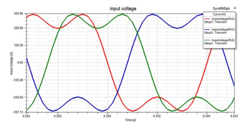
A five-phase (5-ph), cage rotor synchronous reluctance motor having 4-pole, 40 slots is modelled for direct-on-line starting. The supply is a 5ph voltage from a converter, without any form of control, modelled to have a similar waveform as in Fig. 1 (i.e. a sinusoidal waveform of the (first and the third harmonics) to reduce torque ripples.
The voltage equation for a five-phase SRM is given in [4] as.


where θr is the rotor position. The rotor inductances are function of the rotor position. and V are the machine current and voltage matrices and are given in (3) and (4) respectively. The inductance matrix is given in (5).
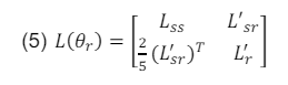
where,
where Lss is the stator inductance matrix, L’r is the rotor inductance matrix referred to the stator, L’sr is the mutual inductance matrix between the stator and the rotor referred to the stator, L’lkq is the rotor q-axis leakage inductance referred to the stator and L’lkd is the rotor d-axis leakage inductance referred to the stator.

where R is the resistance matrix. The expression for the electromagnetic torque is given in (10).

Where Is , Ir , J , p and Tl are the stator current matrix, rotor current matrix, inertia constant, number of machine poles and load torque respectively.
The Stator resistance can be calculated from (14),

Where: σc, vxl and Ac are the conductivity, total volume of conductor per phase and the conductor cross-sectional area.
Inductance Calculation
The motor structure showing the cross-section of the five-phase SRM is shown in Fig. 2. On the basis of this cross-section, the configuration of the full-pitched double layer winding is tabulated in Table 1.

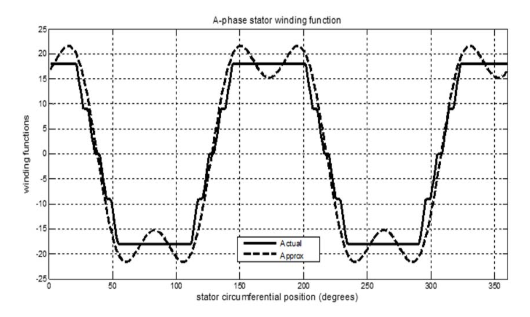
The winding function can also be approximated using the fundamental and the third harmonic components to represent the different phases with regard to their respective phase shifts.
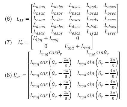
The different phase windings for any of the phases will be of the form shown in (15).
where, ∝ is 0, – 2π/5, – 4π/5, 4π/5, 2π/5 for A, B, C, D and E phases respectively, while Φs is the stator circumferential position.
Fig. 3 shows the winding functions plot against the stator circumferential position of phase A of the machine using the winding function method and its approximation from utilizing only the fundamental and the third harmonic components to represent the actual winding function. Similar plot can be made with the necessary phase shift.
Table 1. 5-ph 4-pole winding of ACEBD double layer winding configuration

The expression for the calculation of stator inductances is presented in (16).
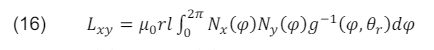
where Nx(φ) nd Ny(φ) are the winding functions of phase X and Y respectively and φ is the stator circumferential position, g-1(φ,θr) is the inverse air gap function which is a function of the stator circumferential position (φ) and the rotor position (θr), while ݈ is the axial length of the air gap of the machine, r is the radius to the mean of the air gap and µ0 is the permittivity of free space. The inverse air-gap function including the third harmonic component is given in (17).

where,

where ga the main air gap length, gb is the inter-polar slot space and β is the ratio of pole arc to pole pitch.
From a generalized equation of inductances, (16) yields:

where the expression for and are given in (21) and (22) as:


where A = 2θr; B = 2θr–θ1; C = 2θr – θ2; D = 2θr + θ2; E = 2θr + θ1;
The mutual inductances between the stator and the rotor are given in (8). If desired, the q-axis and the d-axis magnetizing inductances can be obtained from the stator inductance values, and are given in (23) and (24) respectively.

where,

Simulation of the Dynamic Process
The design parameters of the 5-ph SRM are given in Table 2. The developed machine was monitored for performance characteristics at synchronism, loading and during fault and loss of synchronism.
The machine speed characteristics are simulated using MATLAB/SIMULINK for the DPV and ANSYS Maxwell software for the FEM. A load torque value of 50N-m introduced at 0.98 seconds, representing a continuous running duty cycle for the motor, and subsequently a loss of e-phase fault while on load, lasting for 0.5 seconds was created at 1.7 seconds in both simulations. A ramp load torque spanning from 50 Nm to 110 Nm within 0.5 seconds was introduced at 3.0 seconds to determine the load carrying capacity of the models. The combined load torque is shown in Fig. 4.
Table 2. 5-Phase SRM machine dimensions and circuit parameters
Table 3. Settling time and loss of synchronism for speed characteristics

Table 4. Speed performance characteristics


The speed characteristics for the DPV and FEM are presented in Fig. 5. Greater settling time is observed in the FEM model. At synchronism, a settling time of 0.887 seconds is recorded for DPV as compared to a settling time of 0.887 seconds for FEM. The settling time for the speed during different conditions of synchronism, loading, fault and subsequent rectification of fault are tabulated in Table 3.
The speed transient characteristics at start showed the least percentage value rise of 8.9 % about the synchronous speed for FEM as compared to a percentage value rise of 15.27 % for the DPV. The speed transient characteristics at loading showed a least percentage rise of 2.27% and 2.13% for FEM and DPV respectively. At fault a least percentage transient rise values of 4.47 % and 6.07% is observed for DPV and FEM respectively. When the loss of e-phase fault was cleared, the least transient percentage rise value of 2.93% and 6.27% are recorded for DPV and FEM respectively. A lower value of difference in percentage rise were observed on loading, fault and when the fault was cleared. The Speed transient performance characteristics at start, loading, fault and when the fault is cleared are tabulated in Table 4.
The Speed characteristics plots for FEM showing transient at start, loss of phase fault and loss of synchronism are presented in Fig. 6, Fig. 7, and Fig. 8 respectively.

The flux linkage at synchronism, loading fault and when the fault was cleared was monitored with the FEM and the DPV and are tabulated in Table 5. The plot of the a-phase flux linkage during synchronism for FEM and DPV are presented in Fig. 9. A 1.95% drop is observed in the FEM as compared to 0.69% drop as recorded in the DPV. A 22.7% drop is recorded for FEM during fault as compared to 2.53 % drop for the DPV. The current characteristics for the five phases are similar since a symmetrical winding and loading is employed, the A-phase stator current characteristics are presented for both models in Fig. 10 for FEM and DPV, and tabulated in Table 7.


A high transient rise is observed in the FEM at start, with a value of 111.3 A as compared to a value rise of 87.73 A for DPV as shown in Table 6.
At synchronism, a value of 16.11A and 16.56 A is recorded for FEM and DPV respectively. On loading, a current rise of 19.16A and 16.56A was observed for FEM and DPV respectively. The highest variation is observed during fault with a value of 4.02% as compared to at synchronism, loading and when the fault was cleared.
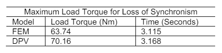
The torque performance of both models at loss of synchronism are tabulated in Table 7. At loss of synchronism due to the introduction of ramp load at 3.0 seconds, spanning between 50Nm and 110Nm a carrying capacity of 63.74Nm and 70.16 Nm are recorded for FEM and DPV respectively.
Table 5. Flux linkage performance characteristics
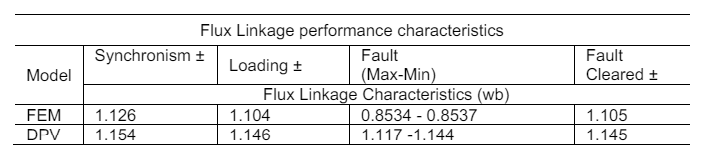
Table 6. Stator A-Phase Current performance characteristics

Table 7. Maximum load torque
Conclusion
The developed DPV model of five-phase synchronous reluctance motor (SRM) for direct-on-line starting has been analysed using MATLAB/Simulink and validated using ANSYS Maxwell. The performance characteristics of the vector potential, speed, flux linkage, a-phase current and the load carrying capacity were considered. The machine was modelled with full-pitched stator winding configuration with the developed model accounting for the third harmonics of the Air-gap MMF.
The developed DPV model and the FEM were monitored and compared for performance characteristics at start, on loading, during loss of e-phase fault, and loss of synchronism due to loading. Apart from a higher transient rise at start, observed with the FEM, both models show similar performance characteristics of the parameters for the considered conditions. A highest variance of 4.02 % rise in current is observed during fault between the models while the load accommodating capacity of 70.16 N-m at 3.168 seconds for the DPV and 63.74 at 3.115 seconds for the FEM were recorded.
With these competitive results when compared to the FEM which is nearly ideal, it is sufficient to conclude that the developed DPV model can satisfactorily give adequate information on the analysis of 5-phase SRM and can as well be extended to other multi-phase machines.
REFERENCES
[1] Aree P., Precise Analytical Formula for Starting Time Calculation of Medium- and High-Voltage Induction Motors under Conventional Starter Methods, Electrical Engineering, 100 (2018),1195–1203
[2] Kocman S., Orsag P., Pecinka P., Simulation of Start-Up Behaviour of Induction Motor with Direct Online Connection, Advances in Electrical and Electronic Engineering, 15 (2017), No.5, 754-762
[3] Ogbuka C., Nwosu C., Umoh G., A New Cross-Saturated Torque Model of Highly Utilized Synchronous Reluctance Machine, Archives of Electrical Engineering, 67 (2018), No. 1 109–121
[4] Obe E., Binder A., Direct-Phase-Variable Model of a Synchronous Reluctance Motor Including All Slot and Winding Harmonics, Energy Conversion and Management, 52 (2011), No. 1, 284-291
[5] Stipetic S., Zarko D., Cavar N., Adjustment of Rated Current and Power Factor in a Synchronous Reluctance Motor Optimally Designed for Maximum Saliency Ratio, IEEE Transactions on Industry Applications, 56(2020), No. 3, 2481 – 2490
[6] Jurca F., Inte R., Martis C., Optimal Rotor Design of Novel Outer Rotor Reluctance Synchronous Machine, Electrical Engineering, 102 (2020), 107–116
[7] Chai W., Zhao W., Kwon B., Optimal Design of Wound Field Synchronous Reluctance Machines to Improve Torque by Increasing the Saliency Ratio, IEEE Transactions on Magnetics, 53 (2017), No. 11
[8] V. Hrabovcová V, Makyš P, Rafajdus P, Šebest M., Improved Barriers Rotor of the Reluctance Synchronous Motor, Electrical Engineering, 99 (2017), 1325–1335
[9] Alves de Souza S., Suemitsu W., Five-Phase PermanentMagnet Synchronous Motor, IEEE Latin America Transactions, 15 (2017), No. 4, 639 – 645
[10] Umoh G., Ogbuka C., Obe E., Modelling and Analysis of FivePhase Permanent Magnet Synchronous Motor in Machine Variables, Przegląd Elektrotechniczny, 96 (2020), No.1, 87-92
[11] Umoh G., Obe E., Five-Phase Synchronous Reluctance Motor: a Better Alternative to The Three-Phase Synchronous Reluctance Motor, ICEPENG 2015 International Conference Nsukka, (2015), 56- 61
[12] Umoh G., Obe E., Analysis of Five-Phase Synchronous Reluctance Motor under Loaded and Faulted Conditions, ICEPENG 2015 International Conference Nsukka, (2005), 37-43
[13] Mahmoudi A., Kahourzade S., Rahim N., Ping H., Improvement to Performance of Solid-Rotor Ringed Line-Start Axial-Flux Permanent-Magnet Motor, Progress in Electromagnetics Research, 124 (2012), 383-404
[14] Torkaman H., Afjei E., Gorgani A., Faraji N., Karim H., Arbab N., External Rotor SRM with High Torque per Volume: Design, Analysis, and Experiments, Electrical Engineering, 95 (2013), 393–401
[15] Duan Y., Ionel I., A Review of Recent Developments in Electrical Machine Design Optimization Methods with a Permanent-Magnet Synchronous Motor Benchmark Study, IEEE Transactions on Industry Applications, 49 (2013), No.3,1268 – 1275
[16] Tahi S., Ibtiouen R., Bounekhla M., Design Optimization of Two Synchronous Reluctance Machine Structure with Maximized Torque and Power Factor, Progress in Electromagnetics Research, 35 (2011), 369-387
[17] Krüttgen C., Steentjes S., Glehn G., Hameyer K., Parametric Homogenized Model for Inclusion of Eddy Currents and Hysteresis in 2-D Finite-Element Simulation of Electrical Machines, IEEE Transactions on Magnetics. 53 (2017), No. 6
[18] Zhao W., Xing F., Wang X., Lipo T., Kwon B., Design and Analysis of a Novel PM-Assisted Synchronous Reluctance Machine with Axially Integrated Magnets by the Finite-Element Method, IEEE Transactions on Magnetics, 53 (2017), No. 6
[19] Tiegna H., Bellara A., Amara Y., Barakat G., Analytical modeling of the open-circuit magnetic field in axial flux permanent-magnet machines with semi-closed slots, IEEE Transactions on Magnetics, 48 (2012), No. 3, 1212-1226
[20] Azizi H., Vahedi A., Sensitivity Analysis and Optimum Design for the Stator of Synchronous Reluctance Machine using the Coupled Finite and Taguchi Method, Turkish Journal of Electrical and Computer Sciences, 23 (2015), 17 – 27
[21] Nekoubin A, Soltani J, Dowlatshahi M (2020) Comparative Analysis of Three-Phase and Five-Phase Permanent-Magnet Motor Based on Finite Element Method, Journal of Electrical Engineering & Technology, 15 (2020), 1705–1712
[22] Perreira L., Scharlau C., Pereira L., Haffner S., Influence of Saturation on the Airgap Induction Waveform of Five-Phase Induction Machines, IEEE Transactions on Energy Conversion, 27 (2012), No. 1, 29-41
[23] Parsa L., Toliyat H., Goodarzi A., Five-phase Interior Permanent-Magnet Motors with Low Torque Pulsation, IEEE Transactions on Industry Applications, 43 (2007), No. 1 40–46
[24] Baek J., Bonthu S., Choi S., Design of Five-Phase Permanent Magnet Assisted Synchronous Reluctance Motor for Low Output Torque Ripple Applications, IET Electric Power Applications, 10 (2016), No. 5, 339 – 346
[25] Lin C., Hwang C., High Performances Design of a Six-Phase Synchronous Reluctance Motor Using Multi-Objective Optimization with Altered Bee Colony Optimization and Taguchi Method, Energies, 11 (2018), 1-14
Authors: Engr. Dr. Gideon Umoh, Department of Electrical Engineering, Maritime Academy of Nigeria, Oron, Akwa-Ibom State, Nigeria, E-mail: umoh.gideon@gmail.com; Engr. Chinedu Obe, Department of Electrical Engineering, University of Nigeria, Nsukka, Enugu State, Nigeria, E-mail: chinedu.obe@unn.edu.ng, Engr. Dr. Cosmas Ogbuka (Corresponding Author), Department of Electrical Engineering, University of Nigeria, Nsukka, Enugu State, Nigeria, E-mail: cosmas.ogbuka@unn.edu.ng; George Ekpo, Email: georgeekpo@gmail.com, Department of Electrical and Electronic Engineering, Akwa Ibom State Polytechnic, Ikot Osurua, Nigeria; Engr. Prof. Emeka Obe, Department of Electrical Engineering, University of Nigeria, Nsukka, Enugu State, Nigeria, E-mail: simon.obe@unn.edu.ng
Source & Publisher Item Identifier: PRZEGLĄD ELEKTROTECHNICZNY, ISSN 0033-2097, R. 97 NR 1/2021. doi:10.15199/48.2021.01.05
