Published by Ľubomír BEŇA1, Paweł KUT2,
Rzeszow University of Technology, Faculty of Electrical and Computer Engineering (1)
Rzeszow University of Technology, Faculty of Civil and Environmental Engineering and Architecture (2)
Abstract. The large number of wind farms in the power system makes it possible to use them in the process of voltage regulation in the nodes to which they were connected. The regulation possibilities depend on the generators in which the wind farm has been equipped. Currently, Doubly-Fed Induction Generators are the most commonly used ones, which have wide possibilities of reactive power and voltage control at the wind farm connection point. The article presents an analysis of the connection of a wind farm consisting of wind turbines equipped with DFIG generators to the power system for the possibility of voltage regulation. Simulations were carried out using PowerWorld Simulation software.
Streszczenie. Duża liczba farm wiatrowych w systemie elektroenergetycznym stwarza możliwość wykorzystania ich w procesie regulacji napięcia w węzłach do których zostały przyłączone. Możliwości regulacyjne zależą od generatorów w jakie zostały wyposażone elektrownie wiatrowe. Obecnie najczęściej znajdują zastosowanie generatory asynchroniczne dwustronnie zasilane, które posiadają szerokie możliwości regulacji mocy biernej, a co za tym idzie napięcia w punkcie przyłączenia farmy wiatrowej. W artykule przedstawiono analizę przyłączenia farmy wiatrowej, składającej się z elektrowni wiatrowych wyposażonych w generatory asynchroniczne dwustronnie zasilane do systemu elektroenergetycznego pod kątem możliwości regulacji napięcia. Symulacje zostały przeprowadzone z wykorzystaniem oprogramowania PowerWorld Simulator. Farmy wiatrowe w procesie regulacji napicia w systemie energetycznym
Keywords: wind farm, voltage, reactive power, power system
Słowa kluczowe: farma wiatrowa, napięcie, moc bierna, system elektroenergetyczny
Introduction
Renewable energy sources are now considered to be the most prospective energy sector. Solar energy and its derivatives are a free and inexhaustible source of energy [1]. Thanks to the rapid development of technologies in the field of renewable energy, the efficiency of generating units increase year by year, while the investment cost decrease. Increasing the share of renewable energy sources in the energy systems of the Member States is now a priority in the European Union energy policy. Funds earmarked for this purpose are to accelerate the development of renewable energy sources and enable diversification of fuels and gradual independence from conventional fuels. The current climate package assumes an increase in renewable energy sources share in the European Union to 20% by 2020. In 2016, the share of renewable energy in final energy consumption was 17% for the European Union [2]. Another target will be to increase energy production in renewable energy sources to 27% in 2030 [3].
According to the data of the Polish Energy Regulatory Office [4], in the Polish national power system, the total installed capacity in renewable energy sources at 30.05.2018 amounted to 8 584,552 MW, and the power in installations using wind energy was 5 874,778, which is 68,43% of the total installed power in renewable energy. One can notice the slowdown in the development of wind energy in Poland as a result of the Wind Farm Investment Act [5,6]. In 2016, the installed capacity in wind sources was 5 807,416 MW, so within 2 years the power increased by only 67,362 MW.
The high installed capacity in wind farms makes it possible to use them for the process of voltage regulation in the power system nodes. Thanks to the use of wind farms with large reactive power control options, the transmission system operator can use wind farm to maintain the required voltage level at the connection point [7]. The use of wind farms in the reactive power control process also allows limiting voltage fluctuations resulting from the stochastic nature of wind and reducing power losses in the internal network of the wind farm and in the network to which it is connected. The connection of wind farms to the power system does not increase the voltage distortion at the connection point [8].
Voltage in the power system
To ensure correct operation of the power system, it is necessary to balance the active and reactive power. One of the basic parameters affecting the quality of electricity is frequency and voltage. Maintaining a constant frequency requires balancing of active power, while a proper balancing of reactive power is associated with maintaining the correct voltage in the system nodes.
The demand of receiving nodes for reactive power is around 42%. The remaining 58% are own needs of the network, which include: longitudinal losses in lines – 21%, longitudinal losses in transformers – 20%, generators demand – 9% and losses in network transformers – 8% [9].
Constant changes in the system load make it necessary to adjust the voltage levels in the power system nodes. Voltage deviations below the rated value are caused by [10]:
• voltage drops in medium and low voltage lines and in transformers;
• too low voltage on the medium voltage side in station 110/MV, resulting from fault conditions. Voltage deviations above the rated value are caused by:
• positive value of longitudinal voltage loss induced by capacitive reactive power flows;
• too high voltage on medium voltage substation bus and MV/LV transformers in abnormal operating conditions.
The value of voltage drop in overhead lines and transformers depends primarily on the part of the longitudinal voltage loss, which is dependent on the reactive component of the current:
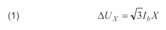
where: Ib – reactive component of the current.
The longitudinal part of the voltage loss depends on the active current component is much smaller:
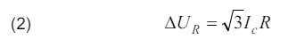
where: Ic – active component of the current.
This is due to the fact that the value of the overhead line reactance is much higher compared to the resistance. The longitudinal voltage loss increases the value of the voltage at the end of the line when capacitive and less at inductive. For this reason, voltage regulation is closely related to the reactive power regulation.
Wind turbines equipped with an Doubly-Fed Induction Generator
Wind turbines equipped with DFIG (Doubly-Fed Induction Generator) generators have a wide range of active and reactive power regulation, which is why they currently belong to the most commonly used generators in wind energy sector. DFIG generators allow to obtain better quality of electricity compared to other generators used in wind farms. They provide active suppression of voltage and power oscillations as well as current and voltage harmonics.
Doubly-Fed Induction Generators are equipped with an energy electronic converter connected to the rotor circuit, thanks to which it is possible to transmit energy in both directions: from and to the rotor [11]. DFIG generators enable operation at both super-synchronous and sub-synchronous speeds. In the case of super-synchronous operation, the energy flows from the rotor to the grid, while during the work with the sub-synchronous speed, the energy flows from the stator to the rotor.
Figure 1 shows the characteristics of the Vestas V90 – 3 MW wind turbine equipped with Doubly-Fed Induction Generator, on which the area of permissible operating conditions is marked.

Wind turbines Vestas V90 – 3 MW enable operation in the constant power factor mode in the range of 0,98cap – 0,96ind. It is possible to work with a different power factor, but with a reduction in the value of active power generated. When generator is connected in a triangle, the maximum reactive power generated is 1500 kvar, while for star connection 750 kvar.
Analysis of the possibility of using a wind farm in voltage regulation
Simulations were carried out using the PowerWorld Simulator program. PowerWorld Simulator enables analysis of active and reactive power distribution as well as voltage level analysis in power system nodes.
The analysis of the wind farm’s impact on the voltage level in the power network was carried out for a wind farm consisting of 10 wind turbines Vestas V90 – 3 MW (Fig.2, EW1-EW10). The 30 MW wind farm was connected to the 110 kV network.
Figure 2 shows the diagram of the internal network. The wind farm has a three radial lines connected to the main supply point located on the wind farm. In the case of a radial structure, damage to the cable stops the transmission of energy from wind turbines located behind the damaged part of the internal network. The ring topology is characterized by greater reliability, but requires higher investment costs.

The diagram of the analyzed fragment of the power system, modelled in the PowerWorld Simulator is shown in figure 3. The wind farm was connected at node 13.

Table 1 presents the values of active and reactive power of a wind farm for which simulations have been carried out. Reactive power was determined based on the simulation of the internal network of the wind farm.
Table 1. The values of active and reactive power in simulations
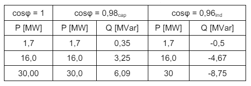
Figure 4 shows the results of the simulation depending on the power factor of wind farms.

The regulations possibilities of a wind farm consisting of wind turbines equipped with Doubly-Fed Induction Generators, create the possibility of improving voltage conditions in the node to which the wind farm is connected and in neighbouring nodes. In case the voltage at the connection point is lower than required, the wind farm may became a source of reactive power, which will increase the voltage in the node. In the analyzed case, when wind turbines operate with a power factor of cosφ = 0,98cap, the voltage at the connection point (node 13), compared to work with the power factor cosφ = 1, increased by 0,9% for a wind farm working with 30 MW. In the case of wind turbines operating with a power factor cosφ = 0,96ind, it is possible to obtain a constant voltage in the nodes, despite increasing the active power generation. Figure 5 shows relation between voltage and reactive power.

Figure 6 shows the power losses in the analyzed fragment of the power system depending on the active power for the analyzed values of the power factor cosφ.

In the case of wind turbines with cosφ = 0,98cap, the losses of active power in the network to which the farm is connected are reduced as compared to the work with the power factor cosφ = 1.
Table 2 shows the calculated coefficient kU,P, which is a measure of how the voltage in the network nodes changes depending on the active power generated. The higher value of this coefficient means the greater difference between the voltage in the node depending on the generated active power. The coefficient kU,P is defined by the formula:
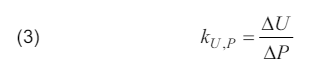
where: ∆U – voltage difference, ∆P – difference between maximum and minimum active power generated by wind farm.
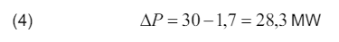
Table 2. Values of the coefficient kU,P
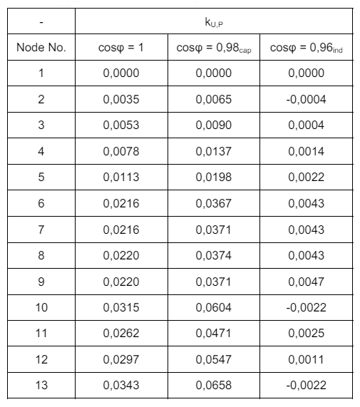
As can be seen from the above results, increasing the reactive power output increases the voltage at all nodes of the network.
Summary
Wind farms, thanks to their regulation capabilities, can be used by the transmission system operator to regulate the voltage in the node to which it was connected and in neighbouring nodes.
The ability to work with reactive power capacitive and inductive by wind turbines with Doubly-Fed Induction Generators allows to maintain a constant voltage at the connection point despite increasing the active power generation and increasing or decreasing the voltage in the node.
The connection of wind farms close to the recipients also positively influences the level of active power losses in the network, which decreases when the wind farm work with higher active power.
REFERENCES
[1] Proszak-Miąsik D., Bukowska M., Nowak K., Rabczak S., Astronomical and meteorological conditions of a solar system operation, Iop Conf Ser-Mat Sci., 245, (2017)
[2] Statistical data on energy from renewable sources, Eurostat
[3] http://www.cire.pl/item,96778,1,0,0,0,0,0,ke-do-2030-r-wzrostefektywnoscienergetycznej-o-30-proc.html, Dostęp. 01.12.2018
[4] http://www.ure.gov.pl/pl/rynki-energii/energiaelektryczna/odnawialne-zrodla-ener/potencjal-krajowyoze/5753,Moc-zainstalowana -MW.html, dostęp 01.12.2018
[5] Ustawa z dnia 20 maja 2016 r. o inwestycjach w zakresie elektrowni wiatrowych
[6] Ustawa z dnia 7 czerwca 2018 roku. o zmianie ustawy o odnawialnych źródłach energii oraz niektórych innych ustaw
[7] Pijarski P., Kacejko P., Wancerz M., Gryniewicz-Jaworska M., Układ sterowania mocą bierną farmy wiatrowej wykorzystujący możliwości regulacyjne przekształtników, dławika zaczepowego oraz pojemność kabla zasilającego farmę, Przegląd Elektrotechniczny, 92 (2016), nr. 8, 44-47
[8] Gała M., Praca turbin wiatrowych w systemie elektroenergetycznym oraz ich wpływ na jakość energii elektrycznej, Przegląd Elektrotechniczny, 93 (2017), nr.6, 37-40
[9] Kot A., Bilans I zapotrzebowanie mocy biernej w Krajowym Systemie Elektroenergetycznym, Acta Energetica, 1 (2013), nr.14, 68-71
[10] Praca zbiorowa, Poradnik inżyniera elektryka, WNT, 2011
[11] Klucznik J, Udział farm wiatrowych w regulacji napięcia w sieci dystrybucyjnej, Acta Energetica, 1 (2010), nr. 3, 39-39
[12] Grządzielski I., Sposoby kompensacji mocy biernej, prezentacja Międzynarodowe Targi Energetyki Expopower, Poznań 2010.
Authors: dr hab. inż. Ľubomír Beňa, prof. PRz, Rzeszow University of Technology, Faculty of Electrical and Computer Engineering, Department of Power Electronics and Power Engineering, ul. Wincentego Pola 2, 35-959 Rzeszów, E-mail: lbena@prz.edu.pl; mgr inż. Paweł Kut, Rzeszow University of Technology, Faculty of Civil and Environmental Engineering and Architecture, Department of Heat Engineering and Air Conditioning, Al. Powstańców Warszawy 6, 35-959 Rzeszów, E-mail: p.kut@prz.edu.pl.
Source & Publisher Item Identifier: PRZEGLĄD ELEKTROTECHNICZNY, ISSN 0033-2097, R. 95 NR 8/2019. doi:10.15199/48.2019.08.33
