Published by Elbrus AHMEDOV1, Nadir ALİYEV2, Seymur SADIQOV3,Azerbaijan State Oil and Industry University (1, 2) ORCID: 1. 0000-0003-3348-7946; 2. 0009-0001-3165-1493
Abstract. The present article delves into strategies aimed at augmenting the impulse electrical strength of the insulation in high-voltage transformer windings. The research focal point centers on an authentically produced autotransformer boasting a 330 kV voltage rating, serving as the object of inquiry. The investigation systematically probes the influence of coil winding methods on both the electrical robustness of the winding and the insulation between the discs. To assess the insulation reliability inherent in a series-wound contra shield, adhering to the transformer method, a laboratory examination was conducted by the IEC 60076-3 standard, specifically designed to evaluate the impact induced by a direct lightning strike. Subsequently, a simulation model was constructed within the VLN program to ascertain the voltage distribution in the unconventional interleaved winding approach of an alternating transformer. A lightning impulse voltage test was executed, pinpointing critical junctures. A comparative analysis was then undertaken to discern the disparities between the results obtained. Remarkably, in contrast to the contra shield method featuring wound windings, the interleaved winding technique exhibited superior impulse electrical strength and, concurrently, proved to be cost-effective.
Streszczenie. W artykule omówiono strategie mające na celu zwiększenie udarowej wytrzymałości elektrycznej izolacji w uzwojeniach transformatorów wysokiego napięcia. Główny punkt badań skupia się na autentycznie wyprodukowanym autotransformatorze o napięciu znamionowym 330 kV, będącym przedmiotem badań. W badaniach systematycznie badany jest wpływ metod nawijania cewek zarówno na wytrzymałość elektryczną uzwojenia, jak i izolację pomiędzy tarczami. Aby ocenić niezawodność izolacji właściwą dla przeciwosłony szeregowo uzwojonej, stosującej metodę transformatorową, przeprowadzono badania laboratoryjne zgodnie z normą IEC 60076-3, specjalnie zaprojektowane do oceny uderzenia wywołanego bezpośrednim uderzeniem pioruna. Następnie w programie VLN zbudowano model symulacyjny w celu ustalenia rozkładu napięcia w niekonwencjonalnym podejściu do uzwojenia przeplatanego transformatora przemiennego. Przeprowadzono test napięcia impulsowego pioruna, identyfikując krytyczne punkty. Następnie przeprowadzono analizę porównawczą, aby dostrzec rozbieżności pomiędzy uzyskanymi wynikami. Co ciekawe, w przeciwieństwie do metody przeciwosłonowej obejmującej uzwojenia uzwojone, technika uzwojenia przeplatanego wykazała doskonałą wytrzymałość elektryczną impulsu, a jednocześnie okazała się opłacalna. (Zwiększanie udarowej wytrzymałości elektrycznej izolacji uzwojeń transformatorów wysokiego napięcia)
Keywords: high-voltage transformer, winding methods, lightning impulse voltage, increasing electrical strength.
Słowa kluczowe: transformator wysokiego napięcia, metody uzwojenia, napięcie udarowe piorunowe, zwiększanie wytrzymałości elektrycznej.
Introduction
High-voltage transformers are one of the most important elements of electrical energy transmission and supply systems. For a transformer to operate reliably for a long time, the electrical strength of its insulation must withstand both operating and impulse voltages. The causes of damage to the insulation of power transformers are electric and magnetic fields, gas and hydrodynamic processes, temperature, and various external factors such as humidity, pollution, etc., which are consequences of complex physical and chemical processes occurring under their influence [1–4]. The main condition for the development of damage is that the action of the electric field in the insulating gap exceeds its electrical strength.
Transformers may be subject to factory test voltage after manufacture or impulse voltage (lightning or short circuit voltage) during operation. The purpose of a power transformer surge voltage insulation test is to check the ability of the transformer insulation to withstand high voltage surges that may occur during a fault or overvoltage. The testing process involves applying a voltage pulse of a certain shape, duration, and amplitude to the transformer winding, followed by measuring the characteristics of the resulting voltage and current [5–8]. However, testing the insulation of a power transformer with a pulse voltage can give both positive and negative results. If the surge voltage is too high or the test is not carried out correctly, there is a risk of damage to the transformer. This can lead to expensive repairs or even the complete failure of the transformer. Therefore, the impulse electrical strength of winding insulation is one of the main factors ensuring the reliability and durability of transformers. Defects within the insulation.
The purpose of the presented work is to study ways to increase the pulse electrical resistance of the insulation of the windings of high-voltage transformers.
As mentioned, when high-voltage transformers are exposed to pulsed voltage, several electrophysical processes can occur in the winding and insulation of the turns. Such processes include [9–11].
• charging and discharging a capacitor: when a pulse voltage is applied to the winding of a transformer, the turns behave like capacitors and are charged and discharged depending on the duration and frequency of the pulse. This can cause a strong electric field to appear in the winding insulation and lead to partial discharge and breakdown;
• electromagnetic induction-pulse voltage creates an electromagnetic field in the transformer winding, which can cause eddy currents in the wires and local heating of the insulation, causing breakdown; heating of the dielectric: a strong electric field can cause heating of the dielectric in the insulation, thermal degradation, and subsequent breakdown;
• electromechanical stresses: impulse voltage can cause mechanical stresses in both the winding and the insulation, which can lead to deformation and cracking of the insulation.
Problem setting
Under the influence of impulse voltage, transition processes develop in the transformer winding, in the adjacent winding elements – in the insulation between the windings or disks, and also between the grounded parts of the transformer – the magnetic conductor and the coil. To see the transition processes, let’s look at the equivalent electrical circuit of one phase (for example, high voltage) of the transformer winding (Fig.1). To study the electromagnetic processes taking place here, let’s introduce elements connected in series to the coil, for example, windings and coils. Each branch of the circuit consists of the inductance ΔL of the element, its capacitance to ground ΔC, and the capacitance ΔK between the elements.
Fig.1. Replacement circuit of the transformer
When transformer windings are exposed to atmospheric pulse voltages, the current flowing through the capacitances of the windings is comparable to the currents flowing through the inductances (and even significantly exceeds them at the initial stage) due to the high rate of change in voltage before the pulse. It is possible to increase the impulse electrical strength of the insulation of high-voltage transformer windings using various methods:
• correct choice of insulating material: The selection of insulating materials significantly impacts the impulse dielectric strength of transformer insulation. Insulating materials with high breakdown voltage, low dielectric loss, and good thermal conductivity can enhance the impulse electrical reliability of the system. The most commonly used insulation materials include cellulose paper, pressboard, and epoxy resin. Currently, composite materials based on polymer nanocomposites with high pulse electrical resistance have also been developed [14, 15].
• insulation processing technology: The manufacturing process of transformer insulation significantly affects the impulse dielectric strength of the insulation system. Techniques such as vacuum impregnation and partial discharge detection can be employed to improve the quality of the insulation system. Additionally, the use of high-quality insulation materials, proper drying methods, and precise temperature control during the manufacturing process can help enhance the impulse resistance of the insulation system.
• design optimization: Optimizing the transformer winding design and insulation system allows for an increase in the dielectric strength of the pulse. For instance, the impulse dielectric strength of an insulation system can be elevated by methods such as increasing the thickness of the insulation layers, improving the quality of the connection between the layers, and ensuring uniform voltage distribution. Moreover, the use of alternative winding methods makes it possible to reduce the electric field strength inside, thereby increasing the electrical strength of the pulse.
Let’s examine the impact of the winding method on the electrical strength of the insulation in a high-voltage transformer. The subject of our investigation is a newly developed single-phase autotransformer with a voltage rating of 330 kV, manufactured by ATEF. The relevant parameters are outlined in Table 1.
Table 1 High voltage transformer parameters
The winding configuration employed for this transformer wound using the contra shield method. The circuit is augmented with supplementary elements designed to enhance the relatively uniform distribution of electrical voltage across the windings and the pulsed electrical insulation resistance.
In this particular arrangement, shielding electrical cardboard (depicted in Fig.2.,1) and an additional shielding coil (illustrated in Fig. 2.,3) are systematically positioned between the disks. The specifications of the structural components comprising the high-voltage winding are detailed in Table 2.
Table 2. Structural parameters of the high-voltage winding of the transformer 330 kV
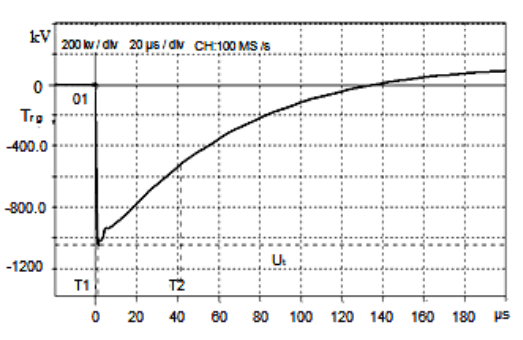
To determine the reliability of the transformer insulation, a test was carried out using a pulse voltage generator (BREMER Transformatoren GmbH-GEOS) according to the IEC60076-3 standard [16-19]. Tests were carried out under lightning impulse voltage (LI) and lightning impulse chopped (LIC). The parameters of the lightning pulse supplied to the high-voltage winding of the transformer are in Fig. 3.The transformer was successfully tested and the insulation electrical strength was determined to be at the required level [20-22].
The advantageous attribute of the winding technique illustrated in Figure 2 lies in its technological simplicity and enhanced temporal efficiency during coil preparation. Nevertheless, a notable drawback of this method manifests in including a shielding coil, necessitating the utilization of supplementary materials, notably cardboard and copper. Furthermore, the incorporation of a shielded winding results in a diminution of coil turns, attributed to spatial constraints, and introduces challenges in attaining resilience against prescribed lightning test voltages commensurate with voltage classes of 400 kV and above.
As is commonly understood, a disk-type winding comprises a configuration of turns wound in the radial direction. Notably, the number of turns on a given disk may exhibit variability. However, the augmentation of turn count, concomitant with an enlargement of radial dimensions, induces an escalation in the potential difference across the terminal turn of the coil. Concurrently, the inter-disk spacing gives rise to inductance and capacitance, thereby engendering variable high voltage levels within discrete circuit segments during lightning impulse testing. This variability in voltage distribution may, consequently, lead to insulation breakdown, a curtailed operational lifespan for the transformer in its entirety, and, in certain instances, even precipitate transformer failure during testing.
We conducted a comparative analysis of various winding methods, namely the contra shield and interleaved techniques, intending to enhance the electrical strength of transformer winding insulation by achieving a uniform electric field between turns. The consideration of interleaved methods aims to diminish the strength and nonuniformity of the electric field between disks without the need for additional shielding winding. The alteration of primary and secondary turn directions during coil winding in the interleaved manner facilitates a more even distribution of the electric field between disks, thereby mitigating the risk of breakdown attributed to partial discharge. This results in the uniform distribution of alternating voltage across transformer disks, maintaining a constant voltage between adjacent turns. Nevertheless, it is essential to acknowledge the capacitance effect, which may lead to voltage surges and consequently higher voltages between windings at the loop’s termination.
We employed the VLN program to assess the effectiveness of the proposed Interleaved methods against different overvoltage’s and test voltages [23]. With the VLN program, transformer testing can be simulated at any voltage. Furthermore, the VLN program enables the measurement of potential differences between windings, between windings and grounded components, and simultaneously between specific points on turns (disks) through the application of a lightning impulse voltage. Utilizing these parameters, reports can be generated, allowing for the determination of the insulation resistance of the transformer windings to pulse voltages.
Fig.4.a, shows the contra shield winding method of the real transformer winding, and Fig.5.b, shows the proposed interleaved winding method.
Fig.5 depicts the actual 330-kV transformer, while Fig.6 illustrates the simulation outcomes of the lightning voltage impact on the proposed transformer, which features windings wound using the interleaved method. Each curve in both figures (Figure 5 and Figure 6) represents the voltage and its distribution in the form of a pulse wave, respectively, affecting the gap between individual discs. Given that the high-voltage winding of the transformer receives input from its central part, the voltage’s impact on the spacing of the discs above and below that point is identical. For simplicity, the simulation results are presented solely for the lower half of the winding.
Table 3. Voltages occurring between the disks of a real 330 kV transformer.
Table 4. Voltages occurring between the disks in the winding wound using the interleaved method of the transformer.
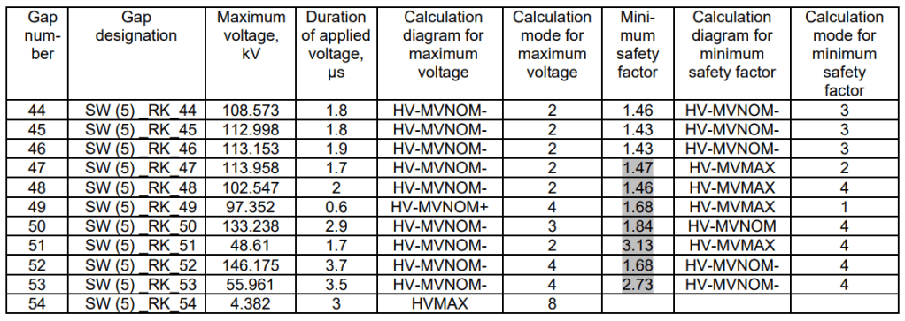
Table 3 presents simulated voltage values occurring between the discs of the 330 kV actual transformer, while Table 4 details the voltages in the windings of the interleaved transformer. These values were computed using the VLN program. The tables also include parameters like maximum voltage between the disks, duration, minimum safety factor, and others. The tables exclusively provide parameters for critical intervals. Through an analysis of the obtained values, it was concluded that intervals 48-53 (Tables 3 and 4), situated closer to the high-voltage input section, are critical points.
A comparative assessment of parameters in these tables reveals that the insulation resistance against impulse electric voltages in the winding of windings is notably high for both methods. However, when considering the safety factor, the interleaved winding exhibits superior safety indicators compared to windings employing the contra shield method. Consequently, in the interleaved winding, the minimum safety factor attains a higher value due to a relatively more evenly distributed electric field between the disks. As a result, the application of the interleaved winding method in high-voltage transformer windings yields more effective results.
Conclusions
The study aimed to investigate the impact of the winding method employed in the high-voltage winding of a 330 kV transformer on its impulse electrical strength. Lightning impulse electrical voltage, in accordance with the IEC60076-3 standard, was applied to assess the insulation’s electrical strength. To enhance the impulse electrical strength of the transformer’s insulation and achieve uniformity in the electric field between windings and disks, a comparative analysis of simulated and experimental results was conducted using the VLN program. This analysis considered winding methods employing contra shield and interleaved techniques. While both winding methods exhibited high resistance to impulse electric voltages during winding, a safety factor-based assessment revealed superior safety indicators for windings employing the interleaved method compared to those wound using the contra shield method. Based on the results of the analysis, it was determined that the impulse electrical strength of the insulation during winding with the interleaved method has a higher value than that of the contra shield winding method. Moreover, the interleaved method eliminates the need for an additional shielding winding, preventing additional material loss. Simultaneously, it facilitates a further increase in the impulse electrical strength of the insulation for 330 kV and higher voltage transformers.
REFERENCES
[1]. M. Popov, L. van der Sluis, R.P.P. Smeets, Evaluation of surge-transferred overvoltages in distribution transformers, Electric Power Syst. Res. 78 (2008) 441–449.
[2]. Elbrus Ahmedov, Sona Rzayeva, Nigar Ganıyeva, Elshad Safiyev. Improving the lightning resistance of high-voltage overhead power lines. Przeglad Elektrotechniczny, Vol 2023, №11, Page.121-126, 2023; ISSN: 0033-2097, R.99NR 6/2023, DOI:10.15199/48.2023.11.21
[3]. S.P. Balaji, S. Usa, Life estimation of transformer insulation under repeated impulses, in IEEE 1st International Conference on Condition Assessment Techniques in Electrical Systems (CATCON), Jadavpur University, Kolkata, India, 2013.
[4]. S.Okabe, Voltage-time and voltage-number characteristics of insulation elements with an oil-filled transformer in EHV & UHV classes, IEEE Trans. Dielectr. Electr. Insul. 13 (1) (2006).
[5]. P.Tuethong, P.Yutthagowith, A. Kunakorn. Effective Simulation Approach for Lightning Impulse Voltage Tests of Reactor and Transformer Windings. Energies 2020, 13(20), 5399; https://doi.org/10.3390/en13205399.
[6]. Kaveri Bhuyan, Saibal Chatterjee. Electric stresses on transformer winding insulation under standard and nonstandard impulse voltages. Electric Power Systems Research. Volume 123, June 2015, Pages 40-47. https://doi.org/10.1016/j.epsr.2015.01.019.
[7]. S. P. Balaji, I. P. M. Sheema, G. Krithika and S. Usa, “Effect of Repeated Impulses on Transformer Insulation,” in IEEE Transactions on Dielectrics and Electrical Insulation, vol. 18, no. 6, pp. 2069-2073, December 2011, doi: 10.1109/TDEI.2011.6118645.
[8]. Muzaffer Erdogan, Mehmet Kubilay Eker. Analysis of lightning impulse voltage distribution for a dry-type transformer using three different winding types. Electric Power Systems Research, Volume 188, 2020, 106527, ISSN 0378-7796, https://doi.org/10.1016/j.epsr.2020.106527.
[9]. A Mytnikov, A Lavrinovich, V Strugov and M Saqib. Development of impulse method for transformer winding condition control technology. IOP Conference Series: Materials Science and Engineering, Volume 1019, 14th International Forum on Strategic Technology (IFOST 2019) 14th-17th October 2019, Tomsk, Russian Federation. DOI 10.1088/1757-899X/1019/1/012024.
[10]. Bojan Trkulja, Ana Drandic, Viktor Milardic and Igor Žiger. Evaluation of Methodology for Lightning Impulse Voltage Distribution over High-Voltage Windings of Inductive Voltage Transformers. Energies 2021, 14(16), 5144. https://doi.org/10.3390/en14165144.
[11]. Juan M., Villanueva-Ramirez, Pablo Gómez, Richard T. Meyer. Optimized dielectric design of transformer windings under fast-front voltage pulses from power electronic converters. International Journal of Electrical Power and Energy Systems 129 (2021) 106849. https://doi.org/10.1016/j.ijepes.2021.106849.
[12]. M. A. Habib, M. A. G. Khan, M. K. Hossain, and S. A. Hossain, “Investigation of electric field intensity and degree of uniformity between electrodes under high voltage by Charge Simulation Method,” 2014 17th International Conference on Computer and Information Technology (ICCIT), Dhaka, Bangladesh, 2014, pp. 185-191, doi: 10.1109/ICCITechn.2014.7073140
[13]. Li, L., Huang, Z. and Yang, Y., 2020. The influence of electric field inhomogeneity on the repetitive performance of a coronastabilized switch. IEEE Access, 8, pp.195515-195527. 10.1109/ACCESS.2020.3033327.
[14]. Yu G, Cheng Y, Duan Z. Research Progress of Polymers/Inorganic Nanocomposite Electrical Insulating Materials. Molecules. 2022 Nov 15;27(22):7867. doi: 10.3390/molecules27227867. PMID: 36431967; PMCID: PMC9697380.
[15]. Mansour DA, Abdel-Gawad NMK, El Dein AZ, Ahmed HM, Darwish MMF, Lehtonen M. Recent Advances in Polymer Nanocomposites Based on Polyethylene and Polyvinylchloride for Power Cables. Materials (Basel). 2020 Dec 25;14(1):66. doi: 10.3390/ma14010066. PMID: 33375660; PMCID: PMC7795037.
[16]. IEEE Standard. 4 IEEE Standard for High-voltage Testing Techniques (2013).
[17]. IEEE Standard 1122. IEEE Standard for Digital Recorders for Measurements in High-voltage Impulse Tests. (1998).
[18]. IEEE Std C57. 138.IEEE Recommended Practice for Routine Impulse Test for Distribution Transformers. (1998)
[19]. IEEE Standard C57.98. IEEE Guide for Transformer Impulse Tests. (2011).
[20]. IEC 60060.1, High-voltage test techniques – Part 1: General definitions and test requirements, International Electrotechnical Commission, 2010
[21]. IEC 60812, Failure modes and effects analysis (FMEA and FMECA), International Electrotechnical Commission, 2018,
[22]. Kaveri Bhuyan, Saibal Chatterjee.. Electric stresses on transformer winding insulation under standard and nonstandard impulse voltages. Electric Power Systems Research.123(2015) 40–47. http://dx.doi.org/10.1016/j.epsr.2015.01.019.
[23]. VLN- Calculation of impulse overvoltage’shttps://www.vit.zp.ua/ru/prod.html#header1-u
Authors: Ahmedov Elbrus Nasi. Associate Professor, Candidate of Physical and Mathematical Sciences. Head of the Department of Electromechanics Azerbaijan State University of Oil and Industry. Baku city, Azadlyg avenue 20, E-mail: elbrusahmed@gmail.com . Sadiqov Seymur Erestun. Master of the Department of Electromechanics of the Azerbaijan State University of Oil and Industry. Baku city, Azadlyg avenue 20, E-mail: seymursadiqov59@gmail.com
Source & Publisher Item Identifier: PRZEGLĄD ELEKTROTECHNICZNY, ISSN 0033-2097, R. 100 NR 8/2024. doi:10.15199/48.2024.08.30
