Published by 1.Adnan Majeed Abed1, 2. Afaneen Anwer Alkhazraji2, 3. Shatha S. Abdulla3, University of Technology, Iraq, Baghdad (1), University of Technology, Iraq, Baghdad (2), University of Technology, Iraq, Baghdad (3) ORCID: 1.0000-0002-6558-9552; 2.0000-0003-3995-8307;3. 0000-0001-5493-2485
Abstract. In most nations, grid-connected buildings with solar systems are expanding. Several sites in the system network have high PV penetration. The irregular nature of PV installations could affect the distribution network. Instead of expensive grid installations, PV systems can employ a voltage source inverter to utilize reactive power. The major objective is to inject and control 100 kW of three-phase, two-stage solar PV power into the grid in order to maintain a constant voltage independent of variations in solar radiation and to keep the current’s THD within international standards. PV system implementation depends on practical system concerns. Reactive power control and inverter control are created. The network variable the whole system shows good usage of reactive power. The suggested 100 KW PV system in this study achieves reactive power regulation and sinusoidal three-phase output currents. Using MATLAB 2021b and Simulink software, the recommended system’s effectiveness was elucidated and its viability was demonstrated. The results demonstrated the effectiveness of the recommended design and modelling.
Streszczenie. W większości krajów rozbudowuje się budynki podłączone do sieci z systemami słonecznymi. Kilka lokalizacji w sieci systemowej ma wysoką penetrację PV. Nieregularny charakter instalacji fotowoltaicznych może mieć wpływ na sieć dystrybucyjną. Zamiast drogich instalacji sieciowych, systemy fotowoltaiczne mogą wykorzystywać falownik źródła napięcia do wykorzystania mocy biernej. Głównym celem jest wprowadzenie i sterowanie 100 kW trójfazowej, dwustopniowej energii fotowoltaicznej do sieci w celu utrzymania stałego napięcia niezależnego od zmian promieniowania słonecznego oraz utrzymania THD prądu zgodnie z międzynarodowymi standardami. Wdrożenie systemu fotowoltaicznego zależy od praktycznych problemów systemowych. Tworzone jest sterowanie mocą bierną i sterowanie falownikiem. Zmienna sieciowa całego systemu wskazuje na dobre wykorzystanie mocy biernej. Sugerowany w tym badaniu system fotowoltaiczny o mocy 100 KW zapewnia regulację mocy biernej i sinusoidalne trójfazowe prądy wyjściowe. Za pomocą oprogramowania MATLAB 2021b i Simulink wyjaśniono skuteczność zalecanego systemu i wykazano jego żywotność. Wyniki wykazały skuteczność zalecanego projektu i modelowania. (Sterowanie mocą czynną i bierną w trójfazowym falowniku fotowoltaicznym)
Keywords: Grid-connected photovoltaic inverters; maximum, power point tracking; power and reactive power control.
Słowa kluczowe: Inwertery fotowoltaiczne, podłączone do sieci; maksymalny, śledzenie punktów mocy; sterowanie mocą i mocą bierną.
1. Introduction
Renewable energy sources for home use are becoming increasingly popular because of their quiet operation and environmental friendliness [1]. Since The most efficient way to use solar-generated electricity is to feed it directly into the air conditioner, it is impossible to have a PV power system without an inverter that is connected to the grid [2]. Gadget number two, a PV inverter, may also be a viable option [3]. Reactive power is required to increase the electrical grid’s capacity. Consequently, a PV inverter providing reactive power is necessary. A PV power system that is currently in use needs a dependable power source to function [4]. The most powerful system is the PV power conditioning unit. The maximum power point tracking (MPPT) control mechanism is crucial for harvesting power at the maximum amount that the solar array may provide. [5]. The current regulator must be as efficient as feasible in order to work. It has to be in place in order to maintain proper control over both reactive and active power [6]. The phase-locked loop (PLL) is also necessary for system-wide voltage and current control, including the regulation of phase and amplitude according to the grid frequency. Furthermore, the total array’s maximum power output should be plugged into the electricity grid.
In this research, it is provided the q-axis and d-axis current commands for the targeted reactive power with a maximum output PV array. Feedforward and feedback controllers can be used to manage these currents. The Maximum Probability of Success (MPPT) algorithm [5]. In this experiment, perturbation and observation techniques are employed [7]. Being capable of the space vector, as well as data about grid voltage and current. A phase-locked loop is also shown. Guidelines for using the PLL and current controller are shown. Additionally, a design concept, an analysis, and a simulation are all necessary components detailed. Finally, the results of the simulations support the proposal for control mechanisms.
The subsequent portions of the study are organized as follows: The second section outlines a proposed system. There is discussion of the MPPT algorithm, power control, PLL design, and current controller design. Sections 3 and 4 analyse and summarize the simulation’s results.
2. System of Photovoltaic Power Conditioning
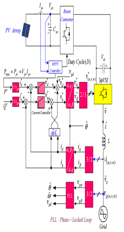
Figure 1 depicts the circuit architecture for the three-phase grid-connected PV inverters. The PV array, boost converter, DC connection, and inverter make up the inverter. The MPPT controls the boost converter. The transfer of control of the grid’s active and reactive functions is powered by a three-phase inverter.
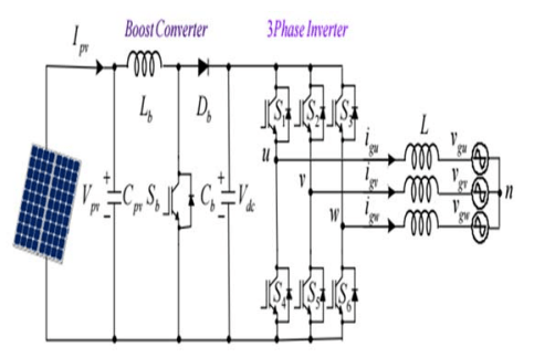
The boost converter and switching frequency of the three-phase inverter are defined for the 380V/50Hz three-phase PV power conditioning system.
2.1 MPPT Algorithm
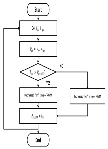
In this section, it will be discussed the perturbation and observation-based MPPT approaches in depth [4]. With the help of these methods, it can determine the current power output of solar panels. An increase in duty cycle may be appropriate in some locations but not others (D). For optimal performance, the converter must be raised or lowered such that it operates near its maximum power point. Figure 2 shows the outcome of a straightforward PV power comparison, or straightforward MPPT, in which Ppv (k) denotes the PV power that is now in use and Ppv (k-1) denotes the previous number.
2.1 MPPT Algorithm In this section, it will be discussed the perturbation and observation-based MPPT approaches in depth [4]. With the help of these methods, it can determine the current power output of solar panels. An increase in duty cycle may be appropriate in some locations but not others (D). For optimal performance, the converter must be raised or lowered such that it operates near its maximum power point. Figure 2 shows the outcome of a straightforward PV power comparison, or straightforward MPPT, in which Ppv (k) denotes the PV power that is now in use and Ppv (k-1) denotes the previous number.

2.2 Power Control: Active and Reactive
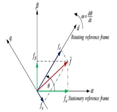
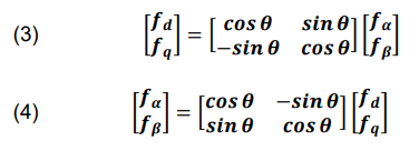
In this subsection, the suggested active and reactive power regulation is introduced. The transformation matrices between the phase and space vectors in Fig. 4 are 3/2 and 2/3 according to (1) and (2), respectively. where f denotes the current or voltage [8].
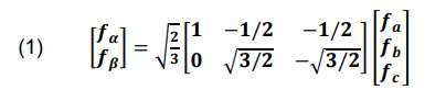
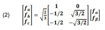
Figure 4 displays the equivalent representations of the rotating and stationary frames, matrices for the axis transformation and its inverse. Where “→” denotes the spatial vector component, d and q denote the rotating reference frame’s components, and α, β denote the fixed reference frame’s components. Grid voltage has an angular frequency of ω (= dθ / dt) [9].
The stationary reference frame’s active power (P) and reactive power (Q) are calculated using (5). When the rotating reference frame and grid voltage are synced, the rotating reference frame’s vq equals zero, and P and Q may then be determined using (6) [10].

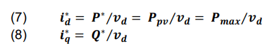
As noted, the d-axis current or active power order (𝑖*d) is recommended to ensure the grid obtains the maximum amount of electricity possible (7). The q-axis current or reactive power order (𝑖*q) is gathered in (6) in order to manage reactive power by regulating the reactive power (8) [11].
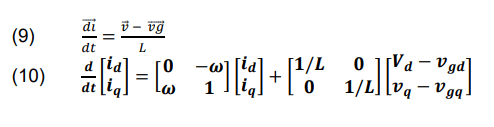
According to (9) and (10), respectively, Figure 4 shows the state equations for both stationary and rotating reference frames. Where “*” signifies the ordered value and “^” indicates the PLL’s approximate amount [12].
The voltage orders are shown in equation (11), which is what equation (10) becomes in a stable state (12). Where v′d and v′q are the current controller voltages on the d- and q-axes, respectively.
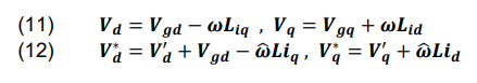
where: 𝑉’d– feedback term, 𝑉gd – ŵLiq– feedforward term, 𝑉’q – feedback term, ŵLid– feedforward term.
2.3 Space vector PLL design
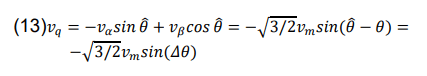
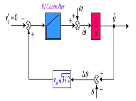
Since PLL management is required by the utility system to synchronize inverter voltage output to the connected utilities, this section provides an overview of the space vector PLL. Grid phase voltages are located and converted into a space vector quantity. when the grid voltage and the rotating frame are synchronized, the vq on the rotating frame equals zero. As a result, the PI controller controls the vq to zero. The space vector PLL block diagram is seen in Fig. 5. The vq’s small-signal is examined to be able to construct the PI controller. When the PLL is in control of vq, a relevance of vq is displayed in (13).
Because the Δθ is quite small near the balance operating conditions, the sin (Δθ) is about Δθ. A space vector PLL’s small-signal circuit diagram is shown in Fig. 6.

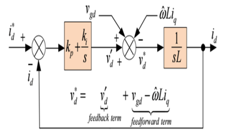
2.4 Current Controller Design This subsection discusses current control as a way to regulate the ordered active and reactive power [13]. Figure 7 depicts the voltage command that drives the d-axis current loop (12). Noting that the PLL control and loop-transfer functions are similar, the PI controller was designed in a similar fashion. The crossover frequency (w0) is determined to be 1000 rad/s in order to demand the risetime (tr) of approximately 2.2 ms using the equation tr ≈ 2.2 / w0 and a corner frequency equal to 25% of the crossover frequency is chosen. Then, the kp and ki are, respectively, 10 and 50000. The identical value uses the q-axis current controller’s PI gain.
The proposed control strategies are shown in Fig. 8.
3. Results of the simulation
In this part, it will be described the simulation procedure used to evaluate the performance of suggested control schemes. The MATLAB R2021b simulation program is used.
Table 1. System design requirements
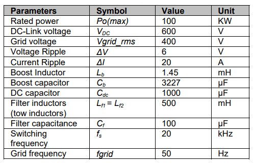
At maximum power (100 KW) and average solar intensity (1000 W/m2), the photovoltaic modules’ voltage and current are 290V and 345.45A, respectively. In Figs. 9 and 10, the simulation values are presented.
Investigate 1: The fundamental waveforms of the proposed PV inverter are displayed in Fig. 9 for a variety of reactive powers and a constant active power. Modifications are made so that there is 1000 W/m2 of solar irradiation (S).
Figure 9 shows the voltage, current, and reactive power (Q) injected or absorbed for the three-phase grid. The Q* has a value of zero at the beginning. At time interval t1, the Q* abruptly increases from 0 to 10 kvar. Therefore, as the reactive power command rises, the igu’s magnitude and phase angle do as well. The Q suddenly takes 10 kvar from the grid at time interval t3. At times t2 and t4, 100 KW of active electricity are sent into the grid by the grid-connected inverter of the PV system, which operates at a unity power factor. It is discovered that the suggested control methods can smoothly manage the reactive output power of the PV inverter without severely reducing active power.
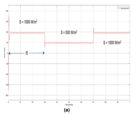
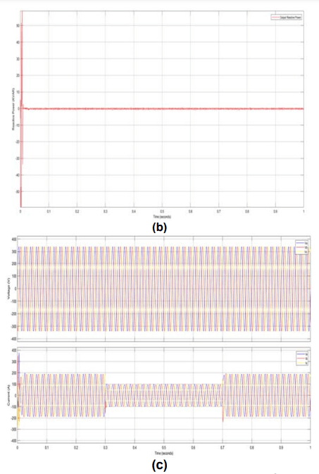
Investigate 2: In Fig. 10, the primary waveforms of the suggested PV inverter are shown when it is operating with a constant reactive power of zero and under varied active power or solar intensity circumstances (S).
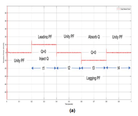
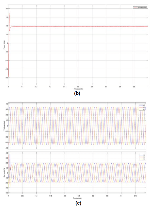
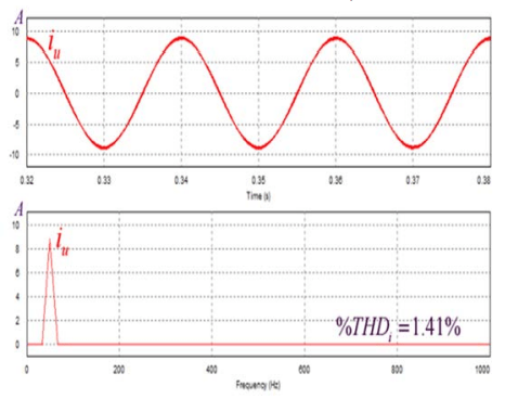
Figure 10 displays the three-phase grid’s voltage, current, and active power output. At time interval t5, the solar irradiance (S) was originally set at 1000 W/m2, or 100 KW of active power command. S rapidly falls from 1000 W/m2 to 500 W/m2. The active power command’s step causes the Ppv and P to rapidly change to 500 KW, as planned, and the amplitude of grid currents to similarly abruptly change, without oscillation. It should be observed that the MPPT operation transitions smoothly and reacts quickly to the peak power point. The harmonic spectra of the u-phase inverter at steady state operation with S = 1000 W/m2 is depicted in Fig. 11. The u-phase inverter has a very low THDi of 1.41 percent.
4. Conclusion
An easier three-phase grid-connected PV inverter with reliable active and reactive power management, minimal current harmonics, seamless transitions, and quick response to MPPT control’s maximum power point was described in this study. Results from simulations were utilized to support this. The simulations also demonstrate the value of PLL and the most recent standards for controller design.
REFERENCES
[1] Afaneen A. Abbood, Mohammed A. Salih and Hassan N. Muslim “Management of Electricity Peak Load for Residential Sector in Baghdad City by Using Solar Generation” International Journal of Energy and Environment, Vol 8, Issue 1, pp.63-72, 2017.
[2] H. J. Avelar, W. A. Parreira, J. B. Vieira, L. C. G. De Freitas, and E. A. A. Coelho, “A state equation model of a single-phase grid-connected inverter using a droop control scheme with extra phase shift control action,” IEEE Trans. Ind. Electron., vol. 59, no. 3, pp. 1527–1537, 2012, doi: 10.1109/TIE.2011.2163372.
[3] A. A. Abbood, M. A. Salih, and A. Y. Mohammed, “INTERNATIONAL JOURNAL OF ENERGY AND ENVIRONMENT Modeling and simulation of 1mw grid connected photovoltaic system in Karbala city,” J. homepage http://www.IJEE.IEEFoundation.org ISSN, vol. 9, no. 2, pp. 2076– 2909, 2018, [Online]. Available: http://www.IJEE.IEEFoundation.org.
[4] A. Cagnano, E. De Tuglie, M. Liserre, and R. A. Mastromauro, “Online optimal reactive power control strategy of PV inverters,” IEEE Trans. Ind. Electron., vol. 58, no. 10, pp. 4549–4558, 2011, doi: 10.1109/TIE.2011.2116757.
[5] T. Kok Soon, S. Mekhilef, and A. Safari, “Simple and low-cost incremental conductance maximum power point tracking using buck-boost converter,” J. Renew. Sustain. Energy, vol. 5, no. 2, 2013, doi: 10.1063/1.4794749.
[6] T. Aung and T. L. Naing, “DC-link voltage control of DC-DC boost converter-inverter system with PI controller,” World Acad. Sci. Eng. Technol. Int. J. Electr. Comput. Eng., vol. 12, no. 11, pp. 848–856, 2018.
[7] R. I. Putri, S. Wibowo, and M. Rifa’i, “Maximum power point tracking for photovoltaic using incremental conductance method,” Energy Procedia, vol. 68, pp. 22–30, 2015, doi: 10.1016/j.egypro.2015.03.228.
[8] F. Blaabjerg, R. Teodorescu, M. Liserre, and A. V. Timbus, “Overview of control and grid synchronization for distributed power generation systems,” IEEE Trans. Ind. Electron., vol. 53, no. 5, pp. 1398–1409, 2006, doi: 10.1109/TIE.2006.881997.
[9] O. Rabiaa, B. H. Mouna, S. Lassaad, F. Aymen, and A. Aicha, “Cascade Control Loop of DC-DC Boost Converter Using PI Controller,” Int. Symp. Adv. Electr. Commun. Technol. ISAECT 2018 – Proc., no. Ccm, pp. 1–5, 2019, doi: 10.1109/ISAECT.2018.8618859.
[10] T. I. Suyata, S. Po-Ngam, and C. Tarasantisuk, “The active power and reactive power control for three-phase gridconnected photovoltaic inverters,” ECTI-CON 2015 – 2015 12th Int. Conf. Electr. Eng. Comput. Telecommun. Inf. Technol., vol.2, no. 1, 2015, doi: 10.1109/ECTICon.2015.7207066.
[11] T. Huang, X. Shi, Y. Sun, and D. Wang, “Three-phase photovoltaic grid-connected inverter based on feedforward decoupling control,” ICMREE 2013 – Proc. 2013 Int. Conf. Mater. Renew. Energy Environ., vol. 2, pp. 476–480, 2013, doi: 10.1109/ICMREE.2013.6893714.
[12] R. Benadli, B. Khiari, and A. Sellami, “Three-phase gridconnected photovoltaic system with maximum power point tracking technique based on voltage-oriented control and using sliding mode controller,” 2015 6th Int. Renew. Energy Congr. IREC 2015, pp. 0–5, 2015, doi: 10.1109/IREC.2015.7110963.
[13] H. A. Hussein, A. J. Mahdi, and T. M. Abdul-Wahhab, “CurrentControl Inverter Schemes for a Grid – Connected PV Generator,” IOP Conf. Ser. Mater. Sci. Eng., vol. 1105, no. 1, p. 012018, 2021, doi: 10.1088/1757-899x/1105/1/012018.
Authors: Adnan Majeed Abed, received the Engineer degree in electrical Engineering from University of Technology, BaghdadIraq, in 2008. He also has a BA in English from the College of Languages, University of Baghdad, Iraq in 2013. He has been working as an electrical engineer in the Iraqi Ministry of Electricity
since 2008 until now. You can connect with me by this e-mail: eee.20.55@grad.uotechnology.edu.iq .
Afaneen Anwer Alkhazraji was born in Baghdad, lraq in January of 1967.she received her B. Sc in 1990 from Baghdad university. Her M. Sc and PhD degrees in 1998 and 2005 respectively from university of technology, Iraq. She is an assistant professor since 2006. Her field of interest is power system operation and control. She had more than 35 published papers. Supervised more than 30 Doctor and master students.
E-mail: 30237@uotechnology.edu.iq
Shatha S. Abdulla received her B.Sc. and M.Sc. degree in Electrical and Electronic Engineering from University of Technology, Baghdad-Iraq, in 2000 and 2003 respectively. She was awarded a PhD degree from University of Cranefield, UK, in 2018. since 2005 she has been a Lecture in Electrical Engineering in the Department of Engineering at University of Technology, where she teaches Electrical Machines, Power System, Engineering Analysis and electric circuits. E-mail 30070@uotechnology.edu.iq
Source & Publisher Item Identifier: PRZEGLĄD ELEKTROTECHNICZNY, ISSN 0033-2097, R. 99 NR 4/2023. doi:10.15199/48.2023.04.29
