Published by 1. Oleksandr KOZLOVSKYI1, 2. Dmitro TRUSHAKOV1, 3. Oleksandr SAVCHENKO2, 4. Serhiy RENDZINYAK3, 5. Vasyl KORUD3, Central Ukrainian National Technical University (1), Kharkiv Petro Vasylenko National Technical University of Agriculture (2), Lviv Polytechnic National University (3)
ORCID: 1.0000-0001-6885-5994; 2.0000-0003-0326-2383, 3.0000-0002-6401-0852, 4.0000-0003-4544-4871, 5.0000-0002-1289-3534
Abstract. Methods of protection of wires of overhead power lines of group “anti-icing” are analyzed. The expediency of applying the winding method of protection of wires of overhead lines in operation for a long time is shown. Based on numerical simulations of the hydrodynamic problem, the degree of influence of the protective coating on the wind load of the wire is analyzed. The research results showed a decrease in the modified wire’s drag coefficient with increasing wind speed.
Streszczenie. Przeanalizowano metody ochrony przewodów linii napowietrznych z grupy „przeciwoblodzeniowa”. Pokazano celowość zastosowania metody uzwojenia do ochrony przewodów linii napowietrznych eksploatowanych od dłuższego czasu. Wykorzystując symulacje numeryczne zagadnienia hydrodynamicznego analizowany jest stopień wpływu powłoki ochronnej na obciążenie żyły kabla wiatrem. Wyniki badań wykazały spadek współczynnika rezystancji zmodyfikowanej żyły wraz ze wzrostem prędkości wiatru. (Poprawa charakterystyk pracy nieizolowanych napowietrznych linii elektroenergetycznych)
Keywords: overhead power line, wind load, drag coefficient, numerical simulation.
Słowa kluczowe: linia napowietrzna, obciążenie wiatrem, współczynnik oporu, symulacja numeryczna.
Introduction
In 2020, the power distribution system of Ukraine included more than 330 000 km of overhead power transmission lines (OHTL) with a voltage of 6-35 kV [1]. The vast majority of these lines were built using all aluminium conductors (AAC) and aluminium conductor steel reinforced (ACSR) grades A and AC (European analogs, respectively, A and A/S [2]). These wires are a rope-like structure obtained by twisting individual cylindrical wires around the central one. Experience of operation of such OHTLs has shown their reduced reliability to extreme environmental influences, particularly wind and ice-wind loads. That is primarily due to the design features of the wire, due to which it has a greater drag coefficient under certain conditions than the cylinder of equivalent diameter, and its shape contributes to the accumulation of ice-frost deposits, which leads to increased mechanical loads on the OHTL.
In the 1980s, to eliminate the drawbacks of AAC and ACSR wires, the development of protected wires type SAX has begun in Finland. Today, the SAX system includes wires insulated with cross-linked polyethylene, the necessary linear armature, lightning protection, and vibration protection devices. Implementing the SAX system allowed to increase the reliability of overhead lines by reducing the adhesion of ice-frost deposits to the polymer insulation of the wire, reducing the drag coefficient, and eliminating the possibility of interphase shortcut circuits due to touching of wires and tree branches.
Today, Ukrainian manufacturers also manufacture shielded wires of type SIP-3 for 6-35 kV overhead lines, but they have not yet become widespread in the power grid. This situation appears because of high initial capital costs for the construction of new OHTLs; for example, only the most protected wires have about 1.5 times higher cost than wires of types AAC, ACSR. At the same time, a significant part of the overhead lines of 6-35 kV distribution networks have exhausted their normal service life but are in operation due to a lack of resources for their reconstruction and replacement. Therefore, there is a need to develop specific ways to improve the design of transmission line wires of distribution networks in operation.
Review of publications
All known methods of protection of OHTL wires from ice loads are divided into two large groups: “de-icing” (DI) and “anti-icing” (AI) [3].
The methods of the DI group consist in the OHTL wire release from ice-frost deposits when the values of mechanical loads on their linear elements close to the critical ones are reached. Typically, these goals bases on using the melting process of ice by artificial short-circuit currents. However, this method has not been widely used in the distribution networks of electricity companies. First of all, this happens because of the electrical equipment operation at melting ice process in modes close to the faulty ones. It can occur in some cases of forced technological breaks or interruptions in electricity supply to consumers, with the need to attract additional investment, for example, specialized equipment needed to adapt the power system with the OHTL [4, 5], as well as in the absence of a guarantee in the success of a particular smelting. In general, the power system consists of both components with lumped parameters and components with distributed parameters. Modelling the state of such a system requires the development of complex algorithms, for example, based on diakoptic approaches, and the use of modern software [6]. Thus, the methods of DI group are of little use for distribution networks that have a significant service life.
The methods of AI group AI are designed to wholly or partially prevent the formation of ice-frost deposits on the wire of the OHTL by creating a protective coating on it. Among these methods, the most common is a subgroup of so-called passive methods, i.e. those based on creating protective coatings that do not require an external source of energy for their work. The technology of applying a protective coating on the wire can be classified as follows: plasma spraying, extrusion, dyeing (lubricating), and winding [7-11].
Plasma spraying methods [7] and extrusion can be implemented only in production conditions and dyeing and winding [8-11] in the field conditions.
The painting method consists of applying unique chemical compounds to the wire through pneumatic spraying, lubrication, immersion, etc. The protective coatings created in this way can reduce the adhesion of water and ice droplets to the wire, and enter into an exothermic reaction with water droplets with intense heat release.
The main reasons that have interfered with the widespread implementation of these technologies in electric distribution networks are:
– a limited number of working cycles of “freezing-melting” of chemical compounds, and hence the need to reapply them before the start of the ice season;
– high-quality application of some protective coatings requires multi-stage preparation of the wire surface, which is difficult to implement in the field;
– the effectiveness of many protective coatings is reduced due to their interaction with natural or technogenic pollutants.
By shell methods, a rigid protective shell on the transmission line conductors is created, which has hydro-icephobic properties or promotes self-cleaning of the wire from ice-frost deposits during wet growth. A variant of the shell method is winding, consisting of a spiral winding on the surface of the tape wire, which performs a protective function [8-11].
The main advantage of the winding method is the possibility of its implementation on overhead transmission lines during operation. Technical implementation of this method can achieve lower costs by using robots based on Line-Scout technology [12].
Creating a protective shell on the surface of the wire will change its aerodynamic drag and hence change the wind load on the overhead transmission line in general. Many theoretical, laboratory and field studies were conducted to assess the influence of roughness on the drag coefficient of the OHTL wire form. As a result, new types of wires with reduced aerodynamic drag were developed [13-15]. However, they are designed for high and ultra-high voltage overhead transmission lines. Therefore, the problem of estimating the change in the load on the modified OHTL wire of the distribution power networks from wind is actual till now.
Basic researching principles
To more effectively solve the stated goal, the problem of determining the influence in wind load on the modified wire was divided into two more straightforward tasks:
1) determination of the drag coefficient CD of the modified wire;
2) assessment of the change in load P from wind pressure on the modified wire.
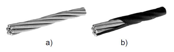
Wires of grades A (AC) are a rope-like structure consisting of one or more layers of wires spirally wound around the central core. The adjacent wires inside one winding touch each other at two diametrically opposite points. It is a peculiarity of the wires of these types. As a result, the outer contour of the wire consists of the sum of the upper arcs of the upper winding wires (Fig. 1, a). Therefore, the transmission line wire has a complex geometric shape, so the study of CD changes should be carried out by computer simulation.
Statement of the first problem
Homogeneous air flow with a constant velocity v is fed perpendicular to the longitudinal axis of the sample. The flow rate of the test samples is such that the Mach number is M << 1. It is necessary to determine the drag coefficient of the shape of each test sample (Fig. 1) when changing the airflow rate in the range from 6 m/s to 35 m/s; to equate the calculated values of the component of the coefficient of aerodynamic drag along the axis x for a circular cylinder with the data of physical experiments.
The hydrodynamic problem was solved by numerical simulation in the Fluent software module of the ANSYS software package. The motion of the fluid is described by the Reynolds-Averaged Navier-Stokes (RANS) equations [16].
The following assumptions were made during the simulation:
– air is an incompressible, viscous liquid;
– fluid regime is turbulent;
– point contact between the ends of the arcs of the envelope curve of the wire AC-50/8 is replaced by arcs of fixed size;
– the shell of the modified wire is solid and has a thickness of 0.5 mm;
– the circular cylinder’s diameter is equal to the diameter of the wire AC-50/8: dc = dw = 9.6 mm;
– the effect of the sample length on the CD is neglected;
– the flow is directed perpendicular to the wire and the arc segment of the modified wire (Fig. 2, b, c).
The solution to this problem is performed in a two-dimensional flat formulation, so appropriate profiles were pre-built for each prototype.
The wire profile is based on a section of steel aluminum wire AC-50/8 (Fig. 2), which has been in operation for more than 15 years. A section usage made it possible to determine the actual height of the arcs of the wire leading round. Due to the deformation of the wires during the retraction of the wire under operation conditions, their contact points were shifted from the center of the wire by an average length of 0.26 mm.

The modified wire profile is obtained by connecting the vertices of the rounding arcs with segments, followed by the displacement of the resulting hexagon with smoothed angles at a distance of 0.5 mm from its center.
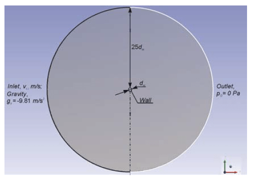
The computational domain of the model was developed considering the experience of conducting similar numerical
experiments [15, 17, 18] and is presented in Fig. 3. The distance from the test sample to the sidewalls of the domain was assumed to be equal to 25dw. The area occupied by the test sample was excluded from the calculation.
In numerical modeling, the accuracy of calculating the drag coefficient CD of the shape of the sample is determined by the correctness of the choice of turbulence model and construction quality of the calculation grid.
In solving the problem, the Spalart-Allmaras model (SA) was chosen to consider fluid turbulence [16].
The Spalart-Allmaras model is a relatively simple one-parameter model that describes the entire flow region, including the boundary regions. It gives good results for moderately complex flows in the boundary layer under a pressure gradient in external aerodynamics problems. Its features are fairly good stability, reliability, and relatively low requirements for computing resources.
The chosen turbulence model is sensitive to the details of the calculation grid, especially in the boundary layer area. Therefore, the thickness of the first layer of elements (cells) of the grid significantly impacts the accuracy of calculations. To save computing resources, curved structured (regular) grids were used. Their quality was controlled by the dimensionless parameter of the near-wall layer y+, which was in the range of y+ ≤ 1.0, according to the recommendations presented in [16]. Thus, grid sets were created for the profile of each prototype. The obtained sets of grids were also checked for regularity by increasing their frequency until the grid convergence of the mathematical problem solution was achieved.
Solvers of the second order of accuracy were chosen to solve the model equations.
The following initial and boundary conditions were set during the simulation:
– pressure and speed communication scheme: coupled;
– the test sample is stationary during the flow;
– flow temperature (air), ta = 273.16°K;
– flow density, ρt=0 = 1.293 kg/m3;
– input condition: inlet (velocity), vx = {6, 10, 15, 20, 25, 30, 35} m/s;
– output condition: pressure outlet, pG = 0 Pa;
– condition on the surface of the sample: wall.
The drag coefficient of the shape of the samples is calculated by the well-known expression:

where: F is the total force acting in the direction of flow on the test sample, N; ρ is air density, kg/m3; v is air velocity, m/s; S is the characteristic area of the sample perpendicular to the airflow, m2; φ is the angle between the direction of wind flow and the surface of the wire, under the condition of the task φ = 90°, so sin φ = 1.
The numerical experiment was performed for sections: the circular cylinder with a diameter of 9.6 mm; the wire was of AC-50/8 type; modifications of the wire AC-50/8* with a wall thickness of the protective coating equal to 0.5 mm.
The mathematical model setup was performed by determining the aerodynamic characteristics of the circular cylinder and comparing the obtained results with the data defined from physical experiments, the results of which are given in [19, 20].
All prototypes: the cylinder, the overhead line wire, the hexagon with rounded faces (modernized wire) are inconveniently streamlined bodies, forming a large separation area with back-circulating flows due to a significant increase of pressure (Fig. 4, Fig. 5) [21]. The Reynolds number (Re) for all samples under selected conditions is in the range of 4.3ꞏ103-4.0ꞏ104.
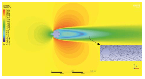
The wrapping structure of the AC-50/8 wire in the cross-section was obtained based on the developed numerical model is presented in Fig. 4. On its front part, the zone of stagnation with zero speed is formed. On the bow, the pressure distribution corresponds to the theoretical pressure distribution when flowing through the flow of a non-viscous liquid. On the reverse side, there is a large area of separation with reverse circulation. In the depressions between the wires of the wire are formed reverse flows of low speed. The change in flow structure leads to a significant decrease in pressure. The main flow separation is observed in the upper part of the wire. At breakpoints in the depressions, reverse currents of low velocity not more than 1 m/s are formed.
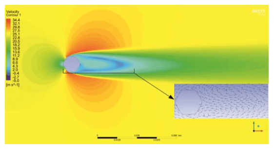
In Fig. 5 the distribution of speed in the cross-section of the wire AC-50/8* is given. Compared to the AC-50/8 wire, which has six wires in the upper twist, the modified wire has no small circulation zones between the individual wires. Although it also has discrete vortices that distort mainstream flow lines. They have slightly less power. Two stagnant zones are formed on the sides of the modified wire (bottom and top), leading to flow separation.

The change in the drag coefficients of the mold for all test specimens depending on the flow velocity is presented in Fig. 6. For the cylinder, this parameter is nonlinear and tends to local growing. Absolute error between the calculated value of the drag coefficient of a smooth cylinder shape according to the developed model and the experimental data presented in [13] varies between 3-8%.
The peculiarity of the wire of the OHTL of the conventional design is that its phenomenon of the drag crisis corresponds to smaller values of the Reynolds number than for a smooth cylinder of equivalent diameter. In this case, the obtained calculated data differ significantly from the experimental ones, so there is no decline in the obtained dependence of the CD = f(v) in the speed range 11-15 m/s (Fig. 6). The calculated values of the drag coefficient for the AC-50/8 wire at the Reynolds number above the transition number are in the range of 0.97-0.985 (Fig. 6), which are close to the results of experimental studies presented in [13] (CD = 0.98-1.0) and to the generally accepted normative value of 1.2 for maximum wind loads [22]. The drag curve of the shape of the modified wire changes linearly and is descending.
Statement of the second problem
Standard and modified wires of the overhead transmission line of failure class of 2KB type [22] of the distribution network are under load because of the wind pressure. It is necessary to determine the change in wind load when replacing the standard wire with a modified one in the range of wind speeds from 6 m/s to 27 m/s.
In the general case, the wind load on the wire can be determined from (1):

Then the change in wind load on the wire will be

or in expanded form

where indices 1, 2 are concerning, respectively, to the parameters of standard and modified wire; ΔS is the increase in the characteristic area of the wire due to the creation of a protective sheath of the wire ΔS = S2 – S1.
It follows from (2) that the reduction of the wind load on the wire can be achieved by reducing the roughness of its surface (CD1 > CD2) and the use of the minimum allowable wall thickness of the protective coating (ΔS → min).
The dependence of the change in load on the wire from the airflow flow calculated using the formula (2) is presented in Fig. 7.

Discussion
Analysis of the obtained data of the numerical experiment (Fig. 7) shows that the creation of a protective coating on the wire AC-50/8 changes the wind load on it in the range from –7.0% to +2.5%, so at wind speeds from 15 up to 25 m/s it decreases, and at higher speed begins to increase. This negative load change can be offset by optimizing the protective coating profile. It is expected that with increasing wire diameter to be modified, the effect from a decrease of CD will increase and can be increased to 30% after the point of drag crisis (wind speed range 25-40 m/s) [13].
Further research aims to determine the critical wall thickness of the protective coating (critical diameter of the modified wire), that is, the value of the thickness of the protective sheath of the wire, to which the wind load on its does not increase.
Conclusions
1. The expediency of using the winding method in creating passive protective coatings on uninsulated wires of the OHTL, which are in operation based on LineScout technology, is substantiated.
2. It is established that due to the change of the aerodynamic profile of the standard wire AC-50/8 after its modification, the coefficient of resistance of the form decreases with increasing wind speed.
3. It is established that the creation of a protective coating on the wire AC-50/8 using the winding method at low wind speeds (up to ≈25 m/s) is decreased the wind load on it to 7.0%. At high wind speeds (25-35 m/s), on the contrary, it is increasing to 2.5%. So, this method is sufficiently effective for overhead lines in operation.
REFERENCES
[1] Performance report of Energy and Utilities the National Regulatory Commission in 2019 the year (2020, May 27). Retrieved from https://www.nerc.gov.ua/data/filearch/Catalog3/Richnyi_zvit_N KREKP_2019.pdf
[2] IEC 61089, “Round wire concentric lay overhead electrical stranded conductors,” Published 1991, 65 p.
[3] Farzaneh, M., Atmospheric Icing of Power Networks, Springer Netherlands, 2014, 381 p.
[4] O l e k s a n d r А . S a v c h e n k o , О l e k s a n d r О . M i r o s h n y k , S t a n i s l a v V . D y u b k o , T a r a s S h c h u r , P a w e ł K o m a d a , K a n a t M u s s a b e k o v , Justification of ice melting capacity on 6-10 kV OPL distributing power networks based on fuzzy modeling, Przegląd Elektrotechniczny, 95 (2019), nr 5, 106-109, doi: 10.15199/48.2019.05.26
[5] K o z l o v s k y i , O . , T r u s h a k o v , D . , R e n d z i n y a k , S . , Temperature influence of load current of overhead electrical distribution networks in difficult weather conditions, Acta Technica CSAV (Ceskoslovensk Akademie Ved), 63(2018), No. 5, 701-708
[6] S t a k h i v , P . , R e n d z i n y a k , S . , H o h o l y u k , O . , Modeling of electric power systems based on diakoptic approach and parallel algorithms in modern computer tools, Przegląd Elektrotechniczny, 86 (2010), nr 1, 115-117
[7] Pat. 3276280 Japan, ICI5 H01 B 7/28, H 01 B 7/34. Snow and ice sticking reducing / light and heat shielding type coated power transmission line / Toyoda Minoru, Tomizawa Nobuo, Matsumoto Kiyoshi and et.; applicants and owners KANSAI Electric Power Co; Soko Seiren KK; Mitsubishi Heavy IND Ltd. No JP19910276280; fil. 30.10.1991; pub. 16.4.1993.
[8] H i g u c h i N . , Snow Accumulation Prevention Methods, Hokkaido Electric Power, 1972.
[9] V . N . S e d u n o v , A . V . N a c h a l o v , N . G . T s a r a n o v , e t c . , Proposals for the use of fluoroplastic surface coatings to reduce the mass of ice-frost deposits on wires and lightning protection cables, Electro, 2005, No. 5, 46-48 (in Russian)
[10] Pat. 138930 Ukraine, H02G 7/16 (2006.01). Method of forming anti-icing coating on uninsulated wires and lightning protection cables of overhead power transmission line / O. A. Kozlovskyi; applicants and owners Central Ukrainian National Technical University; fil. 03.06.2019; pub. 10.12.2019 (in Ukrainian)
[11] K o z l o v s k y i , O , T e l i u t a R . , Improvement of design of the Non-insulated wires of the operating overhead power lines, Visnyk Kharkivsʹkoho natsionalʹnoho tekhnichnoho universytetu silʹsʹkoho hospodarstva imeni Petra Vasylenka, 2019, issue 201, 21-22
[12] N . P o u l i o t , P . R i c h a r d a n d S . M o n t a m b a u l t , LineScout Technology Opens the Way to Robotic Inspection and Maintenance of High-Voltage Power Lines, IEEE Power and Energy Technology Systems Journal, March 2015, Vol. 2, No. 1, pp. 1-11, doi: 10.1109/JPETS.2015.2395388
[13] N a o s h i K i k u c h i , Y u t a k a M a t s u z a k i , H i d e o B a n s e , T a k a o K a n e k o , A k i h i r o Y u k i n o a n d H i r o t a k a I s h i d a , Development of Conductors with Reduced Wind Drag and Wind Noise for Overhead Power Transmission Lines, Furukawa Review, 2002, No. 21, 50-55
[14] D o n g Q i n g L i , Z h e n L i , Z h e n L i u , L o n g L i u , C h a n g L o n g Y a n g , We i F a n , L u Y u Y a n g a n d J i a J u n S i , Application Research on Drag Reduced Conductors for Electric Power Transmission Lines in Strong Wind Areas, Proc. of 2016 International Conference on Electronic, Information and Computer Engineering, ICEICE 2016, 26-27 April 2016, Vol. 448, March 2016, Article number 01093, doi: 10.1051/matecconf/20164401093
[15] C h a o M . , J u n Z . , M i n g n i a n W . , Y a o j u n M . , Large Eddy Simulation of Flow over a New Type of Low-Wind- Pressure Conductor Using WALE Model, Proc. of 2019 16th International Bhurban Conference on Applied Sciences and Technology, IBCAST 2019, 8-12 January 2019, 13 March 2019, pp. 811-815, Article number 8667236, doi: 10.1109/IBCAST.2019.8667236
[16] ANSYS Fluent User’s Guide R.19.2, ANSYS Inc., Canonsburg, PA, August 2018.
[17] R a v i n d r a n , M a g e s h R . , Computational Study for Analysis of the Potential for Drag Reduction for Flow around a Circular Cylinder and Cactus-Shaped Cylinders, Journal of Mechanical and Civil Engineering, 2015, 13-24
[18] H y u n A . S o n , S u n g s u L e e a n d J o o y o n g L e e , Numerical Analysis of Drag Force Acting on 2D Cylinder Immersed in Accelerated Flow, Water, Vol. 12, No. 6, 2020, A.N. 1970, doi: 10.3390/w12061790
[19] M i l t o n v a n D y k e , An Album of Fluid Motion, Moscow, Mir, 1986,184 p. (in Russian)
[20] R o n a l d L . P a n t o n , Incompressible flow, 4th Edition, Wiley, 2013, 912 p.
[21] C . D e m a r t i n o , F . R i c c i a r d e l l i , Aerodynamics of nominally circular cylinders: A review of experimental results for Civil Engineering applications, Engineering Structures, 137 (2017), 76-114, doi: 10.1016/j.engstruct.2017.01.023
[22] Regulations of arrangement of electrical installations, Kharkiv, Fort, 2017, 760 p. (in Ukrainian)
Authors: assoc. prof. Oleksandr Kozlovskyi, Central Ukrainian National Technical University, pr. Universytetskyi 8, 25006 Kropyvnytskyi, Ukraine, E-mail: kozlovskyioa@gmail.com; Assoc. prof. Dmitro Trushakov, Central Ukrainian National Technical University, pr. Universytetskyi 8, 25006 Kropyvnytskyi, Ukraine, Email: dmitro.trushakov@gmail.com; assoc. prof. Oleksandr Savchenko, Kharkiv Petro Vasylenko National Technical University of Agriculture, ul. Alchevskih 44, 61002 Kharkiv, Ukraine, E-mail: savoa@khntusg.info; D.Sc., prof. Serhiy Rendzinyak, Lviv Polytechnic National University, ul. Bandery 12, 79013 Lviv, Ukraine, E-mail: serhii.y.rendziniak@lpnu.ua; assoc. prof. Vasyl Korud, Lviv Polytechnic National University, ul. Bandery 12, 79013 Lviv, Ukraine, E-mail: vasyl.i.korud@lpnu.ua.
Source & Publisher Item Identifier: PRZEGLĄD ELEKTROTECHNICZNY, ISSN 0033-2097, R. 98 NR 2/2022. doi:10.15199/48.2022.02.06
