Published by KARRI HEMANTH KUMAR1, GADI VENKATA SIVA KRISHNA RAO2, Department of Electrical Engineering, Andhra university college of Engineering (A), Andhra university, Vishakhapatnam, India. ORCID: 1. 0000-0001-6198-999X. ORCID: 2. 0000-0003-4314-4816
Abstract: The electrical energy from the sun can be extracted using solar photovoltaic (PV) modules. This energy can be maximized if the connected load resistance matches that of the PV panel. In search of the optimum matching between the PV and the load resistance, the maximum power point tracking (MPPT) technique offers considerable potential. This paper aims to show how the modelling process of an efficient PV system with a DC load can be achieved using an artificial neural network (ANN) controller. This is applied via an innovative methodology, which senses the irradiance and temperature of the PV panel and produces an optimal value of duty ration for the boost converter to obtain the MPPT. The coefficients of this controller have been refined based upon previous data sets using the irradiance and temperature. A gradient descent algorithm is employed to improve the parameters of the ANN controller to achieve an optimal response. The validity of the PV system using the MPPT technique based on the ANN controller is further demonstrated via a series of experimental tests at different ambient conditions. The simulation results show how the MPPT technique based on the ANN controller is more effective in maintaining the optimal power values compared with conventional techniques.
Streszczenie. Energia elektryczna ze słońca może być pozyskiwana za pomocą modułów fotowoltaicznych (PV). Energię tę można zmaksymalizować, jeśli rezystancja podłączonego obciążenia jest zgodna z rezystancją panelu fotowoltaicznego. W poszukiwaniu optymalnego dopasowania między PV a rezystancją obciążenia, technika śledzenia punktu maksymalnej mocy (MPPT) oferuje znaczny potencjał. Niniejszy artykuł ma na celu pokazanie, w jaki sposób można osiągnąć proces modelowania wydajnego systemu fotowoltaicznego z obciążeniem DC przy użyciu kontrolera sztucznej sieci neuronowej (ANN). Jest to stosowane za pomocą innowacyjnej metodologii, która wykrywa natężenie promieniowania i temperaturę panelu fotowoltaicznego i wytwarza optymalną wartość współczynnika wypełnienia dla konwertera doładowania w celu uzyskania MPPT. Współczynniki tego kontrolera zostały udoskonalone w oparciu o poprzednie zestawy danych z wykorzystaniem natężenia promieniowania i temperatury. Algorytm opadania gradientu jest wykorzystywany do poprawy parametrów kontrolera ANN w celu uzyskania optymalnej odpowiedzi. Ważność systemu fotowoltaicznego wykorzystującego technikę MPPT opartą na sterowniku ANN jest dalej demonstrowana w serii testów eksperymentalnych w różnych warunkach otoczenia. Wyniki symulacji pokazują, w jaki sposób technika MPPT oparta na sterowniku ANN skuteczniej utrzymuje optymalne wartości mocy w porównaniu z technikami konwencjonalnymi. (Śledzenie maksymalnego punktu mocy systemu fotowoltaicznego za pomocą sztucznej sieci neuronowej)
Key words: Photovoltaic System, Maximum Power Point Tracking, Artificial Neural Network.
Słowa kluczowe: Saystem fotowoltaiczny, śledzenie maksymalnej mocy, sieć neuronowa
Introduction
Increasing the energy demand around the world has focused attention on the need to develop renewable sustainable sources with minimal environmental impact. Of all the potential renewable sources of energy, that derived from solar power continues to grow in prominence as it can be utilized to generate electrical power without pollution and is readily available around the globe. Most significantly, although the cost of installation is still prohibitive [1,2], once operational, the cost of the operation and maintenance is relatively low and commercially competitive with other available power sources. A key aspect of the solar cell is that it is a not-fixed voltage or current source, and thus depends upon the variation in irradiation, temperature, and load. Therefore, the overall efficiency of the solar array can be considerably low due to these variations. In order to ameliorate the efficiency of the solar cells, the maximum power point tracking (MPPT) technique is utilized to enhance the output. This technique is able to obtain the maximum possible power from a varying source by using a controlled DC-DC converter with a unique tracking algorithm introduced between the photovoltaic (PV) array the load [2].
Many MPPT techniques have been presented in the literature [1, 3, 4] including: Incremental Conductance (IC), Perturb and Observe (P and O), and the Feedback Linearization Method. However, most of them have limitations due to the non-linear characteristics of PV cells. More recently, intelligent techniques employing neural network and fuzzy logic are presented as an effective approach to trace the maximum power from the PV cells commensurate with changing atmospheric conditions [5–8]. Such intelligent techniques based on MPPT provide the facility to achieve a faster response with greater accuracy compared with conventional techniques. In this paper, a fuzzy neural network (FNN) controller based on the MPPT technique has been designed and implemented to control the duty cycle of a boost converter and to elicit the maximum power from the PV cells. The integrating of fuzzy logic with a neural network is more convenient for MPPT compared with conventional controllers by overcoming the limitations of the individual techniques. In particular, this offers higher accuracy with the non-linear behaviour of PV cells. The parameters of the FNN controller are also refined using a gradient descent-based back-propagation algorithm to obtain the optimal results.

PV cell
A PV cell mutates solar energy into DC electrical power via a physical operation known as the photoelectric elect. A PV array is composed of a number of PV cells connected in series and parallel to increment the voltage and current in the array. There are several variations of PV cell models [5,7,9] available to potential users. The classifications of these models depend on many factors, like the irradiation, temperature, elect of shadow, and the cell deviation from the diode operation [8,10]. In this paper, an approach has been adopted to use a single-diode model to represent the PV cell. This can then be modelled by a current source in anti-parallel circuit with a diode. In addition, parallel and series resistances are also included due to leakage current and resistances, as depicted in
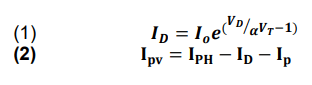
where, 𝐈𝐃 is Diode Current; 𝐈𝐏𝐇 is Photon Current; 𝐈𝐩 is Current through Resistance 𝑹𝑺𝒉 ; 𝐈𝐩𝐯 is Photo Voltaic Current; 𝑹𝑺𝒉 is Shunt resistance; 𝑹𝑺 is Series resistance; 𝐈𝐩𝐯 is Photo Voltaic Voltage; 𝑰𝒐 Diode Saturation Current; 𝑽𝑫 is Diode Voltage; 𝜶 is Boltzmen’s Constant; 𝑽𝑻 is Terminal Voltage
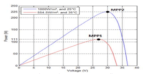
Below mentioned diagrams Fig (2), Fig (3) shows the P-V curve and I-V curve of PV cell respectively.


Boost converter
The core of the MPPT strategy is a DC-DC converter. A DC-DC converter is utilized to transfer the maximum power of solar array to the load side, ensuring that maximum power has been transferred. In this work, the boost converter is utilized to vary the output voltage by adjusting the duty cycle to elicit the maximum power from the solar array, as depicted in Fig.4. The duty cycle of the boost converter is controlled by using the MPPT algorithm. This converter can be designed and modelled to operate at current-continuous mode (CCM) using the following equations.

MPPT technique
The MPPT technique is utilized to obtain the maximum power and efficiency from the solar panel. This consists of a DC-DC converter that interconnects between the PV panel and the load and controller. The photovoltaic modules are not fixed electrical sources and the I–V characteristics are non-linear. This makes it more difficult for utilizing to provide the energy to any load. This is achieved by utilizing a boost converter which can be controlled by varying the duty cycle through an MPPT algorithm [1, 4, 9]. The MPPT controller changes the resistance, as seen from the PV panel, changing the duty cycle of the boost converter, and hence compels the PV panel to extract MPP to the load. In recent years, several techniques have been developed which can effectively track the MPPT.
Fuzzy Neural Network (FNN)
Controller The combination between fuzzy logic and the neural network over the advantages of both networks (human-like IF-THEN rules thinking, ease of incorporating expert knowledge, learning abilities, optimization abilities, and connectionist structures). For the present work, the fuzzy neural network controller is utilized to overcome the drawbacks of the individual techniques and control the PV output power to extract MPP. The FNN can thus be considered as a hybrid form of the neural network, with similarities to the general structure, but having special connections and node operations within the network. The FNN controller consists of a four-layer neural network based on fuzzy logic with an optimization algorithm for learning the neural network. The basic function of each layer is described.
Simulation results MPPT PV control system with artificial neural network
ANN technique is used with MPPT to optimize the response of the MPPT, in order to increase the efficiency of PV module. The structure of the system which is utilized in this paper is presented in Fig.5.

Modelling booster converter
The output DC voltage of the boost converter is greater than the input DC voltage. Consequently, from the equations were shown in previous sections, a DC-DC boost converter model is designed and applied using MATLAB/SIMULINK.
The design specifications of boost converter are shown in table 1. The specifications are for a variable value of the input voltage of the boost converter where the input voltage comes from the renewable source and the output voltage of boost converter is fixed to 45V DC.
Table 1. Specification of Boost Controller.

PV control system using ANN
The output characteristics of the two cases of PV module are nonlinear; moreover, the solar irradiance is changed continuously and unpredictable, so the maximum power point varied continuously, as seen in Fig.6.
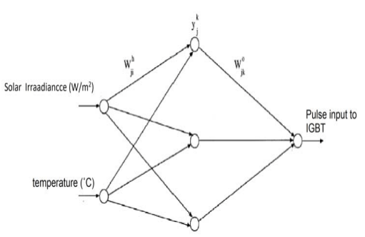
In this paper, it can implement an ANN technique for tracking the maximum output power of the PV modules by commanding the boost converter. The architecture of ANN was shown in Fig.7. It is having Solar Irradiance, Temperature as input and Pulse input to IGBT as output. To design an ANN model, firstly according to the “nnstart” or “nntool” functions is used to create the ANN model. The proposed ANN in this paper is a multilayer feed forward back propagation NN, which consist of two layers which are hidden layer and output layer. Inputs on this design are irradiance and temperature also the output of the ANN model is a voltage at maximum power. Neurons number in each layer and structure of multilayer feed forward propagation NN are mostly variable and thus determined by experience and trial and error. So many of the trials are implemented until reaching the best design. And the final design consists of hidden layer constructed of 5 neurons whose activation function is a tangent sigmoid and the output layer has 1 neuron which activation function is a pure linear transfer function. The “trainlm” tool at MATLAB is used to train the ANN using Levenberg-Marquardt, so the ANN is trained to discover the relationship between inputs (irradiation and temperature) and the output (maximum voltage) as shown in Fig.8.

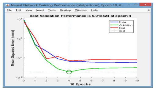
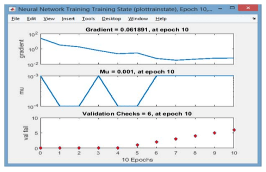
Three kinds of samples are implemented on the ANN model training samples, validation samples for measuring NN generalization and testing samples for measuring the performance of the NN. Where the samples almost divide into 70 % training, 15 % validation and 15 % testing. Mean Squared Error is the average squared variance between outputs and targets set. Lower values are generally better. Regression R Values measured the correlation between outputs and targets. MSE with different epochs, training state plot and the R plot are presented in the next Fig.9. and fig.10. respectively.
Directly connected PV with load
In this section the PV directly connected with load without using any controller techniques. MPPT technique does not employ. The model was tested with nominal operating conditions (25oC and 1KW/m2 ), Fig.11. shows output power with no controller.


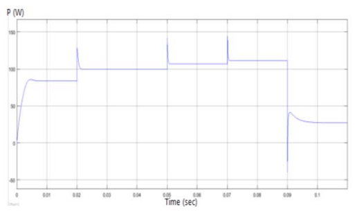
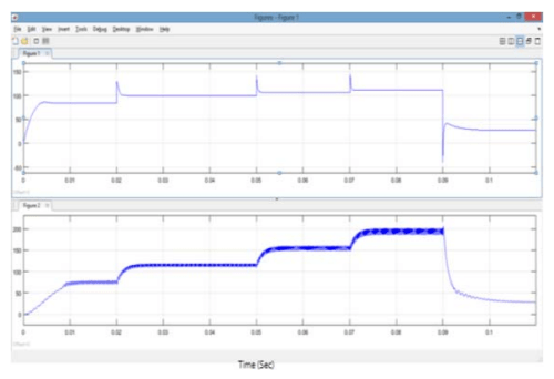
To test the designed ANN MPPT technique and compare its performance against the direct method, they were implemented in MATLAB/SIMULINK with a resistive load. The simulation was performed under rapidly varying and sudden change in solar irradiation levels starting at 400W/m2, then increased to 600W/m2 then further increased to 800 W/m2 then became 1000W/m2 thereafter drop to 200W/m2 as shown in Fig.11. The Fig.12, 13, 14 and 15 show the results of the PV module with no controller which show the output power for variable radiation and constant temperature, variable temperature and constant irradiance and variable irradiation and variable temperature respectively.

In fig.15. due to sudden change in irradiance the negative power was established, but it vanishes and came back to original positive power in fraction of seconds.
The PV system with ANN MPPT controller
This yields an indication that, the DCS is working far from the maximum power point all the time. Thus, when the radiation varies the ANN model controller calibrates the duty cycle, to get the operating points where the power is at the maximum value (MPP), and that happened by decreasing the PV current operating point and increase the PV voltage operating.
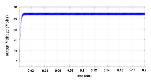
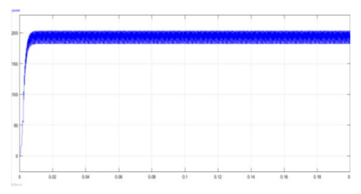
CASE A: Output voltage and output power at (1 kW/m2) and (25˚C) are illustrated in Fig.16. and Fig.17.
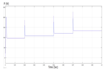
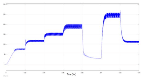
CASE B: Output power is shown for variable irradiation 400W/m2, 600W/m2, 800W/m2, 1kW/m2, and 200W/m2 and constant temperature 25˚C at Fig.18.

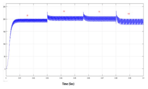
CASE C: Output power is shown for constant irradiation (1KW/m2) and different temperatures 25˚, 50˚, 75˚and 100˚ C in Fig.19.
CASE D: Output power is shown for variable irradiation and variable temperature at Fig.20.


At the direct connected system without ANN MPPT controller is working with more disturbances, in ANN MPPT the disturbances are less compared direct connected MPPT. This can be clearly observed in fig.23.
In addition, the ANN MPPT technology shows the ability to adapt rapidly to the rapid change in radiation and to avert the accompanying deviation from the maximum power point. Finally, we can say in general that the ANN controller, which is applied to MPPT technique is effective to track the maximum power point and this technique can increase the efficiency of the PV module when rapid change in radiation and temperature occur.
Conclusion
Recently, solar energy has become increasingly and effectively used worldwide because of the increasing demand for energy Because of the relatively high cost of the solar system, the overall efficiency of the solar cell system should be increased to reduce the use of a large amount of solar panels; so MPPT technology has been used to improve the efficiency of the solar cell system. An artificial intelligent maximum power point tracking technique using neural networks is proposed, which predicts the appropriate duty cycle for which the DC-DC converter can operate with and thus maximum power can be obtained from the PV system. The system comprises of PV module, DC-DC boost converter and ANN controller to get MPPT. Each component is simulated and discussed in details using MATLAB/SIMULINK software. The PV model was verified and it gave almost typical results like the ones supplied by the manufacturer data sheet. The ANN MPPT method is designed and developed and it is compared with the direct method without MPPT system. Also, DC-DC boost converter model is simulated which is the key for changing the PV’s terminal voltage to track the maximum power. The system is tested with the artificial neural network MPPT method under sudden irradiance and variable temperature, and the ANN method gave very fast and accurate response. Where an ANN MPPT controller has been designed and implemented; the designed system increased the overall efficiency of the solar system by more than 14%.
REFERENCES
1. A. Costa, De Souza, F. Cardoso Melo, T. Lima Oliveira and C. Eduardo Tavares, “Performance Analysis of the Computational Implementation of a Simplified PV Model and MPPT Algorithm”, IEEE Latin AmericaTransactions, vol. 14, no. 2, pp. 792-798, Feb. 2016.
2. L. An and D. D. C. Lu, “Design of a Single-Switch DC/DC Converter for a PV-Battery-Powered Pump System With PFM+PWM Control”, IEEE Transactions on Industrial Electronics, vol. 62, no. 2, pp. 910-921, Feb. 2015.
3. Barnam Jyoti Saharia, Munish Manas and Bani Kanta Talukdar, “Comparative Evaluation of Photovoltaic MPP Trackers: A Simulated Approach”, Cogent Engineering Taylor and Francis Inc., vol. 3, pp. 1-17, 2016.
4. Zaheeruddin and Munish Manas, “Analysis of Design of technologies tariff Structures and regulatory policies for sustainable growth of the Smart grid” in Taylor and Francis’s Energy Technology and Policy”, Journal, vol. 2, no. 1, pp. 28-38, 2015.
5. A. Montecucco and A. R. Knox, “Maximum Power Point Tracking Converter Based on the Open-Circuit Voltage Method for Thermoelectric Generators”, IEEE Transactions on Power Electronics, vol. 30, no. 2, pp. 828-839, Feb. 2015.
6. Munish Manas, “Development of preferential regulations transmission tariffs and critical technological components for the promotion of smart grid globally”, Economics and Policy of Energy and the Environment Franco Angeli Inc (SCI Indexed), vol. 75, no. 2, pp. 107-130, 2015.
7. K. Ding, X. Bian, H. Liu and T. Peng, “A MATLAB-SimulinkBased PV Module Model and Its Application Under Conditions of Non-uniform Insolation”, IEEE Transactions on Energy Conversion, vol. 27, no. 4, pp. 864-872, Dec. 2012.
8. T. F. Wu, C. L. Kuo, K. H. Sun, Y. K. Chen, Y. R. Chang and Y. D. Lee, “Integration and Operation of a Single-Phase Bidirectional Inverter with Two Buck/Boost MPPTs for DCDistribution Applications”, IEEE Transactions on Power Electronics, vol. 28, no. 11, pp. 5098-5106, Nov. 2013.
9. M. Rizwan, M. Jamil and D. P. Kothari, “Generalized Neural Network Approach for Global Solar Energy Estimation in India”, IEEE Transactions on Sustainable Energy, vol. 3, no. 3, pp. 576-584, July 2012.
10. R. Y. Kim and J. S. Lai, “A Seamless Mode Transfer Maximum Power Point Tracking Controller for Thermoelectric Generator Applications”, IEEE Transactions on Power Electronics, vol. 23, no. 5, pp. 2310-2318, Sept. 2008.
Authors: Mr. Karri Hemanth Kumar, Department of Electrical Engineering, Andhra university college of Engineering (A), Andhra university, Vishakhapatnam, India. Email: sowji212@gmail.com
Prof. Gadi Venkata Siva Krishna Rao, Department of Electrical Engineering, Andhra university college of Engineering (A), Andhra university, Vishakhapatnam, India. Email: gvskrishna_rao@yahoo.com
Source & Publisher Item Identifier: PRZEGLĄD ELEKTROTECHNICZNY, ISSN 0033-2097, R. 98 NR 2/2022. doi:10.15199/48.2022.02.07
