Published by Žaneta Eleschová, Anton Beláň, Matej Cenký, Jozef Bendík, Boris Cintula, Peter Janiga, Faculty of Electrical Engineering and Information Technology, Slovak University of Technology in Bratislava, Slovakia
Abstract. This work refers to the concept of online monitoring of generators’ dynamic stability based on the critical clearing time (hereinafter referred to as “CCT”). The CCT may be considered a basic criterion of the dynamic stability of a synchronous generator. The work presents an analysis of factors (operating condition of a generator, short-circuit power of the system, increase of the proportion of distributed production in the distribution system (hereinafter referred to as “DS “) influencing the CCT and analysis of possibilities to increase the value of the CCT. In this work, we present a relatively simple concept built on the calculation of the CCT using a swing equation, which may be implemented into the dispatch control of power systems (hereinafter referred to as “PS”).
Streszczenie. Praca odnosi się do koncepcji monitorowania online dynamicznej stabilności generatorów w oparciu o krytyczny czas rozliczeniowy (zwany dalej „CCT”). CCT można uznać za podstawowe kryterium stabilności dynamicznej generatora synchronicznego. W pracy dokonano analizy czynników (stan pracy generatora, moc zwarciowa systemu, zwiększenie udziału produkcji rozproszonej w systemie dystrybucyjnym (dalej „DS”) wpływających na CCT oraz analizę możliwości zwiększyć wartość CCT W pracy przedstawiamy stosunkowo prostą koncepcję opartą na obliczeniu CCT za pomocą równania wahadłowego, która może zostać zaimplementowana w sterowaniu dyspozycją systemów elektroenergetycznych (dalej „PS”). (Monitorowanie online stabilności systemu elektroenergetycznego na podstawie krytycznego czasu rozliczeniowego)
Keywords: critical clearing time, dynamic stability, short-circuit power, smart grid, swing equation.
Słowa kluczowe: stabilność systemu elektroenergetycznego, krytyczny czas rozliczeniowy.
Introduction
The CCT may be considered a basic criterion for evaluating the dynamic stability of a synchronous generator. The CCT determines the maximum time of a three-phase short-circuit (being the most serious failure in the system) at the bus of the output of the generator power (being the nearest electric site to the generator), enabling continuous dynamic stability of the inspected generator [1, 2]. If the CCT is smaller than the real operation time of a circuit breaker, a fault (short-circuit) clearing time, the generator can lose synchronism. To preserve the dynamic stability of the whole PS, it is essential to know the value of the CCT for individual generators.
Transmission system operators in practice implement online monitoring of voltage stability as well as power system dynamic stability. Various methods and criteria are used for the real-time stability assessment, e.g., using WAM systems to evaluate oscillations and voltage stability [1–3], using REI-net [4], using the CCT in connection with the Jacobi matrix [5,6].
If the value of the CCT determined for a three-phase short-circuit at the nearest bus in PS to the generator is sufficient, i.e., higher than the total clearing time of the short-circuit, then the synchronous generator will retain dynamic stability for all types of short-circuits in electrically remoted places in PS with a shorter time than the CCT is.
It is necessary to emphasize that developing a short-circuit on the bus bar in the real operation leads to a trip of all outputs from that bus, which means “N-k “contingencies with the necessity to examine the generators’ reaction to the event using dynamic simulation. Alternatively, if we consider a scenario of the activation of backup protection or a breaker failure relay, this means “N-k “contingencies and the necessity to examine the reaction of the generators to the event through dynamic simulation.
Determination of the Value of the CCT
The value of the CCT may be determined by calculation using a swing equation or based on simulations on the dynamic model of PS. The work introduces the concept of monitoring dynamic stability based on the CCT built on the calculation of the CCT using a swing equation and OMIB (One Machine Infinite Bus) model:

where: δ – rotor angle, H – inertia constant.
The value of ΔP is determined by correlations P = f (δ) as follows:

where: E’ – voltage behind the transient reactance, X – reactance before a short-circuit determined by the sum of the transient reactance of a generator, a block transformer, a block power line (usually), and the short-circuit reactance at the outlet of the generator in the system, reactance for a three-phase short-circuit at the closest electric site to the generator is infinite, V – system voltage (behind the transient reactance).
Representation of above-mentioned equation is Fig.1, before a short-circuit – Curve I; for a three-short-circuit – Curve II.

A three-phase short-circuit at the closest electric bus to the generator P = 0 , therefore ΔP = P0 ( P0 is a current generator output and equals a mechanical generator input (disregarding losses).
The value of the CCT is defined:
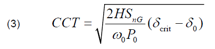
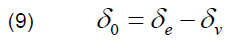
where: δ0 – rotor angle before the fault, SnG – nominal power of a generator, δcrit – critical value of rotor angle (rotor angle at the fault clearing time) is defined as follows:

where: PImax – maximum of a sine curve before a short-circuit.
Factors Affecting the Value of the CCT
Based on the above-mentioned relations, the value of the CCT is affected by:
• the value of voltage behind the transient reactance depending on the size of a rotor current, i.e., on the operating condition of a synchronous generator (under-excitation or over-excitation),
• the size of reactance, if reactance of the equipment (a generator, a block transformer, and a block power line) is considered constant, then the value of the CCT is affected by the size of the short-circuit reactance, i.e., the short-circuit power at the bus where the generator is connected,
• the size of the supplied active power of a generator before a short-circuit.
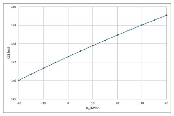
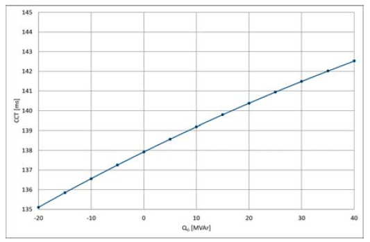
Impact of the size of the reactive power of a generator on the value of the CCT is depicted in figure 2 (generator in a nuclear power plant (NPP)), in figure 3 (generator in a combined cycle power plant (CCPP), in figure 4 (generator in a hydropower plant (HPP). The results refer to the generator’s constant active power and the constant short-circuit power (13856 MVA, respectively 20 kA). The results refer to the generators with the following parameters:
Table 1. The parameters of the generators
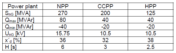
Table 2. The parameters of the block transformers

A significant parameter from the view of the dynamic stability is the inertia constant H. Inertia constant of large conventional units like, e.g., thermal, nuclear, and hydropower plants falls typically in the wide range of 2-9 s [7, 8]. It should be noted that current-day turbines and generators are generally lighter than the ones developed in the ’70s and ’80s, resulting in a lower H [9].
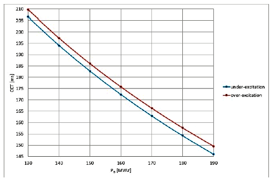
The results obviously indicate that under-excitation is more adverse from the view of the dynamic stability of a synchronous generator. The dependence of the value of the CCT on the produced active power is depicted in Fig. 5 – 7; the results refer to the maximum under-excitation of a generator and the maximum over-excitation.
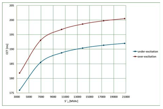
Fig. 8 – 10 depict the dependence of the CCT on the short-circuit power of the system; the results refer to the state of the maximum under-excitation of a generator and the maximum over-excitation, the constant active power.
The low value of the short-circuit power adversely affects the dynamic stability of a generator.


For online monitoring of power system dynamic stability, the value of the CCT needs to be defined for the system’s actual short-circuit power, the actually produced active, and
the generator’s reactive power.

Algorithm for online calculation of the CCT and possible operational measures for improvement of the indicator

Following equations are the tool to determine CCT value:

where: reactance x is in p.u.

where: current i is in p.u.
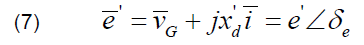
where: voltage e behind the transient reactance is in p.u.
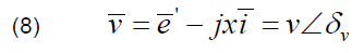
where: system voltage v behind the short-circuit reactance is in p.u.
where: δ0 is initial value of rotor angle.
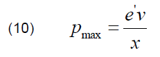
where: Pmax is maximum of P = f (δ) curve before a short circuit.

where: P0 is actual power of generator.
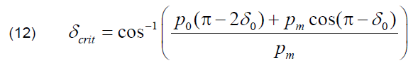
where: δcrit is critical rotor angle.
The proposed calculation of the CCT is simplified. The values of the CCT calculated in that manner may be considered a degree of stability or a trend in stability development.
Corrective Measures for Increase of the Value of the CCT
If the value of the CTT is lower than the required minimum value, corrective measures are necessary. The above-mentioned results and dependencies of the CCT indicate that corrective measures may be implied through the change of the produced power of a generator:
• increase of the produced reactive power
• decrease of the produced active power.
An increase of the produced reactive power may be achieved by increasing the voltage’s requested value at the terminals of a generator or in the pilot node within the secondary voltage control. If voltages are on the maximum of the permitted values, an increase of the reactive power of a generator is possible only if there is the possibility to turn on a compensating device – a shunt reactor.
A decrease of the produced active power may be achieved through a re-dispatch of the produced power between generators.
The Impact of Increase of Power in Distributed Generation in the DS and Development of Smart Grids on the Dynamic Stability of Generators
This part is dedicated to a possible impact of the current trend of increase of power in distributed generation in the distribution system, development of Smart Grids on the dynamic stability of generators, and the above-mentioned corrective measures for increasing the value of the CCT.
It can be assumed that the development of Smart Grids and the increase of power in distributed generation in the DS will enable the transfer of a significant part of the installed power into sources to a lower voltage level [10]. In this connection, it can be expected that a decrease in the number of sources and their power in the distribution system or interrupted operation of combined cycle power stations during working days will result in the change of operation and management of PS.
At the same time, a decrease in the number of operated generators in the transmission system connected with the proportion of installed power in the DS will result in a decrease of short-circuit power in the transmission system, which is affected especially by the deployment of generators in transmission systems (hereinafter referred to as “TS”) (contribution of a unit in a power plant 500 MW is appr. 2,5 kA) and topology of TS [11].
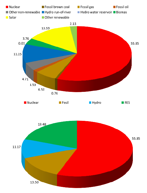
To illustrate the development of distributed generation in the DS, we refer to the current state in PS of the Slovak Republic. The share of installed power in RES (excluding hydropower plants) is 11,44 % only. Hydropower plants are not distributed sources in PS of the Slovak Republic. Their power (1200 MW) is exported to TS, and the remaining 1343 MW into the distribution system 110 kV and lower voltage levels. Installed powers in individual types of sources in PS of the Slovak Republic are depicted in Table 3. The share of installed power of individual types of sources is depicted in Fig. 11 [12].
Table 3. Installed power in PS of the Slovak Republic


In the spring months, there is usually a substantial production in PV (photovoltaic), a dominant distributed source in the DS of the Slovak Republic. Figure 12 depicts produced power in individual types of sources in April 2020 [13].
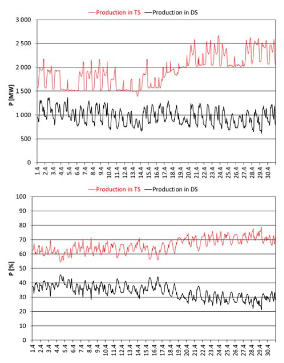
To document produced power in sources exported to TS and sources connected to the DS that month (April 2020), we provide graphs in Fig. 14. [14]
So far, there has not been a huge development of distributed production in the DS (share of installed power is 11,44 % only) in PS of the Slovak Republic. Despite the fact, production in the DS is significant at certain times of year (share up to 45 %).

Despite the development of Smart Grids and distribution sources in the DS, we assume that the existing transmission system remains operational. As a result of changes, the transmission system will be less loaded. The overpowering of the capacitive charging power of slightly loaded transmission lines ends in under-excitation or installing a shunt reactor. Excess reactive power develops in the DS if the installation of sources and spills of reactive power from the DS to TS through transmission transformers occur, thereby adversely affecting the situation in TS from the view of reactive power.
Fig. 15 depicts active and reactive power flow on transformers connecting TS and the DS of power in April 2020 [14]. The course of reactive power proves that during the entire month of April 2020 (when there was a significant production in sources of the DS), the reactive power flow was directed from the DS toward TS.
It follows from the above-mentioned that both analysed changes in PS: reduction of short-circuit power in the system and operation of generators connected in TS in the state of under-excitation negatively affect dynamic stability of generators operated in TS. That is the reason why online monitoring of the value of the CCT will take on increasing importance.
Corrective measure – an increase of a generator’s produced reactive power shall be more limited by lightly loaded transmission lines, and reactive power flows from the DS into TS.
Corrective measure – decrease in the produced active power of a generator will be, inter alia, limited by the number of generators operational in TS.
Conclusion
This work proposes the concept for online monitoring of power system dynamic stability based on the values of the CCT of individual generators. The given concept is simple and easy to implement in the dispatch control of PS. Values of the CCT calculated by applying a simplified way using a swing equation and the trend of the values may give basic information about a degree of power system dynamic stability to the transmission system operator. Basic input data (constant parameters of equipment and status variables) accessible to the operator are necessary for the proposed way of calculation of the CCT.
The work also addresses the analysis of factors influencing the value of the CCT. In particular, the low value of short-circuit power at the bus of connection of a generator into TS and operational state – under-excitation has a negative impact.
The above-mentioned factors and corrective measures were analysed from the view of current trends in change of the PS structure: increase of power of distributed production in the distribution system and development of so-called Smart Grids. They both anticipated changes in PS may be negatively perceived in the context of dynamic stability of synchronous generators operated in TS. Simultaneously, the use of corrective measures for the increase of the CCT will be limited by changes in PS structure. That is why online monitoring of the stability of PS will be even more important for the transmission system operator.
The impact of distributed production in the DS and Smart Grids on the existing overriding transmission system and generators running there will depend on the capability to shift production from TS to lower voltage levels of the DS. In addition to developing the concept of Smart Grids being a future of PS, it is vital and necessary to take the existing structure into account and prepare the operation of the transmission systems and large generators for a possible negative impact.
This paper was supported by the agency VEGA MŠVVaŠ SR under Grant No. 1/0640/17 “Smart Grids, Energy Self- Sufficient Regions and their Integration in Existing Power System”
REFERENCES
[1] V. Salehi, A. Mazloomzadeh, J. F. Fernandez and O. A. Mohammed, “Real-time power system analysis and security monitoring by WAMPAC systems,” 2012 IEEE PES Innovative Smart Grid Technologies (ISGT), Washington, DC, 2012, pp. 1-8, doi: 10.1109/ISGT.2012.6175768.
[2] W. Sattinger and G. Giannuzzi, “Monitoring Continental Europe: An Overview of WAM Systems Used in Italy and Switzerland,” in IEEE Power and Energy Magazine, vol. 13, no.5, pp. 41-48, Sept.-Oct. 2015, doi: 10.1109/MPE.2015.2431215.
[3] A. Suranyi, J. Bertsch and P. Reinhardt, “Use of wide area monitoring, protection and control systems to supervise and maintain power system stability,” The 8th IEE International Conference on AC and DC Power Transmission, London, UK, 2006, pp. 200-203, doi: 10.1049/cp:20060041.
[4] A. Siswanto, A. Suyuti, I. C. Gunadin, S. Mawar Said, “Steady State Stability Limit Assessment when Wind Turbine Penetrated to the Systems using REI Approach”, PRZEGLĄD ELEKTROTECHNICZNY, ISSN 0033-2097, R. 95 NR 6/2019.
[5] Y. Nakamura, N. Yorino, Y. Sasaki and Y. Zoka, “Transient stability monitoring and preventive control based on CCT,” 2018 International Symposium on Devices, Circuits and Systems (ISDCS), Howrah, 2018, pp. 1-6, doi: 10.1109/ISDCS.2018.8379650.
[6] Y. Kato and S. Iwamoto, “Transient stability preventive control for stable operating condition with desired CCT,” in IEEE Transactions on Power Systems, vol. 17, no. 4, pp. 1154-1161, Nov. 2002, doi: 10.1109/TPWRS.2002.805019.
[7] P. Anderson and A. Fouad, “Power system control and stability, ” Wiley – IEEE press, 2002.
[8] W. Stevenson and J. Grainger, “Power System Analysis, “New York: M`cGraw-Hill, 1994.
[9] P. Tielens, P. Henneaux and S. Cole, “Penetration of renewables and reduction of synchronous inertia in the European power system – Analysis and solutions.”, 2018. https://asset-ec.eu/
[10] Kamaruzzaman Z. A., Mohamed A. Static Voltage Stability Analysis in a Distribution System with High Penetration of Photovoltaic Generation. PRZEGLĄD ELEKTROTECHNICZNY ISSN 0033-2097, R. 91 NR 8/2015.
[11] J. Das, “Power system analysis, Short circuit, Load flow and Harmonics”. New York: Marcel Dekker, Inc., 2002. ISBN 0-8247-0737-0.
[12] Slovenská elektrizačná prenosová sústava, a.s., “Ročenka SED 2019”, available online at
https://www.sepsas.sk/Dokumenty/RocenkySed/ROCENKA_SED_2019.pdf
[13] Slovenská elektrizačná prenosová sústava, a.s., “Damas Energy”, available online at https://dae.sepsas.sk/
[14] Data provided by TSO of Slovak Republic Slovenská elektrizačná prenosová sústava, a.s.
Authors: doc. Ing. Žaneta Eleschová, PhD; prof. Ing. Anton Beláň, PhD; Ing. Matej Cenký, PhD.; Ing. Jozef Bendík, PhD.; Ing. Boris Cintula, PhD.; Ing. Peter Janiga, PhD., FEI Slovak University of Technology, Ilkovičova 3. 812 19 Bratislava, Slovakia, E-mail: zaneta.eleschova@stuba.sk
Source & Publisher Item Identifier: PRZEGLĄD ELEKTROTECHNICZNY, ISSN 0033-2097, R. 97 NR 6/2021. doi:10.15199/48.2021.06.23
