Published by Samira SEGHIR, Tahar BOUTHIBA, Université des Sciences et de la Technologie d’Oran Mohamed BOUDIAF, USTO-MB, Faculté de Génie Electrique, Laboratoire LGEO, BP 1505 El M’Naouer, 31000 Oran, Alegria
Abstract. A distance protection relay plays a major role in faults detection in the electric transmission line. The fault resistance has an effect on the fault location line and therefore the operation of a distance protection relay is not reliable. When a fault occurs in a transmission line, the current increases and the fault must immediately to be located and eliminated. Many methods have been used. In this work, a new method of compensation is proposed based on the fault impedance calculation to correct the performance of the distance relay. We use the Mho distance relay characteristics to protect the high voltage transmission lines by digital technology. The MATLAB software is used for modeling the relay characteristics. The aim of this article is to compare the results obtained by our proposed method with the traditional and resistance compensation methods.
Streszczenie. Przedstawiono nową metode obliczania impedancji spowodowanej uszkodzeniem w celu określenia lokalizacji tego błędu. Wykorzystano charakterystykę przekaźnika typu Mho do ochrony linii wysokiego napięcia metoda cyfrową. Porównano metodę z tradycyjną metoda bazującą na analizie rezystancji. (Metoda analizy impedancji w zastosowaniu do zabezpieczeń linii wysokiego napięcia)
Keywords: Transmission line protection, Fault location, Distance relay correction, Mho relay.
Słowa kluczowe: uszkodzenia linii wysokiego napięcia, lokalizacja uszkodzeń, analiza impedancji
Introduction
When the electrical fault occurs in transmission line, the distance protection is a main objective for the electrical network stability. The development of high-speed protection systems must meet these requirements.
The distance protection relay is designed to operate only for faults occurring in transmission line [1], [2], [3]. The distance relay calculate the impedance of the line permanently from the values of voltages and currents measured by the measurement transformers. This relay is based in percentages of impedances, which allowing locate the fault current and eliminate it.
When an electric fault appears on the line, an electric arc occurs, its resistance influences to locate this fault and may cause mal operation of the distance relay [4], [5].
Currently, the most used method of overhead line fault location is to determine the apparent reactance of the line during the time that the fault current is flowing and to convert the Ohmic result into a distance based on the parameters of the line [6], [7]. It is widely recognized that this method is subject to errors when the fault resistance is high and the line is fed from both ends.
Many compensation methods based on fault resistance calculation are used [4], [8]. An adaptive distance relaying scheme is used to eliminate the effect of fault resistance on distance relay zone reach. The fault resistance is calculated by using simple equation considering contribution from remote terminal current and equivalent sequence network [9], [10]. In [11] a compensation method based on fault resistance calculation is presented. The fault resistance calculation is based on monitoring the active power at the relay point.
In this paper, using a new proposed technique, the fault location in high voltage transmission line will be improved by decreasing the error caused by the arc resistance. This technique measure the correct value of impedance during the electrical fault by compensating the fault resistance effect. The proposed method corrects the line impedance from the distance relay to the fault point. We are going to apply this technique using the simple reactance method and the Takagi method. The obtained results of the developed algorithm is compared with the algorithm designed for standard and other proposed algorithm are included and discussed.
Principle and characteristic of mho distance relay
The mho relay measure the values of voltages and currents and permanently calculate the line impedance. It compare this impedance with the known impedance of the line, if it is inferior to the latter, a fault is detected. The relay give the order to the circuit breaker to open (see Figure 1).

The fault voltage Vs and fault current Is allows to measure the electric fault distance. In practice, the electric fault is not 100% located, due to the measurement errors, transformations errors, imprecision of the line impedance and the fault resistance.
The characteristic of the mho distance relay is a circular characteristic (see Figure 2).
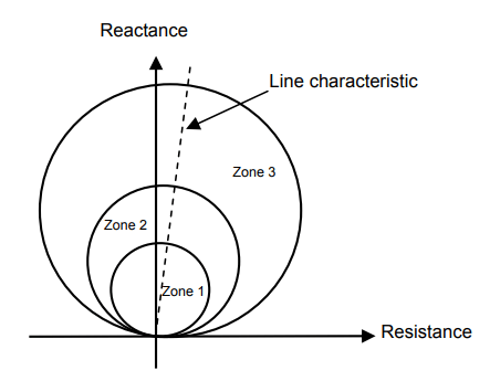
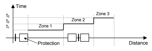
The line is divided into 3 zones where the 1st zone covers 80% of the line impedance, the 2nd zone covers 120% and the 3rd zone covers 150% with the assignment of a time delay to each zone. The electrical fault is eliminated after t1 if it occurs in zone 1, after t2 in zone 2 and after t3 in zone 3 (see Figure 3).
Fault location methods
There are many methods for locating faults occurring at a distance m in a transmission line [6], [7]. In this work, we assume that the current and voltage waves are sinusoidal after the fault. The signals are filtered and sampled. Two proposed methods, based on the use of measurements of the fundamental component of current and voltage signals at one end of the line, source S (see Figure 4).
From Figure 4, we can write the following equation:
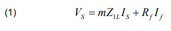
where Z1L, Rf, Is, Vs, If and m, are respectively the positive line impedance, fault arc resistance, current at source S, voltage at source S, fault current and fault location.
The value of the impedance Zapp measured from the source S can be determined by dividing the equation (1) by the measured current IS.

Fault location simple reactance method
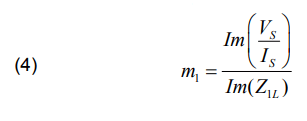
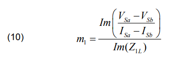
To minimize the effect of RfIf term, we take only the imaginary part of Zapp . Equation (2) can be written as follows [1], [6]:
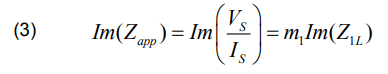
The fault location m1 using reactance method is expressed as follows:
A. Single-phase-to-ground fault
If the fault is considered in phase (a) with ground, the source current IS is given by the following expression:
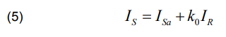
The residual current IR is given by
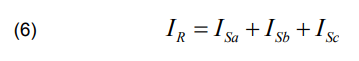
where ISa , ISb , ISc are respectively the current of phase (a), phase (b) and phase (c).
The ground factor k0 is given by:
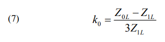
where Z0L is the zero sequence line impedance.
The calculation of fault location m1 is expressed as follows:

where VSa , VSb and VSc are respectively the simple voltage of phase (a), phase (b) and phase (c).
B. Phase-to-phase fault
If the fault is considered in phase (a) with phase (b), the fault location m1 is expressed by:

C. Three-phase fault
The fault location m1 is given by
Fault location Takagi method
The method requires pre-fault and fault data [7]. It improves upon the simple reactance method by reducing load flow effect and minimize the fault resistance effect.
We note that:
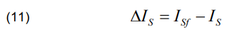
where ISf and IS are respectively the current fault at source S and the pre-current at source S.
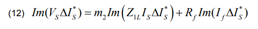
Multiply both sides of equation (1) by the complex conjugate of ΔIS and take the imaginary part we give:
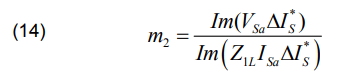
If the system is homogeneous, the angle of Is is the same as the angle of If . The calculation of fault location m2 using proposed method is expressed by:

A. Single-phase-to-ground fault
If the fault is considered in phase (a) with ground, the fault location m2 using proposed method is expressed as follows:
B. Phase-to-phase fault
If the fault is considered in phase (a) with phase (b), the fault location m2 is given by:

C. Three-phase fault
The fault location m2 can be written as follows:

Apparent impedance see by the conventional relay
The apparent impedance see by the conventional relay is expressed by:
The resistance and reactance see by the relay are:

where RArelay and XArelay are respectively the resistance and reactance calculated by the conventional numerical relay.
The resistance compensation method
This part presents the technics applied to compensate the fault resistance effect on the accuracy of impedance measurement. The process begins with determining the fault location during the occurrence of fault. The most used technique to locate the fault in a transmission line is a technique based on the impedance calculated from the measured currents and voltages.
We have presented previously the proposed method to locate the fault in transmission line.
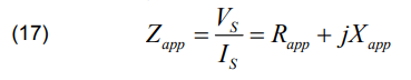
When the fault is localized, the relay calculate the fault resistance. The next step is to compensate the effect of this resistance in Mho distance relay. We first measure the apparent impedance at the relay point by using Equation (17). The measured apparent resistance Rapp and reactance Xapp are the real and imaginary values of impedance Zapp , respectively.
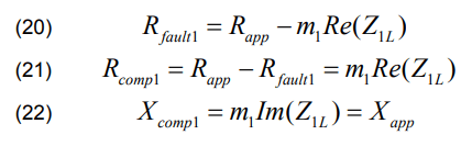
In order to compensate the apparent resistance Rapp , it will be subtracted with the fault resistance Rfault1 as shown in equation (21). The estimated fault resistance Rfault1, the compensated apparent resistance Rcomp1 and the compensated reactance Xcomp1 are given using the fault location m1 using fault location reactance method by the following expressions:
The resistance and reactance see by the relay are:
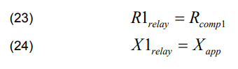
where R1relay and X1relay are respectively the resistance and reactance calculated by the relay using the reactance method.
The compensation is only on the resistance using the resistance method.
Proposed distance protection correction
This part presents the technic applied to compensate fault resistance and fault reactance effect on the accuracy of impedance measurement. The compensation is proposed on the resistance and the reactance using Takagi method.
In order to compensate the apparent resistance Rapp it will be subtracted with the fault resistance Rfault2 to obtain Rcamp2 as shown in equation (26) using fault location m2 calculated by Takagi method in equations (14) and (15).
The compensated reactance Xcamp2 as shown in equation (27), is calculated by using the fault location m2 .
The estimated fault resistance Rfault2 , the compensated apparent resistance Rcamp2 and the compensated reactance Xcamp2 are given using the proposed method by:

The resistance and reactance see by the relay are:

where R2relay and X2relay are respectively the resistance and reactance calculated by the relay using the proposed method.
Here, the compensation of resistance and reactance is used.
Simulation
The simulation and the protection algorithm were performed using the MATLAB software. The study network is carried out for two transmission lines with 400 kV double fed. The proposed transmission line to protect is 100 km and the adjacent line is also of 100 km. Source S and source R, are with resistance of 2.5 Ω and reactance of 9.42 Ω. The voltage phase of source S and source R, are respectively 0° and 20°. The circuit is presented in Figure 5.
The following Table 1 contains the parameters of the transmission lines.
Table 1. The parameters of the transmission lines
The zones of protection of the relay are defined at 80% of line 1 as zone 1, 100% of line 1 and 20% of line 2 as zone 2 and 100% of line 1 and 50% of line 2 as zone 3.
The faults were applied at several distances in the line from relay location with 20 Ω fault resistance (Rf). The first fault is applied at 70 km of the line situate in zone 1, the second in zone 2, is applied at 108 km of the line situate and the third is applied at 135 km of the line situate in zone 3.
Results and discussion
The results obtained are represented in the following for the two methods which we used two most frequent faults; single-phase fault and phase-to-phase fault.
A. Single-phase-to-ground fault
Figure 6 represents the results obtained by the relay for a single phase fault in zone 1. We can see that the fault resistance affects the distance protection (the fault is seen in zone 3), the relay cannot make a correct decision.

In this case, we can apply the compensation method for the correction of the distance protection, this method makes the distance relay more selective and instantaneous.
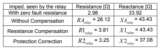
Figure 6 shows the result obtained by the relay when applied the resistance compensation method. We can see the fault is seen in zone 2 by the relay, the relay cannot make a correct decision. When applied the proposed method, we can see that the fault is seen in zone 1 by the relay and the relay make a correct decision. The proposed method can select the zone fault as indicated in Figure 6 and the fault is detected in zone 1. The final impedance values are shown in the Table 2.
Table 2. The final impedance values for a fault in zone 1

Figure 7 represents the results obtained by the relay for a single phase fault in zone 2. We can see that the fault resistance affects the distance protection (the fault is seen over zone 3), the relay cannot make a correct decision.
Figure 7 shows the result obtained by the relay when applied the resistance compensation method. We can see the fault is seen in zone 3 by the relay, the relay cannot make a correct decision. When applied the proposed method, we can see that the fault is seen in zone 2 by the relay and the relay make a correct decision. The final impedance values are shown in the Table 3.
Table 3. The final impedance values for a fault in zone 2

The proposed method can select the zone fault as indicated in Figure 7 and the fault is detected in zone 2.
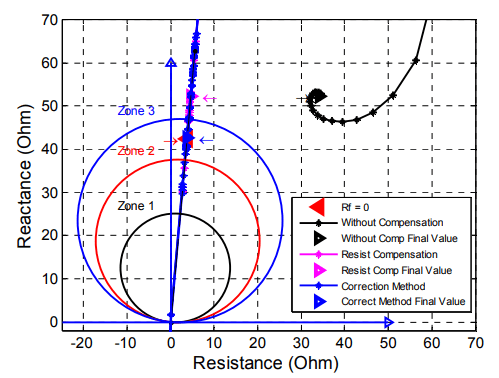
Figure 8 represents the results obtained by the relay for a single phase fault in zone 3. We can see that the fault resistance affects the distance protection (the fault is seen over zone 3), the relay cannot make a correct decision.
Figure 8 shows the result obtained by the relay when applied the resistance compensation method. We can see the fault is seen over zone 3 by the relay, the relay cannot make a correct decision. When applied the proposed method, we can see that the fault is seen in zone 3 by the relay and the relay make a correct decision. The proposed method can select the zone fault as indicated in Figure 8 and the fault is detected in zone 3.

The final impedance values are shown in the Table 4.
Table 4. The final impedance values for a fault in zone 3

B. Phase-to-phase fault
Figure 9 represents the results obtained by the relay for a double phase fault in zone 1. We can see that the fault resistance affects the distance protection (the fault is seen in zone 2), the relay cannot make a correct decision.
In this case, we can apply the compensation method for the correction of the distance protection, this method makes the distance relay more selective and instantaneous.
Figure 9 shows the result obtained by the relay when applied the resistance compensation method. We can see the fault is seen in zone 2 by the relay, the relay cannot make a correct decision. When applied the proposed method, we can see that the fault is seen in zone 1 by the relay and the relay make a correct decision. The proposed method can select the zone fault as indicated in Figure 9 and the fault is detected in zone 1.

The final impedance values are shown in the Table 5.
Table 5. The final impedance values for a fault in zone 1

Figure 10 represents the results obtained by the relay for a double phase fault in zone 2.

We can see that the fault resistance affects the distance protection (the fault is seen over zone 3), the relay cannot make a correct decision.
Figure 10 shows the result obtained by the relay when applied the resistance compensation method. We can see the fault is seen in zone 3 by the relay, the relay cannot make a correct decision. When applied the proposed method, we can see that the fault is seen in zone 2 by the relay and the relay make a correct decision. The proposed method can select the zone fault as indicated in Figure 10 and the fault is detected in zone 2. The final impedance values are shown in the Table 6.
Table 6. The final impedance values for a fault in zone 2

The final impedance values are shown in the Table 7.
Table 7. The final impedance values for a fault in zone 3

Figure 11 represents the results obtained by the relay for a double phase fault in zone 3. We can see that the fault resistance affects the distance protection (the fault is seen over zone 3), the relay cannot make a correct decision.
Figure 11 shows the result obtained by the relay when applied the resistance compensation method. We can see the fault is seen over zone 3 by the relay, the relay cannot make a correct decision. When applied the proposed method, we can see that the fault is seen in zone 3 by the relay and the relay make a correct decision. The proposed method can select the zone fault as indicated in Figure 11 and the fault is detected in zone 3.
Conclusion
In case of arc fault, the operation of the distance protection relay is examined. It shows that if an arc fault occurs at the end of each zone, for example zone 1, the distance relay will take the error on the fault location and see the fault in the second or the third zone, so that the relay cannot work selectively and instantaneously. We proposed a method to correct the distance protection relay. This method gives good results and makes distance protection more selective and instantaneous compared with traditional and resistance compensation methods.
REFERENCES
[1] Ziegler G., Numerical Distance Protection-Principles and Applications, 4th updated and enlarged edition, Publicis Publishing, 2011.
[2] Adam BACHMATIUK, Jan IŻYKOWSKI “Distance protection performance under inter-circuit faults on double-circuit transmission line,” PRZEGLĄD ELEKTROTECHNICZNY, ISSN 0033-2097, R. 89 NR 1a/2013, pp. 7-11.
[3] Justyna HERLENDER, Krzysztof SOLAK, Jan IŻYKOWSKI, “Impedance-Differential Protective Algorithm for Double-Circuit Transmission Lines,” PRZEGLĄD ELEKTROTECHNICZNY, ISSN 0033-2097, R. 95 NR 11/2019, pp. 240-244.
[4] D. L. Waikar, S. Elangovan, and A. C. Liew, “Fault impedance estimation algorithm for digital distance relaying,” IEEE Trans. Power Del., vol. 9, no. 3, pp. 1375–1383, Jul. 1994.
[5] S. Horowitz and A. Phadke, Power System Relaying. Baldock, Hertfordshire, U.K.: Research Studies Press, 1995.
[6] Murari Mohan Saha, Jan Izykowski and Eugeniusz Rosolowski, “Fault Location on Power Networks”, Springer London Ltd, 2009.
[7] T. Takagi, Y. Yamakoshi, M. Yamaura, R. Kondou, and T. Matsushima, “Development of a New Type Fault Locator Using the One-Terminal Voltage and Current Data,” IEEE Transactions on Power Apparatus and Systems, Vol. PAS-101, No. 8, August 1982, pp. 2892-2898.
[8] André Darós Filomena, Rodrigo Hartstein Salim, Mariana Resener, and Arturo Suman Bretas,” Ground Distance Relaying With Fault-Resistance Compensation for Unbalanced Systems,” IEEE Trans. Power Del., VOL. 23, NO. 3, July 2008, pp. 1319-1326.
[9] Muhd Hafizi Idris, Mohd Saufi Ahmad, Ahmad Zaidi Abdullah, Surya Hardi, “Adaptive Mho Type Distance Relaying Scheme with Fault Resistance Compensation,” 7th International Power Engineering and Optimization Conference (PEOCO2013), Langkawi, Malaysia. 3-4 June 2013, pp. 208-212.
[10] H. Seyedi L. Behroozi, “New distance relay compensation algorithm for double-circuit transmission line protection,” IET Gener. Transm. Distrib. , 2011, Vol. 5, Issue 10, pp. 1011–1018.
[11] M. M. Eissa “Ground Distance Relay Compensation Based on Fault Resistance Calculation,” IEEE Trans. Power Del., VOL.21, NO. 4, October 2006, pp. 1830-1835.
Authors: Samira Seghir was born in Algiers, Algeria, on August, 9, 1991. PhD at University of Sciences and Technology of Oran, Algeria. Faculty of Electrical Engineering, Oran Electrical Engineering Laboratory (LGEO). His scientific interests include the fault location in transmission line, dynamic arc fault simulation and numerical relay for transmission line protection, E-mail: seghirsamira3@gmail.com.
Tahar Bouthiba is currently Professor of electrical engineering and a lecturer at the University of Science and Technology of Oran city, Algeria. His research interests include computer relaying and control switching using digital techniques and artificial intelligence, E-mail: tbouthiba@yahoo.com
Source & Publisher Item Identifier: PRZEGLĄD ELEKTROTECHNICZNY, ISSN 0033-2097, R. 97 NR 1/2021. doi:10.15199/48.2021.01.04
