Published by 1. S. Abdul Rahman, 2. Estifanos Dagnew Mitiku, 3. Shumye Birhan Mule, 4. Gebrie Teshome Aduye, 5. Mekete Asmare Huluka, 6. Solomon Mesfin Institute of Technology, University of Gondar, Ethiopia
Abstract – Dynamic voltage restorer is considered to be one of the best device to compensate voltage sag and swell. Recently the DVRs based on direct converters are very popular and works are getting published for various topologies and modulating techniques to explore the efficiency and worth of the same. In this paper, the direct converter is realized using only two bidirectional switches, in order to mitigate voltage sag. The voltage required to compensate the voltage sag is taken from the same phase where the voltage sag has occurred. The direct converter is connected between the line in which the voltage sag has occurred and the series transformer. In the conventional PWM generation technique, the supply voltage is measured and compared with the reference voltage in order to find out the voltage sag and the error voltage signal. This error signal will be compared with the carrier to generate the PWM pulses. Though already papers have been published to mitigate voltage sag using direct converter, in this paper, as one of the efforts to show the flexibility of the direct converter based DVR, the voltage sag is mitigated without measuring the supply voltage and without generating the error signals, since the power required to mitigate the sag is taken from the phase where it occurred. Ordinary PWM technique is used to control the bidirectional switches. In this proposed methodology the DVR is able to compensate 22% of voltage sag. The simulation is carried out in Matlab Simulink and the results are presented for verification.
Streszczenie – Dynamiczny restorer napięcia jest uważany za jedno z najlepszych urządzeń do kompensacji zapadów i wzrostów napięcia. Ostatnio bardzo popularne są rejestratory DVR oparte na konwerterach bezpośrednich i publikowane są prace dla różnych topologii i technik modulacji w celu zbadania ich wydajności i wartości. W niniejszym artykule przekształtnik bezpośredni jest realizowany przy użyciu tylko dwóch dwukierunkowych przełączników, w celu złagodzenia zapadu napięcia. Napięcie wymagane do skompensowania zapadu napięcia jest pobierane z tej samej fazy, w której wystąpił zapad napięcia. Przetwornik bezpośredni jest podłączony między linią, w której wystąpiło zapad napięcia, a transformatorem szeregowym. W konwencjonalnej technice generowania PWM napięcie zasilania jest mierzone i porównywane z napięciem odniesienia w celu określenia zapadu napięcia i sygnału błędu napięcia. Ten sygnał błędu zostanie porównany z nośnikiem w celu wygenerowania impulsów PWM. Chociaż opublikowano już artykuły mające na celu złagodzenie zapadu napięcia za pomocą bezpośredniego konwertera, w tym artykule, jako jeden z wysiłków mających na celu pokazanie elastyczności rejestratora opartego na bezpośrednim konwerterze, zapad napięcia jest łagodzony bez pomiaru napięcia zasilania i bez generowania sygnałów błędu , ponieważ moc wymagana do złagodzenia zwisu jest pobierana z fazy, w której wystąpił. Do sterowania przełącznikami dwukierunkowymi wykorzystywana jest zwykła technika PWM. (Łagodzenie zapadów napięcia za pomocą DVR opartego na bezpośrednim konwerterze bez sygnału błędu)
Key Words – Dynamic Voltage Restorer, Voltage Sag, Direct Converter, Series Transformer, Mat lab Simulink, Without Error Signal
Słowa kluczowe – Dynamiczny przywracanie napięcia, zapad napięcia, konwerter bezpośredni, transformator szeregowy, bez sygnału błędu
Introduction
To mitigate power quality issues like voltage sag, swell, flicker, harmonics, etc. [1], we have many devices both on the transmission side and distribution side. Flexible AC devices are used on transmission side [2] while Custom Power Devices are used on distribution side [3, 4] to improve the power quality of the power system. On distribution side we have devices like UPS, static transfer switch, motor-generator set, shunt active filters and DVR [5]. The DVR considered to be a most efficient and economic device to improve the power quality on the distribution side as it works when there is power quality issue arises, occupies less space, less weight, less maintenance, etc [6-9].
DVR is a series compensator, which is used to add the compensating voltage in series with the line voltage in order to mitigate voltage sag, swell, harmonics, flicker, etc. A conventional DVR has an energy storage device ( which may be a battery bank or capacitor or super capacitor), an inverter to convert the DC power in the energy storage device to AC power and a series transformer to inject the AC power generated by the inverter, in series with the line voltage. When a power quality issue occurs on the supply side, the inverter synthesis the required compensating voltage by taking power from the energy storage devices and injects the compensating voltage in series with the line voltage using the series transformer [10-12]. The compensating range and duration of mitigation of voltage sag and swell, of this topology is based on the rating of the energy storage devices. This conventional DVR has disadvantages like heavy weight, volume, uneconomical, more maintenance due to the presence of energy storage devices [13-15]. In order to overcome, these disadvantages, recently DVRs based on direct converters are proposed. In this topology, the energy storage devices are not used. Instead the power taken from the supply side itself to mitigate the power quality issues. As the power is taken form the supply side to mitigate the power quality issues, this topology uses direct converters to synthesis the compensating voltage. A series transformer is used to inject the output voltage of the direct converter, in series with the line voltage. So when a voltage sag or swell occurs, the direct converter will synthesis the required compensating voltage by taking power from the supply side and the compensating voltage is added in series with the line voltage using the series transformer . As this topology didn’t used energy storage devices, it is not having disadvantages like topology based on energy storage devices. The compensating range and the mitigating duration of this topology is based upon the direct converter topology, modulating techniques and the availability of input voltage for the direct converter [16-20].
In the literature, very few publications are available for the DVRs based on the direct converters as it is a recent technique. Out of those publications, the topology presented in [21, 22] can mitigate 50% of voltage sag and 100% of swell by taking power from the same phase. The topologies presented in [23, 24] can mitigate 33% of voltage sag and 100% of voltage swell by taking power form the different phases. Though the topologies in [25-27] are based on direct converters, they can mitigate voltage sag, swell and also single outage. Based on the modulating techniques, the voltage sag and swell compensating range could be improved is proved in [28, 29]. So far in all the DVR topologies based on either direct converters or energy storage devices, the voltage sag is mitigated by measuring the supply voltage and comparing it with the reference signal. From the comparison, error signal will be generated and this error signal will be compared with the carrier signal to generate the PWM pulses to control the switches to synthesis compensating voltage. In this paper, mitigation of voltage sag without generation of error signal is proposed as this topology is based on direct converter and it is taking power from the same phase to mitigate voltage sag and swell.
Topology and control algorithm of the DVR
The DVR consists of a direct converter with two bidirectional switches Sa and Sg, LC filter and a series transformer of turns ratio 1:1. For simplicity only one phase is considered out of three phases as power is taken from the same phase to mitigate the voltage sag.

In the conventional control algorithm, the RMS value or the peak value of the supply voltage is measured and subtracted from the rated voltage. From this comparison error signal will be obtained. This error signal is converted into per unit value and then compared with the carrier signal to generate the PWM pulses for the switches. In this proposed control algorithm, a potential transformer (PT) is used to step down the supply voltage. The turns ratio of the PT is peak value of the supply voltage to 1. For example if the supply side rated peak voltage is (rms 220 v) 311 volts then turns ratio of the transformer is 311:1. If the supply side rated peak voltage is (rms 110)156 volts then the turns ratio of the transformer is 156:1. So the output voltage of the PT is in per unit value expressed in percentage of the rated supply voltage. The output voltage of the PT is rectified using a full wave uncontrolled rectifier and filtered using LC filter of value 2 milli Hendry and 15 micro farad. The output is a pure DC voltage which is compared with the carrier signal of 4000 Hz. It is better to use a precision uncontrolled full wave rectifier (using operational amplifiers in actual practice), as the ordinary full wave uncontrolled rectifier (using diodes) is having voltage drop across the diodes while rectification. The amplitude of the carrier signal is 1 per unit.
In the conventional PWM generation, the supply voltage is measured. By comparing the supply voltage magnitude with the reference signal, error signal is generated. This error signal is compared with the carrier signal to generate the PWM for the switches. When the error signal is more than or equal to the carrier signal, the PWM will be in ON state. Otherwise the PWM will be in off state.
In the proposed algorithm, the supply voltage is not measured and it is not compared with the reference signal. But the supply voltage is stepped down to 1 per unit using a potential transformer, and rectified using a uncontrolled precision rectifier. The carrier signal amplitude is kept at 1 per unit.
Under normal condition, when the supply voltage is at rated value, the DVR should be in off condition. i.e. the switch Sg should be in closed condition and Sa should be in open condition. When the supply voltage is at rated value, the output voltage of the rectifier is at 1 volt. The magnitude of the carrier signal is also at 1 unit. The PWM will be generated when the carrier is more than the rectifier output voltage. Under normal condition, the magnitude of both carrier signal and the rectifier output voltage are equal to 1. So the PWM will not be generated or the duty ratio of the PWM is zero. This PWM signal is given to the switch Sa and the same signal is complimented using a NOT gate and given to the switch Sg. The switch Sa is open and the switch Sg is closed. The secondary of the series transformer is short circuited and the injected voltage is zero. The load voltage is maintained at the rated value as the supply voltage is also at rated value.
When a voltage sag occurs, the supply voltage will be less than 1 per unit. The magnitude of the carrier is 1 per unit. As the supply voltage magnitude is less than the carrier magnitude, PWM will be generated according to the magnitude of voltage sag at the supply side. The generated PWM signals are given to the switches Sa and Sg using a NOT gate. According to the percentage of voltage sag, the supply voltage magnitude changes, the magnitude of the rectified voltage signal also changes, which in turn changes the duty ratio of the PWM signals. So the compensating voltages are generated according to the occurrence of voltage sag. The generated compensating voltage is injected using a series transformer in phase with the supply voltage to mitigate the sag. In this paper, the reference signal is not created. Supply voltage is not measured and not subtracted from the reference signal. This compensation technique is achievable using only analog circuits without embedded systems.
Simulation results
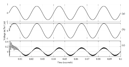
The rated supply voltage is chosen as 230V RMS, the turns ratio of the potential transformer is 325:1V, switching frequency of the carrier is 4000 Hz, inductance and the capacitance of the filter is 2 milli Hendry and 15 micro Farad and the turns ratio of the series transformer is 1:1. When the supply voltage is at rated condition, the DVR should not generate any compensating voltage. The switch Sg should be closed and the switch Sa should be open and the compensating voltage injected through the series transformer should be zero. This s shown in the figure 2. From the result shown in the figure 2, it could be observed that the compensating voltage generated by the DVR is equal to zero and load voltage is maintained at 1 per unit without harmonics. Figure 3 shows the voltage sag compensation when the supply voltage has a sag of 10%. The switches Sa and Sg are alternatively modulated in order to synthesis the required compensating voltage and the compensating voltage is added in phase with the supply voltage through the series transformer.
Voltage sag compensation of 15% is shown in the figure 4. It is observed that though the supply voltage is at 0.85 per unit, the load voltage is maintained constant at 1 per unit, as the DVR has generated the required compensating voltage in phase with the supply voltage as shown in the figure 4c.
Figure 5 shows the voltage sag compensation of 20%. It could be observed that the load voltage is maintained constant at 1 per unit. The highest compensating capacity of 22% voltage sag is shown in the figure 6. It could be observed that the supply voltage is at 0.88 per unit but the load voltage is maintained constant at 1 per unit by the compensating voltage synthesized by the DVR. The THD of the compensated load voltage is found to be less than 1% from 0% voltage sag to 22% voltage sag.


Conclusion
In this paper, a DVR based on direct converter is realized with only two bidirectional switches to mitigate the voltage sag. As the number switches used are only two, generation of PWM pulses to control the switches are very easy and less switching losses. Though many other DVR based on direct converters are already proposed for the mitigation of voltage sag, in all the works, an embedded system is required to measure the supply voltage, compare with the reference signal to generate the error signal and to generate the PWM pulses for the switches by comparing the error signal with the carrier signal. But in this paper the supply voltage is not measured and not compared with the reference signal to generate the error signal. Instead a new control algorithm is proposed, in which the supply voltage is expressed in per unit using a potential transformer and uncontrolled rectifier. The output of the uncontrolled rectifier is compared directly with the carrier signal to generate the PWM pulses for the switches and to generate the compensating voltages. With the proposed control methodology, embedded systems are not necessary but analog circuits are more than enough to synthesis the compensating voltages. From the simulation results it could be observed that proposed system can mitigate a voltage sag of 22% with the THD less than 1%.
REFERENCES
[1] Amr Abou-Ghazala , Ashraf Megahed , Ahmed Hassan : Mitigation of Steel Making Plants’ Electrical Power Quality Problems Using SVC – A Case Study, Przegląd Elektrotechniczny, 7, 2016.
[2] Paweł Kostyła , Jacek Rezmer , Adam Gubański , Jarosław Szymańda : Synthetic indices for power quality assessment for distributed generation, Przegląd Elektrotechniczny, 10/2017.
[3] Zbigniew Hanzelka , Andrzej Firlit , Bogusław Świątek , Krzysztof Piątek , Mateusz Dutka , Tomasz Siostrzonek : Analysis of selected power quality indicators at non-measured distribution network points based on measurements at other points, Przegląd Elektrotechniczny, 05/2020
[4] PA Janakiraman, SA Rahman, Linear pulse width modulation under fluctuating power supply, IEEE Transactions on Industrial Electronics, 61 (4), 1769-1773.
[5] Sunita Kumari, Sudhir Y Kumar, Design Analysis and Development of Inverter Topologies for Industries, Indonesian Journal of Electrical Engineering and Informatics, vol 6, No 1: March 2018.
[6] Miska Prasad, Ashok Kumar Akella, Performance Evaluation of Three Different Inverter Configurations of DVR for Mitigation of Voltage Events, Indonesian Journal of Electrical Engineering and Informatics, vol 4, No 4: December 2016.
[7] Ali Basim Mohammed, et al., “Power quality improvement using dynamic voltage restorer in electrical distribution system: an overview,” Indonesian Journal of Electrical Engineering And Computer Science, vol 17, no.1, January 2020.
[8] Syed Suraya, P. Sujatha and P. Bharat Kumar, “Contemporary Control of DG Integrated DVR for Sag, Swell and Harmonic Mitigation,” International Journal of Electrical and Computer Engineering, vol 8, no 5, October 2018.
[9] Awais Farooqi, et al, “Mitigation of power quality problems using series active filter in a microgrid system,” International Journal of Power Electronics and Drive Systems, vol 10, no 4, December 2019.
[10] S Rahman, Shumye Birhan Mule, Estifanos Dagnew Mitiku, Gebrie Teshome Aduye, C Gopinath. Highest Voltage Sag and Swell Compensation using Single Phase Matrix Converter with Four Controlled Switches, Przegląd Elektrotechniczny, 97, 4/2021, doi:10.15199/48.2021.04.24.
[11] Amirullah Amirullah, Ontoseno Penangsang and Adi Soeprijanto, “Matlab/simulink simulation of unified power quality conditioner-battery energy storage system supplied by PV-wind hybrid using fuzzy logic controller,” International Journal of Electrical and Computer Engineering, vol 9, no 3, June 2019.
[12] Jiangfeng Wang, Yan Xing, Hongfei Wu and Tianyu Yang, “A Novel Dual-DC-Port Dynamic Voltage Restorer with ReducedRating Integrated DC-DC Converter for Wide-Range Voltage Sag Compensation,” IEEE Transactions on Power Electronics, vol. 34, no. 8, 2019.
[13] Abdul Rahman, “Realization of Single Phase Matrix Converter Using 4 Controlled Switches,” International Journal of Engineering, Applied and Management Sciences Paradigms, vol. 54, no. 7, 2019.
[14] R. Omar and N. A. Rahim, “Voltage unbalanced compensation using dynamic voltage restorer based on supercapacitor,” International Journal of Electrical Power & Energy Systems, vol. 43, no. 1, December 2012.
[15] Toufik Toumi, et al, “PV integrated single-phase dynamic voltage restorer for sag voltage, voltage fluctuations and harmonics compensation,” International Journal of Power Electronics and Drive Systems, vol. 11, no. 1, March 2020.
[16] Suma Jothibasu and Mahesh K. Mishra, “A Control Scheme for Storage less DVR Based on Characterization of Voltage Sags,” IEEE Transactions on Power Delivery, vol. 29, no. 5, 2014.
[17] PA Janakiraman, S Abdul Rahman, “Linear pulse width modulation under fluctuating power supply,” IEEE Transactions on Industrial Electronics, vol. 61, no 4, pp. 1769-1773, 2013.
[18] Prasai, and D.M. Divan, “Zero-energy sag correctorsOptimizing dynamic voltage restorers for industrial application,” IEEE Trans. Ind. Appl., vol. 44, no. 6, pp. 1777-1784, 2008.
[19] SA Rahman, S Birhan, ED Mitiku, GT Aduye, P Somasundaram, A Novel DVR Topology to Compensate Voltage Swell, Sag, and Single-Phase Outage, Iranian Journal of Electrical and Electronic Engineering, 17 (4), 2036-2036.
[20] E. Babaei, M.F. Kangarlu, and M. Sabahi, “Mitigation of Voltage Disturbances Using Dynamic Voltage Restorer Based on Direct Converters,” IEEE Transactions on Power Delivery, vol. 25, no. 4, pp. 2676-2683, 2010.
[21] Abdul Rahman Syed Abuthahir, Somasundaram Periasamy, Janakiraman Panapakkam Arumugam, “Mitigation of Voltage Sag and Swell Using Direct Converters with Minimum Switch Count,” Journal of Power Electronics, vol. 14, no. 6, pp. 1314-1321, 2014.
[22] S. Abdul rahman, and P. Somasundaram, “Mitigation of Voltage Sag and Swell Using Dynamic Voltage Restorer without Energy Storage Devices,” International Review of Electrical Engineering, vol. 7, vo.4, pp. 4948-4953, 2012.
[23] S. Abdul Rahman, P.A. Janakiraman and P. Somasundaram, “Voltage sag and swell mitigation based on modulated Carrier PWM,” International Journal of Electrical Power and Energy Systems, Elsevier, vol. 66, pp. 78-85, 2015.
[24] S. Abdul Rahman and P. Somasundaram, “Voltage sag and swell compensation using AC/AC converters,” Australian Journal of Electrical & Electronics Engineering, vol. 11, no. 2, pp.186-194, 2014.
[25] S. Abdul rahman, “Direct Converter Based DVR to Mitigate Single Phase Outage,” International Journal of Recent Technology and Engineering (IJRTE), vol. 8, no.3, pp.85-88, September, 2019.
[26] Abdul Rahman, “Mitigation of Voltage Sag, Swell and Outage without Converter,” International Journal of Latest Transactions in Engineering and Science (IJLTES), vol. 8, no. 1, 2019.
[27] Abdul Rahman, “Mitigation of Single Phase Voltage Sag, Swell and Outage Using Voltage Controlled Voltage Source,” Global scientific Journal, vol. 7, no. 10, 2019.
[28] S. Abdul Rahman, Gebrie Teshome, “Maximum voltage sag compensation using direct converter by modulating the carrier signal,” International Journal of Electrical and Computer Engineering (IJECE), vol. 10, no. 4, 2020.
[29] S. Abdul Rahman, Estifanos Dagnew, “Voltage sag compensation using direct converter based DVR by modulating the error signal,” Indonesian Journal of Electrical Engineering and Computer Science, Vol 19, No 2: August 2020.
Source & Publisher Item Identifier: PRZEGLĄD ELEKTROTECHNICZNY, ISSN 0033-2097, R. 97 NR 12/2021. doi:10.15199/48.2021.12.05
