Published by 1. Oleg GUBAREVYCH1, 2. Svitlana GOLUBIEVA1, 3. Inna MELKONOVA2, State University of Infrastructure and Technologies (1), Volodymyr Dahl East Ukrainian National University (2)
ORCID: 1. 0000-0001-7864-0831; 2. 0000-0001-8285-7566; 3. 0000-0001-6173-1470
Abstract. The paper presents the results of a comparison of the electrodynamic and energy characteristics and parameters of an asynchronous motor, obtained by simulation and calculated by the classical method. The mathematical model in the MATLab software environment is used for research. The research results are relevant when choosing and using the proposed simulation model of three-phase squirrel-cage asynchronous motors for further research, including the effect of various engine defects on its performance
Streszczenie. W artykule przedstawiono wyniki porównania charakterystyk i parametrów elektrodynamicznych i energetycznych silnika asynchronicznego, uzyskanych metodą symulacji i obliczonych metodą klasyczną. Do badań wykorzystano model matematyczny wykonany w środowisku oprogramowania MATLab. Wyniki prac mają istotne znaczenie dla wyboru i wykorzystania zaproponowanego modelu symulacyjnego asynchronicznego silnika elektrycznego z wirnikiem klatkowym do dalszych badań, w tym wpływu różnego rodzaju uszkodzeń silnika na jego pracę. (Porównanie wyników modelowania symulacyjnego asynchronicznego silnika elektrycznego z obliczonymi charakterystykami elektrodynamicznymi i energetycznymi)
Keywords: asynchronous motor, simulation modeling, charakterystyka elektrodynamiczna, mathematical model.
Słowa kluczowe: silnik asynchroniczny, modelowanie symulacyjne, electrodynamic characteristics, model matematyczny
Introduction
Improving the operational reliability of electromechanical equipment is a modern priority task, the solution of which determines the result of the efficient operation of industrial and transport enterprises. Three-phase squirrel-cage asynchronous motors are among the most common electrical machines used to drive various mechanisms in all industries. Currently, almost 70% of the machines used in industry are three-phase asynchronous motors because they are simple, reliable and inexpensive [1]. The requirements for each technological process determine the need to set and maintain the operating parameters of the motors used with high accuracy at a given level. Many malfunctions and defects that occur in difficult operating conditions quickly progress and disable electric motors, even with a short service life, leading them to an emergency stop. Timely and reliable detection of damage not only increases the reliability of motors, but significantly reduces repair time and reduces unforeseen costs. Experience in the operation of asynchronous electric motors shows that the development and implementation of modern diagnostic tools based on a thorough study of the processes occurring when defects occur is one of the most important and effective factors in increasing the economic efficiency of using electromechanical equipment in industry [2, 3].
Determining the type and degree of damage, establishing their influence on the performance of electric motors, improving the accuracy of predicting the final resource and uptime is possible on the basis of studying electrodynamic processes that occur in the presence of defects of various kinds [4-6]. Mathematical modeling methods are widely used to conduct research in various fields [7-9]. Simulation models of asynchronous electric motors for the correct use of the results in improving diagnostic systems and studying processes occurring at different degrees of defects must be checked for compliance with the properties of the simulated object to real processes. The results of simulation modeling are of an estimated nature and require further verification, in particular, by conducting full-fledged experimental studies on real objects. Given that experimental studies are highly laborious, the paper proposes an approach to evaluating the results of simulation modeling by comparing them with a set of calculated energy and electrodynamic indicators of an asynchronous motor.
The aim of the article is to conduct a study on the evaluation of the selected mathematical model of an asynchronous motor by com-paring the results of simulation modeling and the electrodynamic characteristics and energy parameters calculated by the classical method. The use of a mathematical model with the established accuracy of the results of simulation modeling in further research will allow more correct consideration of the influence of defects in the operation of asynchronous motors to determine the method for their diagnosis and assessment of the degree of damage and study of the ongoing electrodynamic processes.
To achieve the aim, the following tasks were completed:
– the parameters and performance characteristics of the selected base motor were calculated according to the classical method;
– simulation modeling in the MATLab software environment of the operation of an asynchronous motor was carried out using the selected mathematical model;
– obtained as a result of mathematical modeling electrodynamic characteristics and energy parameters of an asynchronous electric motor;
– a comparison of the results of modeling and calculations using the electrodynamic characteristics of an asynchronous electric motor was carried out.
Choice of a model for the study of electrodynamic processes and the basic type of motor
The statistics of operating experience of asynchronous motors shows that the largest share of operability failures is due to failures in the stator and, according to various data, taking into account the operating area, 77-85%, the rotor accounts for 6-8% and the bearing assembly – up to 8-14% [1, 3, 10]. The main part of the defects in the motor leads to the occurrence of an asymmetric rotating stator field. Therefore, to conduct a study on the manifestation of a larger range of damage, it is necessary to use a reliable mathematical model of an asynchronous motor with the possibility of research, including under asymmetric modes that occur during operation with various types of stator defects [11-13].
To conduct research on electromagnetic processes, there are a large number of approaches to simulation modeling of asynchronous motors. Their differences are mainly related to the choice of the coordinate system in which differential equations are composed that describe the operation of an asynchronous motor. In works [6, 11], a model is considered in which the equations de-scribing the operation of an asynchronous motor are written in d-q coordinates, i.e. in a single-phase coordinate system. When using such a model, it becomes difficult to determine some parameters, for example, the imbalance of phase currents, which is necessary for diagnosing a number of defects. When modeling asynchronous motors with asymmetric windings, it is advisable to use a system of differential equations in hindered coordinates, as noted in [14]. To solve the problem, the use of other coordinate systems is incorrect. This is evidenced by studies in [15, 16].
To implement the simulation modeling of the operation mode of an asynchronous motor with asymmetrical windings, which occurs in the event of damage to one or more stator windings, one should set a change in the leakage inductance and active resistance of the corresponding winding (windings). That is, it is necessary to establish how much the actual values of the specified parameters differ from the nominal values. After that, take into account how the mutual inductance of the windings will change. To determine the change in the mutual inductance of the windings, it is necessary to establish what effect the change in the complex resistance of one winding (several windings) has on the inductance of the magnetic circuit. The papers [17, 18] show the established relationship between the winding inductances and the geometric dimensions of the windings, which must be taken into account when simulation modeling.
Thus, in order to conduct further research with a wider range of possible defects that affect the operating modes of motors, it is necessary to use a mathematical model of an asynchronous motor with the possibility of creating an asymmetric rotating field, made in “braking coordinates”, taking into account losses in steel and mechanical losses. In addition, for the implementation of this modeling principle, one should take into account the mutual inductance of the windings when the complex resistance of one or more phases of the stator winding, simulating its damage, changes. When determining the change in the mutual inductances of the windings, it is necessary to determine what effect the change in the complex resistance of one winding (two windings) has on the inductance of the magnetic circuit and establish the relationship between the inductances of the windings and the geometric dimensions of the windings, as well as the effect on the leakage inductance of each phase and mutual phase inductances.
The simulation model of an asynchronous motor proposed and used in the work, for which the reliability of real processes is established, is made in “braked coordinates”. The general view of the model and its implementation in the MATLab software environment are presented and discussed in detail in [19]. The implementation of the mathematical model [19] based on the configuration of mutual inductance with a change in the complex resistance of one or more phases of the motor is considered in [20]. This model can be adapted to study the operation of an asynchronous motor when such a defect occurs in it as an interturn short circuit of the stator windings, which entails an asymmetric rotation field, as well as to determine the starting and operating characteristics of the motor, calculate energy indicators when the asynchronous motor is operating with the specified defect. Thus, simulation modeling of an asynchronous electric motor was carried out using a mathematical model given and discussed in detail in [20].
The simulation model of an asynchronous motor, made in the MATLab software environment, is shown in fig. 1. The following parameters are displayed: stator phase voltages, stator phase currents, rotor phase currents, motor shaft speed and useful motor shaft torque. For this purpose, an oscilloscope implemented on the Scope element was used. This oscilloscope has four sections: Us, Is, Ir, n, M. The first section displays the voltages of the stator phases, the second – the phase currents of the stator, the third – the phase currents of the rotor, the fourth – the frequency of rotation of the motor shaft and the torque on the motor shaft. The signals corresponding to the torque on the motor shaft and the frequency of rotation of the motor shaft are displayed on the display of the Display measuring unit. This is necessary to determine the exact value of the indicated values. If it is necessary to measure the amplitudes and phase angles of the stator voltages, rotor currents, the Complex to Magnitude-Angle unit is used, at the input of which a response signal is applied, at the output there are the signals corresponding to the amplitude and phase of this signal. After that, the received signals are displayed on an indication organized using Display units.

An asynchronous motor with a squirrel-cage rotor of the AIR132M4 type with a power of 11kW with a supply voltage of 220/380 V was chosen as the base motor for research. The rating data of the motor are given in Table 1.
For the nominal mode of the motor (see Table 1) according to the method given in [21], the following parameters were calculated:
– moment on the motor shaft; frequency of rotation of the motor shaft; useful power;
Table 1. The parameters of the sensor

– active, reactive and apparent power consumed from the network; losses in steel and copper of the stator and losses in the rotor; mechanical losses;
– phase current of the stator winding; Efficiency and power factor cosφ1.
The supports are also calculated: the active resistance of the stator winding and the active resistance of the rotor winding, reduced to the stator winding; reactive supports of the stator winding and the resistance of the rotor winding, reduced to the stator winding and in the magnetizing circuit. Some calculated parameters of the prototype motor according to the classical method differ from the passport data. So, the error in calculating the useful power was 0,045%, the error in calculating the efficiency – 0,114%, the error in calculating cosφ1 – 0,237%. The given deviations have the maximum differences among other calculated parameters, which is explained by the error of the calculation method used.
To evaluate the results of simulation modeling on the selected mathematical model of an asynchronous electric motor, according to the specified classical technique [21], the performance characteristics are calculated, shown in Table 2. The table highlights the values of the parameters corresponding to the nominal mode.
Results of simulation modeling of electrodynamic actions of an asynchronous electric motor
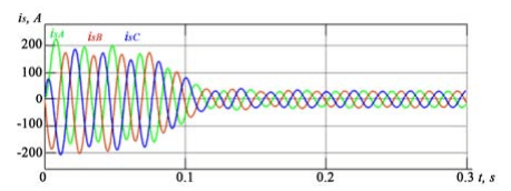
When setting symmetrical phase voltages of the stator on the model, the timing diagrams of which are shown in fig. 2, the values of the stator phase currents (fig. 3), the rotor phase currents (fig. 4) are obtained. The values of the stator phase voltage and the stator and rotor phase currents are given by the instantaneous values of these parameters.
Table 2. Calculation of the performance characteristics of an asynchronous motor


To evaluate the results of the selected mathematical model, simulation modeling of the electrodynamic processes of the operation of an asynchronous electric motor was carried out with the passport data given in Table 1. The results of modeling the dependence of active power (P1), useful power (P2) consumed from the network, average stator current (I1mid), efficiency (η), power factor (cosφ) and torque on the motor shaft (T) on the rotor speed (n2) are given in Table 3. The simulation modeling was carried out with a fixed speed of the motor shaft.
Table 3. Results of simulation modeling of an asynchronous electric motor operation

Useful power in table 3 is determined by:

where T – the moment on the motor shaft, N·m, ω – the rotation speed of the motor shaft.
The rotation speed of the motor shaft for pairs of field-owls p=2 is determined by:
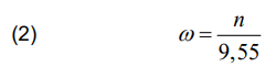
where n – the actual speed of the motor shaft, rpm.
The instantaneous reactive power is determined by:

Instantaneous apparent power consumed from the network:

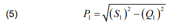
Then the value of the instantaneous active power consumed from the network can be determined as:
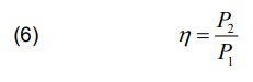
The efficiency is determined by:
The power factor can be determined using the expression:
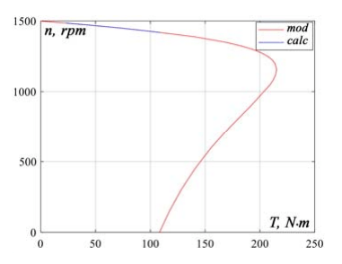
According to the results of simulation modeling (mod) given in Table 3 and calculated data (calc) from Table 2, the mechanical characteristics n2=f(T) and the dependence of the rotor speed on the useful load on the shaft n2=f(P2) are constructed in fig. 5 and fig. 6, respectively.

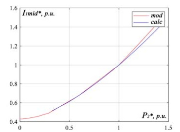
Based on the results of tables 3 and 2, the dependences are plotted for the relative value of the active power consumed from the network on the relative value of the useful power P1*=f(P2*) (P1/P1н=f(Р2/Р2н) (Fig. 7) and the dependence of the average relative value phase current of the stator on the relative value of useful power (I1mid*)=f(P2*) (I1/I1н)=f(Р2/Р2н) (Fig. 8).

Based on the results of tables 3 and 2, the dependences of the energy indicators of the motor are plotted: efficiency η =f(Р2/Р2н) (Fig. 9) and power factor cosφ=f(Р2/Р2н), (Fig. 10) on the relative value of the useful power.


Analysis of the results of simulation modeling in comparison with the calculated electrodynamic and energy characteristics and motor parameters shown in figures 5-10 indicates a high degree of compliance of the results obtained with the calculated ones and a sufficiently high dynamic stability of the model in the working range (T=23,0- 110,0 N·m) (see fig. 5, 6). The greatest deviations are the discrepancies in the energy indicators of the motor, which are 1,2% for the efficiency factor and 0,8% for the power factor cosφ, which is explained by the errors of the calculation method.
Conclusion
Defects or damage to squirrel-cage asynchronous motors require timely diagnosis and study of their effect on the parameters and characteristics of operating electrical equipment. An effective means of assessing the influence of defects on the energy and electrodynamic processes occurring in an asynchronous motor is simulation modeling. Verification and evaluation of results of simulation modeling obtained on specific mathematical models for compliance with real ongoing processes is a necessary issue that helps to increase the level of correctness of the results when they are used in further studies of asynchronous electric motors. The most reliable results on establishing the level of model adequacy can be obtained by conducting experimental studies on real objects. Taking into account the significant laboriousness of conducting experimental studies in the work, an approach is proposed for evaluating the results of simulation modeling by comparing them with a set of calculated energy and electrodynamic indicators of an asynchronous motor, which is the novelty of this work.
Based on the results of the studies, it is found that the greatest discrepancies between the calculated data and the data obtained during modeling take place for a set of energy indicators and are: for efficiency factor – 1,2%, for power factor cosφ – 0,8%, which is explained by errors calculation method. Comparison of the electrodynamic characteristics and parameters shows a fairly high accuracy of the results obtained in the simulation modeling. Thus, the discrepancies in the torque values at the nominal rotor speed n2 =1450 rpm are: the calculated value T=72,47 Nm, the value obtained by modeling T=72,443 Nm. The discrepancies in the values of the calculated and obtained by modeling torques over the entire operating range of the electric motor, with the rotation of the rotor shaft n2=1417- 1485 rpm, which corresponds to T=23,0–110,0 Nm, also have an insignificant level that can be neglected.
The research results have shown the possibility of using the proposed simulation model for further research, in particular, the impact on the manifestation of various types of electrical defects in an asynchronous motor on its performance, with a fairly high correspondence of the results to the calculated values.
Subsequent work will be aimed at studying the effect of interturn short circuit in the phases of the stator winding of an asynchronous electric motor on its performance using the proposed mathematical model while improving the system for diagnosing asynchronous motors.
REFERENCES
[1] Khechekhouche A., Cherif H., Menacer A., Chehaidia S.E., Panchal H. Experimental diagnosis of inter-turns stator fault and unbalanced voltage supply in induction motor using MCSA and DWER. Periodicals of Engineering and Natural Sciences (PEN), 2020, vol. 8, no. 3, pp. 1202-1216
[2] Ciprian H., Szabó L. Wavelet Analysis and Park’s Vector Based Condition Monitoring of Induction Machines. / H. Ciprian, L. Szabó // Juornal of Computer Science and Control Systems, vol. 4, no. 2, 2011, pp. 35-38
[3] Gubarevych О.V, Goolak S.О., Golubieva S.M. An integrated approach to diagnosing asynchronous electric motors of water transport. New technologies, 2019, no. 2(9), pp. 48-61
[4] Mairte J., Gaboury S., Bbouchard B., Bouzouane, A. A new computational method for stator faults recognition in induction machines based on hyper-volumes. In: 2015 IEEE International Conference on Electro/Information Technology (EIT). IEEE, 2015, pp. 216-220
[5] Culbert I., Letal J. Signature analysis for online motor diagnostics: Early detection of rotating machine problems prior to failure, IEEE Industry applications magazine, 2017, no. 23(4), pp. 76-81
[6] Liubarskyi B., Petrenko O., Shaida V., Maslii A. Analysis of optimal operating modes of the induction traction drives for establishing a control algorithm over a semiconductor transducer. Eastern-European Journal of Enterprise Technologies, 2017, vol. 4, no. 8 (88), pp. 65-72
[7] Lovska A., Fomin O.A New Fastener To Ensure The Reliability Of A Passenger Car Body On A Train Ferry. Acta Polytechnica, 2020, vol. 60, no. 6, pp. 478–485
[8] Shavelkin A.A., Gerlici J., Shvedchykova І.О., Kravchenko K., Kruhliak H.V. Management of power consumption in a photovoltaic system with a storage battery connected to the network with multi-zone electricity pricing to supply the local facility own needs. Electrical Engineering and Electromechanics, 2021, no. 2, pp. 36–42
[9] Shavolkin O., Shvedchykova I., Demishonkova S., Pavlenko V. Przeglad. Increasing the efficiency of hybrid photoelectric system equipped with a storage battery to meet the needs of local object with generation of electricity into grid. Elektrotechniczny, 2021, no. 97(11), pp. 144–149
[10] Eldeeb H.H., Berzoy A., Saad A.A., Mohammed O.A. On-line Monitoring of Stator Inter-Turn Failures in DTC driven Asynchronous Motors using Mathematical Morphological Gradient. In 2019 IEEE Applied Power Electronics Conference and Exposition (APEC), 2019, pp. 1018-1023
[11] Ayyappan G.S., Ramesh Babu B., Srinivas K., Raja Raghavan M., Poonthalir R. Mathematical Modelling and IoT Enabled Instrumentation for Simulation & Emulation of Induction Motor Faults. IETE Journal of Research, 2021, pp. 1-13. doi: 10.1080/03772063.2021.1875272
[12] Ali M.Z., Shabbir M.N.S.K., Liang X., Zhang Y., Hu T. Machine Learning-Based Fault Diagnosis for Single-and Multi-Faults in Induction Motors Using Measured Stator Currents and Vibration Signals. IEEE Transactions on Industry Applications, 2019, no. 55(3), pp. 2378-2391
[13] Goolak S., Gerlici J., Gubarevych O., Lack T., Pustovetov M. Imitation Modeling of an Inter-Turn Short Circuit of an Asynchronous Motor Stator Winding for Diagnostics of Auxiliary Electric Drives of Transport Infrastructure. Communications – Scientific Letters of the University of Zilina, vol. 23 no. 2, pp. 65-74. doi: 10.26552/com.C.2021.2. pp. 65-74
[14] Pustovetov M, Soltus К., Sinyavskiy I. Computer simulation of induction motors and transformers. Examples of interaction with power electronic converters. LAP LAMBERT. Academic Publishing, 2013
[15] Yu M., Zhu J., Qiang D., Zhu Y. Numerical calculation of global temperature field during phase failure of small induction motor. In 2019 Chinese Control Conference (CCC), 2019, pp. 7143-7148
[16] Singh A., Grant B., DeFour R., Sharma C., Bahadoorsingh S. A review of induction motor fault modeling. Electric Power Systems Research, 2016, no. 133, pp. 191-197
[17] Goolak S. Methodical recommendations for application of the model of physical processes in a three-phase asynchronous motor. Proceedings of the State University of Infrastructure and Technology. Series: Transportation Systems and Technologies, 018, no. 1(32), pp. 4-13
[18] Goolak S., Gerlici J., Sapronova S., Tkachenko V., Lack T., Kravchenko K. Determination of Parameters of Asynchronous Electric Machines with Asymmetrical Windings of Electric Locomotives. Communications-Scientific letters of the University of Zilina, 2019, no. 21(2), pp. 24-31
[19] Pustovetov M.Yu. Approach to Computer Implementation of Mathematical Model of 3-Phase Induction Motor. IOP Conf. Series: Materials Science and Engineering [online]. 2018, no. 327(2), 022085
[20] Goolak S., Gubarevych О., Yermolenko E, Slobodyanyuk M, Gorobchenko O. Development of mathematical model of induction motor for vehicles. Eastern-European Journal of Enterprise Technologies. 2020, no. 2/2 (104), pp.24-35
[21] Kopylov I.P. Designing of electrical machines. Textbook for high schools. M.: Yurayt, 2019. 828р
Authors: PhD, Associate Professor Oleg Gubarevych, State University of Infrastructure and Technologies, st. Kyrylivska 9, 04071, Kyiv, Ukraine, E-mail: oleg.gbr@ukr.net; Svitlana Golubieva, State University of Infrastructure and Technologies, st. Kyrylivska 9, 04071, Kyiv, Ukraine, E-mail: glbvvnu@gmail.com; PhD, Associate Professor Inna Melkonova, Volodymyr Dahl East Ukrainian Nationa University, Prospect Tsentralnyiy 59a, 93400, Severodonetsk, Ukraine, E-mail: melkonova@snu.edu.ua,
Source & Publisher Item Identifier: PRZEGLĄD ELEKTROTECHNICZNY, ISSN 0033-2097, R. 98 NR 10/2022. doi:10.15199/48.2022.10.11
