Published by Andrzej RAŹNIAK1, Magdalena DUDEK1, Tomasz SIWEK1, Piotr DUDEK2, Wojciech KALAWA1, AGH – Akademia Górniczo – Hutnicza im. Stanisława Staszica w Krakowie, Wydział Energetyki i Paliw (1) AGH – Akademia Górniczo – Hutnicza im. Stanisława Staszica w Krakowie, Wydział Inżynierii Mechanicznej i Robotyki (2)
Abstract: The possibilities of using low-temperature hydrogen-oxygen fuel cells with PEMFC proton-exchange membrane in transport and aviation were characterized and described. In this paper the emphasis was put on the investigation of energy efficiency of a commercial 5kW PEMFC fuel stack and on the possible directions to reduce the dimensions and weight of the PEMFC stack. Voltage dependencies were determined between voltage (U) -current (I) and current (I) – Power (P), as were the temperature distribution during the operation of the fuel cell stack and the peak current in humidifying the PEMFC stack by means of the SCU system. The energy demand of the 5kW fuel cell stack for the needs of the cooling system operation was determined (the so-called internal requirements of the fuel cell stack)
Streszczenie W pracy scharakteryzowano możliwości zastosowania niskotemperaturowych wodorowo-tlenowych ogniw paliwowych z protonowymienną membraną PEMFC w transporcie i lotnictwie. W pracy nacisk położono na zbadanie efektywności energetycznej komercyjnego stosu ogniw paliwowych PEMFC o mocy 5kW, a także możliwe kierunki zmniejszania jego masy i gabarytów. Wyznaczono zależności napięcie (U)– prąd (I) oraz prąd(I)-moc (P), rozkład temperatur podczas pracy stosu ogniw paliwowych, a także wielkości prądu w „piku” podczas nawilżania stosu PEMFC za pomocą układu SCU. Wyznaczono zapotrzebowanie energetyczne stosu ogniw paliwowych 5kW na potrzeby pracy układu chłodzenia (tzw. potrzeby własne stosu ogniw paliwowych) (Określenie parametrów elektrycznych oraz efektywności chłodzenia powietrznego niskotemperaturowego stosu ogniw paliwowych PEMFC o mocy 5kW)
Słowa kluczowe: ogniwa paliwowe z protonowymienną membraną PEMFC, chłodzenie powietrzne, wodór, efektywność energetyczna
Keywords: proton exchange membrane fuel cell PEMFC, air cooling, hydrogen, energy efficiency
Introduction
Among the five advanced types of hydrogen–oxygen fuel cells, the Polymer Membrane Fuel Cells (PEMFC) are more and more used in portable, stationary, and transport energy systems in different economic sectors. Nowadays, in Poland and worldwide, more and more attention is paid to the application of fuel cells (FC) in construction of power units for electric vehicles of a different type, unmanned aerial vehicles, aircrafts, means of the maritime and land transport, including submarines, inspection facilities for seabed, etc. [1-3]. According to the Fuel Cell Industry Review, in 2016, for the first time the total power of the fuel cells supplied for transport sector (280MW) was higher than the power of energy generators with fuel cells designated for stationary solutions (200MW). The main reason was the introduction of hydrogen-oxygen PEMFCs for construction of power units fueling the cars of Toyota Mirai in Japan, California and to a lesser extent in Europe [4]. The range of cars amounts to approx. 500-700 km, while the charge procedure for hydrogen containers takes approx. 5-6 minutes. PEMFCs are also increasingly used for construction of power units powering trucks, buses, and forklift trucks [5]. Generators with fuel cells (FC) with lower power, ranging from 100W to approx. 5 kW, are also used to power electric engines in scooters, bicycles, wheelchairs, unmanned ground robots [6,7]. An outstanding example is the “Burgman” scooter – the first motorcycle using hydrogen-oxygen fuel cells for power system. The motorcycle was designed by Suzuki, while PEMFC system is provided by Intelligent Energy. The motorcycle received the European type-approval as the first fuel cell vehicle in the world. Another interesting product is the hydrogenoxygen PEMFC bicycle developed by the consortium composed of the following companies: i) Cycleurope, manufacturer of electric bikes, ii) Ventec, manufacturer of energy management systems in electrochemical energy sources, iii) Pragma, manufacturer of PEMFC. Another innovative solution of this venture was the application of chemical source of hydrogen in the form of hydrogen-rich solid chemical compound. Hydrogen to power is produced on-line in reactor when riding a bike, and directly consumed by PEMFC [8,9].
Currently, in aviation it is aimed at reducing: consumption of non-renewable fuels, CO2 emissions and pollution, noise-reduction by using electric engines in power units and by using electrochemical energy sources to power the said engines. Hypothetically, three types of electrochemical sources (reservoirs) of the source of electrical power may be used in aviation electric drives: electrochemical batteries (EB), supercapacitors (SC) and fuel cells operated on hydrogen or alternative fuels. The most promising solution for construction of power systems is the application of fuel cells, which ensure the highest amount of energy generated by hydrogen-powered fuel cell stacks, stored under pressure in the composite, ultralight hydrogen container. With respect to fuel cells, electrochemical batteries, and even more supercapacitors, are characterized by unfavorable amounts of energy (amount of energy stored in the system with unit weight). However, their advantage is high power density (power generated/device weight). For this reason, it is necessary to consider the application of hybrid system with main fuel system in the form of fuel cells and energy reservoirs as EB or SC. It would support the main fuel system for starting, maneuvering or emergency purposes [10,11].
The application of PEMFCs in the technology of unmanned aerial vehicles (drones with airframe or rotary structures) causes the extension of flight time as compared to electrochemical batteries. The examples of models of UAV with hydrogen-oxygen fuel cells include: Helios (manufacturer of NASA), Antares DLR-H2 (Lange Aviation), Ion Tiger (U.S. Navy), Puma (AFRL, PTX, MCEL), Pterosoar (Horizon), HyFish (DLR, Germany), Mirador (DGA, France), Spider-Lion (AeroVironment, USA) or models by Georgia Inst of Technology (2006), KAIST (2007). The flight time for UAVs fuelled by gaseous hydrogen ranges from 0.2h to approx. 6h. It should be stressed that usually electrochemical energy sources used to power electric engines of UAV are built in the form of hybrid units: fuel cells cooperating with the battery [12,13]. PEMFCs have been successfully used to build power units with higher electric power. Powered sailplane Antares DRLH2, or Enfica-FC serves as good examples of the application of PEMFC in this industry [14,15]. In 2016 the German engineers from DRL carried out successful flight test of four-seater passenger aircraft HY4. During the 10-minute flight there were 2 pilots and 2 manikins on board the aircraft HY4. It uses hydrogen fuel cells enabling to achieve a cruising speed of 145 km/h and distance of 1500 km. The energy from the batteries is used during take-off and when landing [16].
Another important application area of fuel cells in aviation is Auxiliary Power Unit (APU). The fuel cells as auxiliary power units have already been successfully applied in large passenger aircrafts, such as Being, Airbus [17,18]. The advantage of APUs with fuel cells is the fact that they can operate independently, without main electric engines, and supply electricity during flight and ground operations for on-board infrastructure [19]. The FCs are also more and more used to fuel aviation ground support equipment (in English: Aviation ground support equipment – GSE). The article [20] presents the possibility of application of the PEMFC fuel cells stack with power of 5 kW to fuel mobile light tower at San Francisco International Airport, US. Other possibilities include the application of fuel cells for fueling buses transporting passengers or other aviation auxiliary vehicles [21].
However, despite the huge interest in fuel cells, the reference literature lacks systematic research regarding the energy efficiency of the PEMFC stacks. Target power generators, based on the PEMFC stacks, are equipped with many additional auxiliaries, which improve and support their proper operation. They include systems monitoring the humidification and dosage of gaseous reagents, cooling and temperature control system, hydrogen leakage detection sensors, start-up accessories and others.
Power generators with the PEMFC fuel cells in the scope of power ranging from 20 to 200 kW, dedicated for applications in land and air transport, are constructed on a modular basis. In order to construct the target generator, several units (fuel cell stacks) with lower electric power, electrically connected in serial or in parallel, are used to achieve the desired electrical parameters (such as voltage, current and electric power) tailored to the requirements of the fuelled electricity receivers. In the case of power modules from the FC with electric power of approx. 20- 50kW, these are usually the FC stacks with power of 5-10 kW [22]
The aim of this article is to determine characteristics of electrical parameters and energy efficiency of commercial PEMFC fuel cell stack 5kW as reference unit for construction of future power generators.
Experimental part
The subject of the research covers the gaseous hydrogen-fuelled low-temperature fuel cell stack with power of 5kW – H5000 (by Horizon, Singapore). The H5000 FC stack operates in the so-called “open-cathode” system (in English: open-cathode PEMFC stack). In this structure the elements of the PEMFC stack (single components of MEA and graphite bipolar plates) are arranged so that cathode areas to fuel with oxygen mainly from cooling air flow generated by the fan unit are available outside. The technical parameters of the PEMFC fuel cell stack selected for the research are included in the manufacturer’s specification [23]. Fig. 1 shows the photo of the PEMFC fuel cell stack H5000 (Horizon, Singapore). Fig. 1a shows the photo of the H5000 from the side of cooling fans. While Fig. 1b shows the photo of the H5000 PEMFC stack construction from the other side, i.e. air inlet to the cathode area.
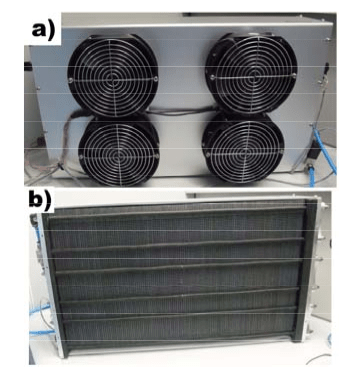
a) View from the side where 4 cooling fans were installed in the device
b) View from the side of the air inlet to the cathode area of the PEMFC stack
Apparatus and Method of Measurements
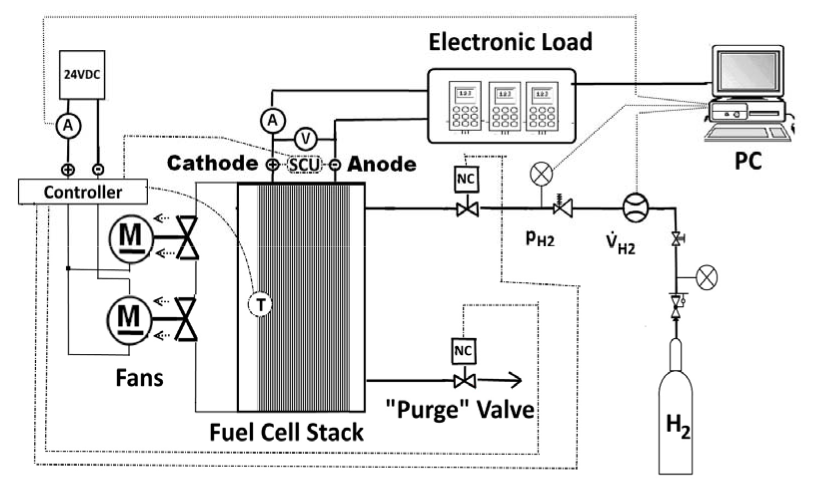
Fig. 2 shows the diagram of stationary setup for determining current (I) and voltage (U) characteristics of the tested H5000 PEMFC stack. The H5000 PEMFC stack was fuelled with hydrogen cylinder (Air Liquid ALPHAGAZ 1 H2 – purity 5.0). The dry gaseous hydrogen under pressure pH2=0.5bar +/-0.05 bar was supplied to the anode area of the H5000 PEMFC stack. The shut-off electronic valve NC (Normal Close) is mounted in the hydrogen supply valve. The operation of the electronic valve is regulated by the automatic control system of the operation of the FC stack. Directly at the outlet of unreacted hydrogen from the FC stack, the electronic valve NC “purge” is mounted, whose operation is controlled by the PEMFC stack controller. The “purge” electronic valve is used to periodically rinse the anode area of the fuel cell stack. The cooling system is a very important element of the tested PEMFC stack. In this solution it is a system of 4 fans, with power of 100 W each. The PEMFC stack operation controller is an integral component of the tested PEMFC stack. The PEMFC stack is humidified using the SCU (Short Circuit Unit) causing short periodical circuits of the PEMFC stack.
The H5000 PEMFC stack controller was powered from the external direct current power supply at voltage of 24VDC.
Methodology of Electrical and Thermal Measurements of the H5000 FC Stack
The characteristics of current (I) – voltage (U) and current (I) – power (P) were determined using the electronic load Chroma 63202 (2600W/0-50A/0-600V) enabling to load the stack up to the power of 2.5 kW. In order to increase the load of the tested H5000 PEMFC stack up to the volume exceeding nominal electric power of 5 kW, the electrical system was retrofitted with resistive loads. The volume of current (I) and voltage (U) from the PEMFC stack was measured using the multimeters. The value of current was measured on the shunt 150A/60mV using the Agilent 34411A multimeter, while the voltage U was measured using the Agilent 34410A multimeter. The use of transducers LEM 15 enabled to determine the current and electric power collected by the stack control system, predominantly for the purpose of cooling the H5000 stack. The data was archived by the measuring card LabJack U3- HV on the PC. During the electrical tests of the H5000 PEMFC stack with permanent or variable load, the temperature distribution along the entire length of the fuel cell stack was measured. The measurement of the FC stack temperature distribution field from the side of air inlet was carried out using the infrared thermal camera by NEC Thermo Tracer H2640 equipped with the bolometer infrared detector, resolution of 640×480 pixels, enabling the registration of temperature with a resolution of 0.03°C, and the emissivity value was at the level of e=0.95. The thermographs were analysed using the Thermography Studio Professional software.
Flow Tests and Characteristics of the H5000 FC Stack Cooling System
The analysis of air inflow speed distribution to inlet channels in bipolar plates in the H5000 FC stack was carried out using the combined, three-channel thermoanemometric sensor TURBULENCE METER type ATM 94 (Fig.3).
The used thermoanemometric sensor (Fig.3) enabling the measurement of the absolute speed and its components oriented in a classic, Cartesian coordinate system, is composed of three active elements in the form of tungsten fibres, 5μm thick and approx. 2mm long, spanning between the brackets. The brackets not only serve as mechanical attachment of fibre, but also electrical connection with the cable connector. Individual sensor fibres are placed so that they create the edge of the cube, whose axis overlaps with the sensor axis. The described sensor cooperated with the measuring card A/C PC LabCard PLC 814 installed on the PC, along with the measurement software developed by the Laboratory of Flow Metrology of the Strata Mechanics Research Institute of the Polish Academy of Sciences in Krakow. Before the use, the sensor was calibrated at the Calibration Laboratory for Ventilation Measuring Instruments of the Strata Mechanics Research Institute of the Polish Academy of Sciences in Krakow, holding the national accreditation confirmed by the certificate No. AP 118.

The flow characteristics of axial fans installed in the cooling system of the H5000 PEMFC stack were determined at the test stand prepared according to the standard PN-EN ISO 5801:2008. Test stand of the C type – measuring pipeline is installed on the suction side of the tested fan (6). The scheme of test stand is presented in Fig. 4

According to the numbering in Fig. 4 the louvre damper responsible for flow throttling (1) is installed at the inlet, the next element is the thermo-hygrometer model HD48T by Delta Ohm (2). In order to harmonize the speed profile, the stream straightener (3) is installed behind the damper. The measuring set composed of the airflow element by STRA Dwyer (4), averaging the dynamic pressure profile in the cable, and differential pressure transmitter by Halstrup Walcher P26 was used for airflow measurements. At a distance of 3 averages before the inlet to the rotor, the pressure signal at suction was introduced to the pressure gauge VPT-100 by Voltcraft. The tested fans (6) are powered from the laboratory power supply (8). The rotations were measured using the optoelectronic tachometer (7).
Research Results Characteristics of Performance Parameters of the H5000 PEMFC stack
The main factor determining the suitability of the PEMFC stack as the basic component for construction of power generators is the possible electric power for supplying to the power unit or other electricity receivers. Each galvanic cell, and thus the fuel cell stack, is characterized by maximum power points, to which the pair of parameters correspond (voltage-current)max. For certain types of galvanic cells, this point may not be visible on curve power (P) – current (I) (it often happens for primary cells), since its location is beyond the useful voltages or currents. In the case of fuel cell generators, the location of the point (voltage-current)max is usually clearly marked and plays an important role during the generator operation. When the fuel cell stack is being gradually loaded, it results in self-adjusting change of operating conditions (voltage drop, current increase, increase of hydrogen fuel consumption), which causes an appropriate increase of the power from the stack according to the growing demand. This mechanism will work effectively until it reaches the maximum power point, after exceeding this point, the power supplied by the cell stack will rapidly decrease, despite the increasing current load [24]. In the case of uneven demand for power in time, the often-used solution aiming at balancing the power is to use the assistance system in the form of peak batteries or supercapacitors [25, 26]
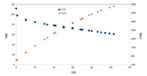
Fig. 5 shows the determined dependencies voltage (U) – current (I) and current (I) – power (P) for the tested H5000 FC stack in the scope of nominal power declared by the manufacturer..

Based on the presented in Fig. 5 dependencies between voltage (U) – current (I) and current (I) – power (P), it can be stated that for the tested PEMFC stack, the power of the PEMFC stack gradually increases up to the 5kW during the increase of current load. It is the value declared by the manufacturer as nominal power.
On the basis of this dependence, it may be concluded that the tested H5000 PEMFC stack has not achieved the power point Pmax yet, where after exceeding, there is usually the sharp decrease of electric power. In the initial part of the characteristics, voltage (U) – current (I) for the current ranging from 1 to approx. 10A, a significant voltage drop from the highest value of Uocv = 114V (OCV Open Circuit Voltage) to the value of U = 85V can be observed. This fact is related to activation losses dominant within this scope of the FC operation. Within the research scope of the applied electric loads, the power of the H5000 device does not exceed 1kW, and the operating temperature approximates the ambient temperature (20oC).
Further increase of electrical load of the H5000 PEMFC stack with current of 10A-70A causes a linear voltage drop resulting from ohm losses dominant within this part of characteristics of U=f(I). The nominal power point of 5kW declared by the manufacturer of the FC stack corresponds to the pair of U = 72V, I = 70A. The received results are compliant with the nominal electrical parameters of the H5000 PEMFC stack declared by the manufacturer [23].
However, for stationary, transport or aviation applications of the fuel cells for construction of power generators, the important factor is the information whether or not it is possible to increase power in case of intermittent demand by the power unit [27,28].
Fig.6 shows another dependence between voltage (U)- current (I) and power (P)-current (I) under expanded range of electrical load, i.e. above the nominal power of 5kW.
As it follows from the determined dependencies (Fig. 6) between voltage (U) – current (I) and power (P) – current (I), the H5000 fuel cell stack achieved the power of approx. 6 kW. Similarly to the previous dependencies (Fig. 5), the tested generator also failed to achieve the maximum power point Pmax. These results confirm that the declared and achieved power value of 5kW, by the tested power source, is not the highest peak value for this device. The tested H5000 FC stack has some power reserve. Due to the durability of the PEMFC and repetitive performance parameters of the tested stack, the team determined the critical power value not higher than 6kW.
Apart from electricity, the waste heat and water are the output of the PEMFC stack. In practice, the efficiency of the PEMFC stacks amounts to approx. 50%. Thus, in the case of the tested device, in addition to electricity of 5 kW, also the heat of 5 kW was received, which must be removed from fuel cells in this H5000 PEMFC stack. The most commonly used methods of waste heat collection include: a) air cooling using fans, b) cooling using the liquid medium, c) cooling using the passive elements [29-31].
The selection of cooling technology depends on the volume of the power generated by the PEMFC stack, its application (portable, stationary) as well as structure of bipolar plates combining the PEMFCs in the stack. The problem of cooling the PEMFC stack is a complex issue having a very large impact on the energy efficiency of the device. Too low efficiency of the cooling system may cause local and rapid increase of temperature along the entire length of the FC stack, and thus, may cause rapid loss of humidity by nafion polymer membrane, and in extreme cases, may result in thermal damage to a single MEA (in English: Membrane Electrode Assembly; MEA, name refers to a single PEM fuel cell). The occurrence of temperature gradient in the FC stack may also generate thermomechanical stresses in bipolar plates causing their gradual degradation [32].
On the other hand, too high cooling air flow rate causes: a) excessive removal of humidity from cathode area, which may result in drying of MEA and increase of internal resistance of the FC, and b) supercooling, which prevents the achievement of optimal operating temperature by the FC stack, decreasing the electrochemical reaction time, resulting in the decrease of efficiency of the whole FC. Thus, the cooling system is an integral element of power generator with the PEMFC. This fact makes it necessary to determine the energy consumption by the FC stack for powering and controlling the cooling system, in other words, for the so-called FC stack own purposes. This factor determines the need to select flow machines (fans) operating under optimized conditions, i.e. with high efficiency. The authors determined the demand for electricity for powering axial cooling fans installed on commercial H5000 FC stack. It should be stressed that cooling fans are responsible for main consumption of electricity (the so-called own purposes) of the fuel cell stack during operation.
Fig. 7 shows the dependence of variation in electric power Nel necessary to produce air flow by the cooling fan. The tests were performed for various supply voltages ranging from 8 to 24 V.

As it follows from Fig. 7, the highest electric power consumption Nel amounting to approx. 100 W, at a voltage of 24V was registered for the air flow ranging from 0.02 to 0.07 m3/s, while the increase of the cooling air flow produced by the fan causes insignificant decrease of the consumed power Nel to the level of approx. 70-80 W. Similar dependencies can be observed for lower supply voltages. The decreased demand for electric power Nel for powering the fan, along with the increase of air flow, is caused by lower increase of total pressure ∆p and an increase of efficiency, which is presented in Fig. 8 and 9. Fig. 8 illustrates the dependence of total pressure increase ∆p on air flow. The tests were performed for supply voltages ranging from 8 to 24 V
Fig. 8 presents the characteristics of increase of ∆p in efficiency function for different supply voltages of the fan motor. These characteristics compared to the characteristics of pressure losses in the FC stack are used to determine the fan operation point. Optimally, these points should fall within the areas of the highest efficiency of fans. Fig. 9 shows the determined dependence of electrical efficiency of a single axial fan in the function of air flow. By analysing the diagrams from Fig. 8 and Fig. 9 as well as flow characteristics of the PEMFC stack (pressure losses), the air distribution control algorithm, which is optimal in terms of energy, can be determined, which leads to the minimization of the cell own purposes


Based on the presented flow characteristics of the fan, it can be stated that the cooling system composed of 4 fans, is characterized by moderate efficiency. For optimized operating conditions for a single device, it amounts to approx. 40-45% depending on the supply conditions. The air flow produced by axial fans through cathode channels in bipolar plates is mainly used to cool the FC stack, but it is also used to fuel the cathode of individual cells in the FC stack with oxygen. There are 120 single MEA units in the H5000 FC stack. Fig. 10 shows the dependence of the air inflow speed to the FC stack on the electric power consumed by the 4 axial fans cooling FC.

As it follows from Fig. 10, the air inflow speed to the cathode areas of the FC stack, as expected, depends on the power consumed by the system of 4 fans and does not depend whether or not the air inflow speed to the PEMFC increases or decreases during the measurements. This fact is particularly important in dynamically changing conditions of the power generator operation with the FC, where it will be necessary to dose the same amount of air in order to maintain the performance parameter repetitiveness.
Another proper operation test of the cooling system was the analysis of homogeneity of air flow speed distribution to the cathode areas in the FC stack.
The flow qualitative test (comparison of the air inflow distribution) using the thermoanemometric probe was carried out within ¼ of the air inflow area to the H5000 FC stack. During the tests, the axial symmetry of flow phenomena in the tested H5000 device was assumed. Fig. 11 presents the photograph of the H5000 PEMFC stack with distribution of measuring series.
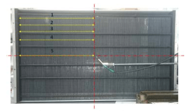
In turn, Fig. 12 presents the determined changes in air inflow speed to the H5000 fuel cell stack according to the adopted measuring series. For the distance, the value “0” was assumed on the edge of the FC stack.

Based on the conducted measurements, it is stated that there is the differentiation of air inflow speed supplied by the fans of the PF stack. The air is supplied at different speed to individual single PEMFC in the FC stack. However, on the basis of electrical characteristics, a negative impact of this phenomenon is not stated in the case of free position of the device on stationary stand. If the device is installed in electric vehicle or aircraft airframe, this factor may have an impact limiting the FC stack to achieve the highest electrical parameters.
During the operation of the FC stack with variable electrical load, in addition to electricity, also heat is generated on the internal resistance of the FC as a result of electrical current flow. In order to keep the optimal operating temperature below 65oC in the FC stack, it is cooled by means of the forced (by 4 fans) cooling air flow through cathode channels in bipolar plates. The temperature change distribution on the surface of the FC stack from the side of air inflow to cathode channels during the operation was recorded using the thermographic camera Fig.13 a-b.
Fig. 13b shows the temperature distribution profile on line 1 (Fig. 13 a) over the entire width of the FC stack during the maximum electrical load of the stack during the measurements. The even temperature distribution with slight increase of temperature of 2-4K at the ends of the FC stack can be observed both on the thermograph (Fig. 13a) and on line 1 (Fig. 13 b). It probably follows from minor unevenness of cooling air flow through cathode channels caused by 4 axial cooling fans positioned on the opposite side of the FC stack.

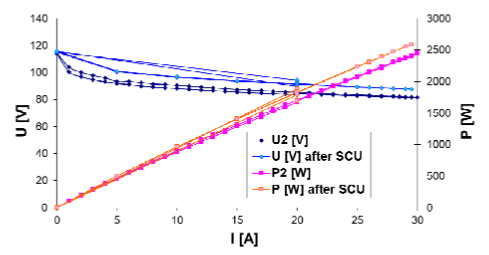
An important issue also pertains to the analysis of humidification level of each 120 single PEMFC membrane in the H5000 FC stack. During the operation of the FC stack with current load, a crucial issue is the control of polymer membrane humidification level, so that its internal resistance is not increased due to the excessive drying. The H5000 FC stack can be humidified by retrofitting the reagent dosing system in membrane humidification devices. This solution is the most frequently applied for the FC stacks constructed in the so-called closed cathode system. On the other hand, in the case of the tested structure of the FC stack, with the so-called open cathode, a special SCU (Short Circuit Unit) is used for self-humidification of polymer membranes of the FC stack. As a result of short circuits of the FC due to electrochemical reaction, there is the excess water resulted from the increased flow of short-circuit current, which humidifies polymer membranes. A positive impact of the SCU on the H5000 stack performance parameters is presented in Fig. 14, where the compared characteristics voltage (U) – current (I) and power (P) – current (I) with the SCU switched on or off are presented.
Based on the recorded characteristics of voltage (U) – current (I) and power (P) – current (I) for the FC stack, with the SCU switched on or off respectively, it may be concluded that the fact that the SCU was switched on, it caused the improvement of both value of voltage and power generated by the FC stack. This fact is directly connected with the drop of its internal resistance as a result of humidification of the PEMFC membrane.
One of the factors guaranteeing the continuity of humidification of the PEMFC membrane in the fuel cell stack by means of the SCU is the control of the SCU switching frequency. For the functioning of the control system of the FC stack performance parameters and other components of the power system, it is important to know the value of short-circuit current during switching on the SCU and the FC stack voltage reaction during and after the short circuit.
The knowledge of the above, fast-changing and short-term changes of current and voltage during the SCU short circuits should facilitate the selection of protective and receiving devices cooperating with the fuel cell stack, such as voltage converter, or necessity to retrofit the power system in supercapacitor.
For this purpose, during the short circuit caused by the SCU, the voltage drop at the output of the H5000 FC stack (comprising 120 fuel cells) as well as short-circuit current on the shunt 1000A/100mV were measured using the 2- channel oscilloscope RIGOL DS1062CA.
Fig. 15 shows a single SCU short circuit at load current of 36A, the duration of which amounts to approx. 55ms (curve 1 – short-circuit current measured on the shunt) and the corresponding cell voltage reaction (curve 2 – voltage on the fuel cell stack, multiplier x10).

Based on the performed weight analysis of individual components of the H5000 device, it is concluded that total weight of fans amounts to 3.3 kg, and the FC controller weight with electric cables amounts to approx. 3 kg. It should be stressed that the exchange of fans into the unit with higher efficiency and less weight when designing the device for portable solutions is not the serious problem for the present solutions in the technology. Another action aiming at reducing the FC stack weight is the exchange of casing made of aluminium (weight of approx. 6 kg) with the casing made of composite coat material or other plastic. The greatest technological problem is to replace bipolar graphite plates (estimated weight of 121 bipolar plates amounts to approx. 9kg, and the thickness of a single plate hc amounts to 4mm, i.e. 121 plates in the H5000 FC stack amounts to 48 cm, components MEA 12 cm, each of 120 has 1mm), and the length of the whole H5000 FC stack with the casing amounts to approx. 65 cm. On the basis of the analysis of reference literature, it can be stated that the application of metal bipolar plates could enable reduction of the weight to approx. 4 kg, and reduction of the length of the whole FC stack by at least 30%.

Summary
This article presents the research results of energy efficiency of the H5000 PEM fuel cell stack, which is air-cooled. The basic electrical parameters of the H5000 FC stack are determined in order to not only define the nominal power of the H5000 stack, but also to define the possibility to increase such power as a result of sharp increase in demand for electric power of the receiver. The characteristic parameters of the cooling system composed of 4 cooling fans are also determined. As it follows from the presented research, the energy efficiency of the applied fans ranges from 40 to 45%. A moderate efficiency of the FC cooling unit may be the reason for the increase of the fuel cell generator’s own purposes. The next analysed parameter was the speed distribution of air inflow to cathode openings in bipolar plates of the FC stack. Based on the presented research, the heterogeneous air inflow is determined, which does not materially affect the electrical parameters of the FC stack operating on a stationary stand in the ambient air cooling conditions. The PEMFC stacks for structures, in which metal bipolar plates enabling the reduction of weight and size are applied, will be the future solution for portable applications.
Acknowledgments The research presented in this paper was financed as a project PBS3/A6/24/2015 AOS-H2 the Applied Research Programme (PBS) of the National Centre for Research and Development (NCBIR), Poland, in the years 2015–18. Some of the measurements were performed using the research infrastructure of the AGH Centre of Energy.
REFERENCES
[1] Garche J, Encylopedia of Electrochemical Power Sources Elsevier 2009
[2] Wu H, A review of recent development: Transport and performance modelling of PEM fuel cells, Applied Energy, 1 (2016) 81-106
[3] Broussely M, Pistoia G, Industrial Application of Batteries. From Cars to Aerospace and Energy Storage, Elsevier, Amsterdam, 2007
[4] The Fuel Cell Industry Review 2016 http://www.fuelcellindustryreview.com (15.07.2017)
[5] Miranda P.E, Carreira E.S., Icardi U.A., Nunes G.S.Brazilian hybrid electric-hydrogen fuel cell bus: Improved on-board energy management system, International Journal of Hydrogen Energy, 42 (2017) 13949-13959
[6] Mellino S, Petrillo A, Cigolotti V, Autorino C, Ulgiati S, A Life Cycle Assessment of lithium battery and hydrogen-FC powered electric bicycles: Searching for cleaner solutions to urban mobility, International Journal of Hydrogen Energy, 42, (2017), 1830-1840
[7] Rajashekara K, Hybrid and fuel cell system for transportation, Electrical Review, 80 (2004) 1033-1039
[8] London police trialing Suzuki scooters with Intelligent Energy units, Fuel Cell Bulletin, 9 (2017) 3-4
[9] French group launch fuel cell powered bike to boost emobility, Fuel Cell Bulletin, 7 (2013) 3-4
[10] Pratt J., Klebanoff L., Ramos K., Akhil A. A., Curgus D.B., Shenkman B.L., Proton exchange membrane fuel cells for electrical power generation on-board commercial airplanes, Applied Energy 101 (2013) 776-796
[11] Bicer Y, Dincer I, Life cycle evaluation of hydrogen and other potential fuels for aircrafts, International Journal of Hydrogen Energy, 42 (2017) 10722-10738
[12] Donateo T., Ficarella A., Spedicato L., Arista A., Ferraro M. A new approach to calculating endurance in electric flight and comparing fuel cells and batteries, Applied Energy 187 (2017) 807–819
[13] MMC next-gen fuel cell powered drone with telecom upgrade Fuel Cells Bulletin, 3 (2017) 5
[14] Intelligent Energy fuel cells significantly boost drone flight time, Fuel Cells Bulletin, 1 (2016) 4
[15] Fuel cells power first take off for DLR’s Antares aircraft, Fuel Cell Bulletin, 9 (2009) 3
[16] Romeo G., Borello F., Correa G., Cestino E., ENFICA-FC: Design of transport aircraft powered by fuel cell & flight test of zero emission 2-seater aircraft powered by fuel cells fueled by hydrogen, International Journal of Hydrogen Energy, 38 (2013) 469-479
[17] HySA Systems, SA National Aerospace Centre, Airbus study fuel cells for commercial airliners, Fuel Cell Bulletin, 9 (2014) 1
[18] Boeing fuel cell plane in manned aviation first, Fuel Cell Bulletin, 4 (2008) 1
[19] Sharaf O.Z., Orhan M.F., An overwiew of fuel cell technology: Fundamentals and application, Rewenable and Sustainable Energy Reviews, 32 (2014) 810-853
[20] Multiquip launches lighting tower powered by Altergy fuel cell, Fuel Cells Bulletin, 2 (2011) 5
[21] Plug Power, FedEx project rolls out fuel cell airport tractors, Fuel Cells Bulletin, 5 (2015) 2-3
[22] Fontela A., Soria A., Mielgo J., Sierra J.F., Blas J., Gauchina L., Martinez M., Airport electric vehicle powered by fuel cell, Journal of Power Sources, 10 (2007) 184-193
[23] https://www.horizonfuelcell.com/h-series-stacks (11.10.2017)
[24] Dudek M., Celowski P., Lis B., Raźniak A., Dudek P., Laboratoryjny generator energii elektrycznej o mocy 360W zawierający niskotemperaturowy stos ogniw paliwowych PEMFC chłodzony za pomocą medium ciekłego, Electrical Review, 92 (2016) 235–242
[25] Lü X., Miao X., Liu W., Lü J., Extension control strategy of a single converter for hybrid PEMFC/battery power source, Applied Thermal Engineering, 128 (2018) 887-897
[26] Lopez G.L., Rodriguez R.S., Alvarado V.M., Gomez-Aguilar J.F., Mota J.E., Snadoval C., Hybrid PEMFC-supercapacitor system: Modeling and energy management in energetic macroscopic representation, Applied Energy, 205 (2017) 1478-1494
[27] Sami B.S, Sihem N., Zafar B., Adnane Ch., Performance study and efficiency improvement of Hybrid Electric System dedicated to transport application, International Journal of Hydrogen Energy, 27 (2017) 12777-12789
[28] Saadi A., Becherif M., Hissel D., Ramadan H.S., Dynamic modeling and experimental analysis of PEMFCs: A comparative study, International Hydrogen Energy, 42 (2017) 1544-1557
[29] Chen, Y.Ch., Huang K.P., Yan W.M., Lai M.P., Yang C.C., Development and performance diagnosis of a high power aircooled PEMFC stack, International Journal of Hydrogen Energy, 41 (2016) 11784-11793
[30] Fly A., Thirng R., A comparison of evaporative and liquid cooling methods for fuel cell vehicles, International Journal of Hydrogen Energy, 41 (2016) 14217-14229
[31] Özden E., Tolj I., Barbir F., Designing heat exchanger with spatially variable surface area for passive cooling of PEM fuel cell, Applied Thermal Engineering, 51(2013) 1339-1344
[32] Zhang G., Kandlikar S.G., A critical review of cooling techniques in proton exchange membrane fuel cell stacks, International Journal of Hydrogen Energy, 37 (2012) 2412-2429
Authors: dr hab. inż. Magdalena Dudek AGH Akademia Górniczo – Hutnicza im. Stanisława Staszica w Krakowie, Wydział Energetyki i Paliw , al. A. Mickiewicza 30, 30-059 Kraków, E-mail: potoczek@agh.edu,pl; dr inż. Piotr Dudek, AGH-Akademia Górniczo – Hutnicza im. Stanisława Staszica w Krakowie, Wydział Inżynierii Mechanicznej i Robotyki, al. A. Mickiewicza 30, 30-059 Kraków, E-mial: pdudek@agh.edu.pl; mgr inż. Wojciech Kalawa, AGH Akademia Górniczo – Hutnicza im. Stanisława Staszica w Krakowie, Wydział Energetyki i Paliw, al. A. Mickiewicza 30, 30-059 Kraków e-mail: kalawa@agh.edu.pl; dr inż. Andrzej Raźniak AGH- Akademia Górniczo – Hutnicza im. Stanisława Staszica w Krakowie, Wydział Energetyki i Paliw, al. A. Mickiewicza 30, 30-059 Kraków, E-mial: razniak@agh.edu.pl; dr inż. Tomasz Siwek, AGHAkademia Górniczo-Hutnicza im. Stanisława Staszica w Krakowie, Wydział Energetyki i Paliw, al. Mickiewicza 30, 30-059 Kraków, Emial: siwek@agh.edu.pl;
Source & Publisher Item Identifier: PRZEGLĄD ELEKTROTECHNICZNY, ISSN 0033-2097, R. 94 NR 4/2018. doi:10.15199/48.2018.04.34
