Published by Andrzej POPENDA, Czestochowa University of Technology
Abstract. In the paper the uncomplicated structure of the active limiter of current reference for a BLDC motor control system is proposed. The limiter allows for uninterruptible operation of a speed controller due to the automatically adjusted rate of change of angular velocity reference depending on actual moment of inertia. The results of investigations, which confirm the effectiveness of the proposed structure, are presented.
Streszczenie. W artykule zaproponowano nieskomplikowaną strukturę aktywnego ogranicznika prądu zadanego w układzie regulacji prędkości kątowej silnika BLDC, która umożliwia bezprzerwowe działanie regulatora prędkości dzięki automatycznemu dostosowaniu szybkości narastania prędkości zadanej do dowolnego momentu bezwładności. Zaprezentowano wyniki badań, które potwierdzają skuteczność działania proponowanej struktury. (Tłumienie drgań w elektrycznym układzie napędowym z długim elementem sprężystym).
Keywords: electric drive system, speed controller, transmission shaft, vibration.
Słowa kluczowe: elektryczny układ napędowy, regulator prędkości, wał transmisyjny, drgania.
Introduction
Rapid development and diversity of electric drive systems require extensive theoretical and practical knowledge as well as the use of a wide range of theoretical and constructional solutions from the contemporary designers and users. Electric drive systems are used in all branches of industry, therefore, the trouble-free operation of these systems is of crucial importance. An analysis of the states of electric drive operation is often related to ensuring its safety. A key issue is to detect the mechanical resonance phenomenon or the phenomena close to resonance as the most unsafe ones for the system. Ignoring the analysis and the ongoing diagnostics of vibrations in electromechanical systems results in many failures [1, 2].
Electric motor, being a part of an electric drive, is coupled with a working mechanism via a driving shaft that is an element of mechanical power transmission. Mechanical power transmissions can be single-path or multi-path and can also include gear trains and clutches [3, 4]. The long driving shafts, defined as transmission shafts, are used first of all in the drive systems for the steel industry, mainly in the drive systems for rolling mills – the transmission shafts are over 10 meters long and their diameters are of 0.5 to 0.8 m [1-8]. Transmission shafts are also used in drive systems for polymerization reactors [5]. The length of these shafts is from 4 to 7 meters. Moreover, transmission shafts are used in hydro generator sets, ship drive systems, submarine drive systems, etc. [1].
Control systems for electric motors are usually equipped with the controllers of position, speed and current or torque, e.g. [10]. Step change or rapid change of angular velocity reference result in the temporary lock-down of the speed controller as a consequence of the applied limiter on the controller output (current reference limiter). Particularly negative consequences of such lock-down can be observed in drive systems, in which there are long elastic couplings (transmission shafts) between an electric motor and a working machine. As a consequence, transmission shafts are being twisted and moments of torsion of significant magnitude occur. The amplitude of these moments can be much higher than the rated torque of motor.
In the paper the uncomplicated structure of the active limiter of current reference for a brushless dc (BLDC) motor control system is proposed. The limiter allows for uninterruptible operation of speed controller due to the automatically adjusted rate of change of angular velocity reference depending on actual moment of inertia.
The electric drive system with a long elastic coupling
The investigated drive system includes the BLDC motor of 4 kW with a control system, steel transmission shaft of length 0.66 m and diameter 0.008 m, the additional rotating mass with moment of inertia JL and dc generator (Fig. 1) [1, 2]. Two rotary incremental encoders with a resolution of 3600 pulse/rev, installed on the transmission shaft ends, are used to measure angular displacement and angular velocity. Hall effect transducers were used to measure motor phase currents. The measuring signals from the transducers are sent to a laboratory computer equipped with two multifunctional I / O devices.
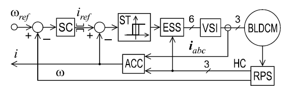
In Fig. 2 the block diagram of a standard structure of BLDC motor (BLDCM) control system is shown. Closed-loop controllers of rotor angular velocity and armature current are included in the system, e.g. [9]. Similar solutions are used to control both brushless and brushed dc motors, but the armature current of brushed dc motor is obtained as a result of a direct measurement. It should be noted that also control systems for ac motors include speed controllers and current controllers or alternatively torque controllers, e.g. [11].
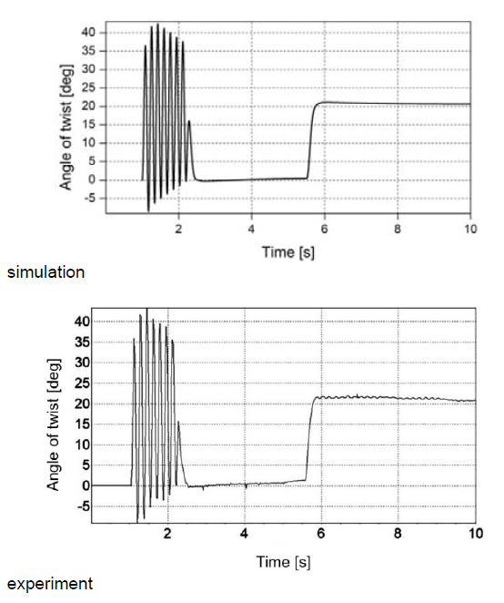
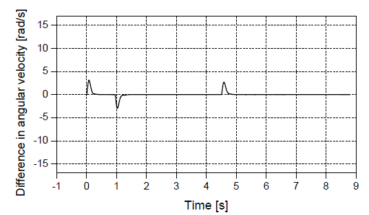
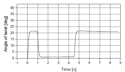
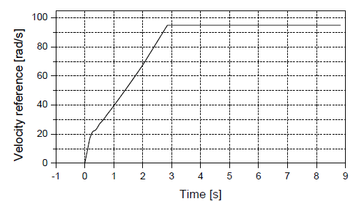
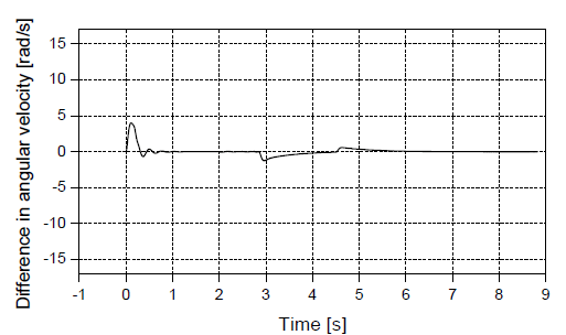
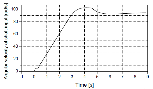
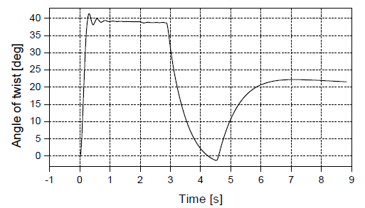
In Figs. 3 to 6 the exemplary waves of angular velocities at shat input and output, difference in angular velocity and angle of shaft twist for the investigated drive system during starting a motor, an idle run and a run under load, respectively, are shown [1]. The waves were obtained by using both computer simulation and measurements on the test stand (Fig. 2). The long driveshaft modelling algorithm based on an electric transmission line [1] was used in the simulation.


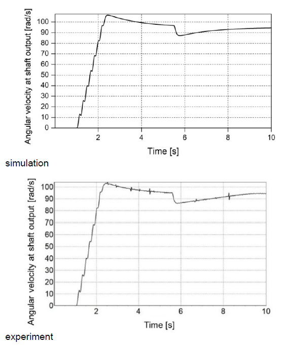

The parameters of 4 kW BLDC motor and steel transmission shaft of length 0.66 m and diameter 0.008 m, according to the real laboratory setup elements [1], were taken into simulation. The end of the transmission shaft was loaded by a rotating mass JL = 0.11 kg·m2 and a mechanical torque of rated value.
A lock-down of speed controller is clearly visible within the first second of starting a motor i.e. from the instant when a step change of motor angular velocity reference occurs at the system input (Figs. 3 to 6). However, as far as the speed controller exits from the limiter zone, the vibrations are damped quickly as a consequence of unlocking the speed controller operation. In addition, a standard control system (Fig. 2) reduces vibrations effectively without the additional damping circuits or devices.
The active limiter of current reference for a BLDC motor control system
The solution for vibration damping at each operational state of drive system, also during starting a motor, is a slowdown of the angular velocity reference rate of rise. However, the intensity of such slowdown should correspond with actual moment of inertia of motor rotor and rotating masses connected to it. In more complex working mechanisms this task requires determination of an equivalent moment of inertia expressed in motor shaft terms. Instead, this paper proposes the uncomplicated structure of the active limiter of current reference (Fig. 7) which allows for uninterruptible operation of speed controller due to the automatically adjusted rate of change of angular velocity reference depending on actual moment of inertia. This structure may be connected to the standard BLDC motor control system (Fig. 2).

In Figs. 8 to 19 the exemplary waves of angular velocity reference, difference in angular velocity, angular velocities at shat input and output, electromagnetic torque of motor and angle of shaft twist in the investigated drive system equipped with the proposed active limiter of current reference (Fig. 7) are shown.


The same operational conditions were taken into account like for the described previously system with a static current limiter (Fig. 2) i.e. starting a motor, an idle run and a run under load, respectively. The end of the transmission shaft was loaded by an additional rotating mass JL = 0.11 kg·m2 and 0.94 kg·m2, respectively, and a mechanical torque of rated value.
Conclusions
In the paper the uncomplicated structure of the active limiter of current reference for a brushless dc (BLDC) motor control system is proposed. The limiter allows for uninterruptible operation of speed controller due to the automatically adjusted rate of change of angular velocity reference depending on actual moment of inertia. The proposed solution allows for damping of vibration at each operational state of drive system i.e. during starting a motor, an idle run and a run under load, etc. This is particularly important in drive systems, in which there are long elastic couplings (transmission shafts) leading to the significant level of vibration in mechanical system.
REFERENCES
[1] Popenda A. , Lis M., Nowak M., Blecharz K., Mathematical Modelling of Drive System with an Elastic Coupling Based on Formal Analogy between the Transmission Shaft and the Electric Transmission Line, Energies, 1181(2020), No. 13, 1-14
[2] Lis M. , Modelowanie matematyczne procesów nieustalonych w elektrycznych układach napędowych o złożonej transmisji ruchu, Wydawnictwo Politechniki Częstochowskiej, Częstochowa 2013
[3] Popenda A., Mathematical modelling of transmission shafts based on electrical and mechanical similarities, Przegląd Elektrotechniczny, 95(2019), No. 12, 196-199.
[4] Rusek A., Stany dynamiczne układów napędowych z silnikami indukcyjnymi specjalnego wykonania, Wydawnictwo Politechniki Częstochowskiej, Częstochowa 2012
[5] Popenda A., Modelowanie i symulacja dynamicznych stanów pracy układów napędowych do reaktorów polimeryzacji z silnikami indukcyjnymi specjalnego wykonania, Wydawnictwo Politechniki Częstochowskiej, Częstochowa 2011
[6] Czaban A. , Lis M. , Mathematical Modelling of Transient States in a Drive System with a Long Elastic Element, Przegląd Elektrotechniczny, 88(2012), No. 12b, 167–170.
[7] Lis M. , Szaf raniec A. , Model matematyczny synchronicznego układu pompowego o podatnej transmisji ruchu, Maszyny Elektryczne – Zeszyty Problemowe, 118(2018), nr 2, 165–170.
[8] Szaf raniec A. , Modelowanie matematyczne procesów oscylacyjnych w napędzie elektrohydraulicznym o podatnej transmisji ruchu, Przegląd Elektrotechniczny, 93(2017), nr 12, 167-170
[9] Andr zejewski A. , Time-Optimal Position Control of DC Motor Servo Drive, Przegląd Elektrotechniczny, 95(2019), No. 12, 85-88
[10] Jakubiec B. , Napęd bezszczotkowego silnika prądu stałego z rozmytym regulatorem prędkości, Przegląd Elektrotechniczny, 90(2014), No. 12, 211-213
[11] Olesiak K. , Application of a fuzzy logic controller for a permanent magnet synchronous machine drive, Przegląd Elektrotechniczny, 92(2016) No. 12
Author: dr hab. inż. Andrzej Popenda, profesor uczelni, Politechnika Częstochowska, Wydział Elektryczny, Katedra Elektroenergetyki, al. Armii Krajowej 17, 42-200 Częstochowa, E-mail: andrzej.popenda@pcz.pl.
Source & Publisher Item Identifier: PRZEGLĄD ELEKTROTECHNICZNY, ISSN 0033-2097, R. 97 NR 12/2020. doi:10.15199/48.2020.12.49
