Published by Justyna HERLENDER, Jan IŻYKOWSKI, Eugeniusz ROSOŁOWSKI, Wroclaw University of Science and Technology, Department of Electrical Power Engineering
Abstract. This paper deals with analysis of impedance-differential protection applied to locating faults on power transmission line. Based on the voltage and current measurements at both line ends, the differential impedance is calculated. It enables to formulate efficient protective algorithm. Moreover, the presented impedance-differential protection has ability to determine the fault location for an inspection-repair purpose. The fault signals from ATP-EMTP simulations of faults on the sample transmission line was applied for evaluating the fault location accuracy and to compare with the other fault location methods.
Streszczenie. Artykuł prezentuje analizę impedancyjnego zabezpieczenia różnicowego w zastosowaniu do lokalizacji zwarć w linii przesyłowej. Stosując pomiary napięć i prądów na obu końcach linii wyznaczana jest impedancja różnicowa. Pozwala ona na sformułowanie efektywnego algorytmu zabezpieczeniowego. Ponadto takie zabezpieczenie pozwala na lokalizowanie zwarć do celów inspekcyjno-remontowych. Sygnały zwarciowe z symulacji zwarć w przykładowej linii przesyłowej z użyciem programu ATP-EMTP zastosowano do oceny dokładności lokalizacji i porównania z innymi metodami lokalizacji (Impedancyjne zabezpieczenie różnicowe jako lokalizator zwarć w linii przesyłowej).
Keywords: impedance-differential protection, transmission line, fault location, fault simulation.
Słowa kluczowe: impedancyjne zabezpieczenie różnicowe, linia przesyłowa, lokalizacja zwarć, symulacja zwarć.
Introduction
Published fault statistics [1]-[2] unambiguously indicate that majority of total number of power system faults occur on overhead power lines. Such faults have to be detected and then located by protective relays as well as by fault locators [2]. In order to prevent spreading out the fault effects, the identified fault has to be cleared by a circuit breaker tripped by a protective relay as quickly as possible. Improvement of protective relays operation is of concern in many researches performed all over the world. Application of synchronized measurements [3]-[5] appears as one of the means for that purpose. In particular, such measurements allow to get modern differential protection systems of overhead power transmission lines [6]-[8].
This paper deals with impedance-differential relay providing effective protection of transmission lines [7]. The traditional current differential relays [6] apply measurements of three-phase currents at the line ends, while the impedance-differential relay under consideration [7] utilizes the measurements of both currents and voltages from the line ends. Thus, more information on the fault is provided in the case of impedance-differential relay. As a result, effective protection of transmission line is achieved [7]. Moreover, a distance to fault can be determined [9]-[12] which can be utilized for an inspection-repair purpose, i.e., for sending the repair crew to remove the fault and thus allowing the line to be switched on into operation. This paper is analyzing the fault location feature of the impedance-differential relay. In particular, a comprehensive evaluation of fault location accuracy with use of the simulation data is presented.
Impedance-differential protection – formulation for single phase system
Figure 1 presents a simplified single phase model of the transmission line utilized to present the impedance differential protection principle [7]. After deriving the algorithm for such a case then it will be extended to three-phase system.
The line is represented with the lumped impedance (ZL) and the line shunt admittances uniformly distributed:

where CL is the line shunt capacitance.
It is assumed that the fault (F) is on the line S-R, at the relative distance d [p.u.], counted from the bus S.
The following expressions can be written for the circuit of Figure 1:
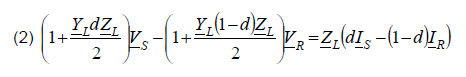
The coefficients at the measured voltage Vs, VR in (2) are different and depend on the distance to fault d. However replacing them by their average value results in:
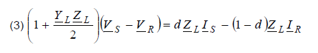
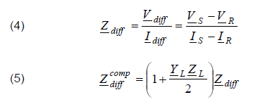
The differential impedance and the compensated differential impedance are introduced as follows:
Now the locational differential impedance is defined as:

Taking into account (4)-(6) one can obtain that the locational differential impedance is the following function of the sought distance to fault:
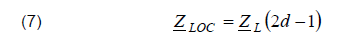
Therefore the fault location can be performed using
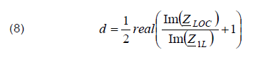
At the right-hand side of (8) the real part is taken to reject some imaginary part which can appear due to the calculation errors.
Impedance-differential protection – formulation for three phase system
For the purpose of paper conciseness only calculations of asymmetrical faults are demonstrated here, while the symmetrical faults consideration are presents in [7].
Differential impedance regarding asymmetrical faults can be determined using the symmetrical components. For calculation, in this paper, single-phase-to-earth fault is applied. Figure 2 represents the positive-, negative-, and zero-sequence network for a single phase-to-earth fault.
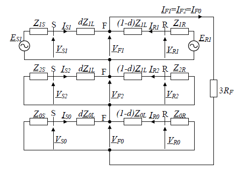
From Figure 2 following relationships can be observed:

Considering that the fault occurs in phase L1, and after implementation of symmetrical component properties, it can be obtained from (9):
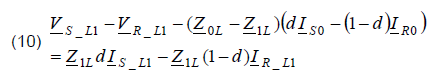
In view of zero sequence circuit presented in Figure 2, the voltage drop can be formulated as:
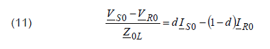
After substituting (11) to (10), the following formula is obtained:
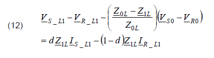
The formula (12) is analogous to (3) which was obtained for a single phase system. Therefore, taking this analogy, one can extend usage of the set of equations (4)-(8) to the single phase fault (L1–E) in three-phase system by taking:
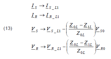
Analogous substitutions one has to apply for the remaining single phase faults (L2–E, L3–E). Moreover, this can be applied for phase1-phase2 and phase1-phase2-earth faults as well.
Data of simulated system
For evaluation of the presented protection algorithm, the model of the 400 kV double fed transmission line (Tab. 1) has been tested. The simulation was performed using the ATPDraw [13], while protection algorithm was implemented in MATLAB software. The phasors of measured currents and voltages were determined by the full-cycle Fourier filtering.
Table 1. Parameters of the modeled transmission line
Fault resistance influence
Length of the investigated line varied, and was equal to the following values: 80 km, 200 km and 300 km. However, for the sake of briefness, only results for 300 km line are shown in this paper. In order to test the proposed protection algorithm, short-circuit simulations were conducted inside the line as well as beyond it. The inner faults were simulated, referring to the S side at distances of d = 0; 0.1; 0.2; 0.3;…1. The faults applied outside the protected line, were located behind the terminals S and R, respectively. The studies included symmetrical faults (three-phase-to-earth faults) and different asymmetrical faults (phase-to-earth (L1-E), phase-to-phase (L1-L2), and phase-to-phase-to-earth (L1-L2-E) faults).
The presented fault location algorithm was compared with the two-end synchronized fault location algorithms (14) presented in [2]
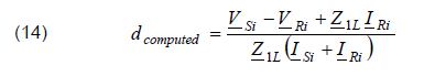
where i – kind of processed signals.
The error of studied impedance-differential algorithm was defined as

The presented results in Table 2 and 3 concern phase-to-earth (L1-E) faults inside the protected line, regarding to the fault resistance. The results included phase-to-phase faults are presented in Table 4. The fault location errors were determined as follows:
• errorDIFF – use of signals of impedance-differential protection
• errorDIFF0 – as for errorDIFF but without shunt capacitances compensation
• error1 – use of positive sequence component
• error2 – use of negative sequence component
• errorL1-E – use of signals applied in distance protection for L1-E fault
• errorL1-L2 – use of signals applied in distance protection for L1-L2 fault.
It is visible that fault location computation concerning compensation were more accurate than neglecting it. Maximal error obtained by the presented algorithm (with compensation) did not exceed 0.8% while without compensation this value was insignificantly higher than 1%. In contrast, the result calculated in case of positive sequence component based location algorithm was even greater than 4%.
Additionally, for phase-to-phase faults, the average error computed for considered protection method was equaled to 0.0904% (with compensation) and it means that from all used methods this calculated faults location the most accurately. On the contrary, the average error calculated for negative sequence based algorithm was the highest in case of the faults simulated for fault resistance amount to 2 Ω.
Table 2. Fault location error, L1-E fault, RF = 10 Ω
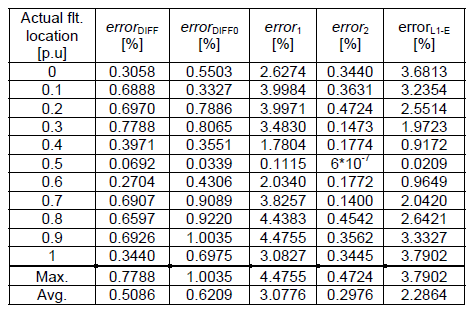
Generally, the differential impedance algorithm enabled to locate faults with maximal average error equaled to 0.5086%. Only algorithm based on negative sequence components worked more accurate, and the maximal average error did not exceed 0.3418%. However, taken into consideration all average error results, differential impedance protection method was the most precise from all of compared algorithms in except of the simulation made for L1-E fault with RF=10 Ω.
Table 3. Fault location error, L1-E fault, RF=50 Ω

Table 4. Fault location error, L1-L2 fault, RF = 2 Ω

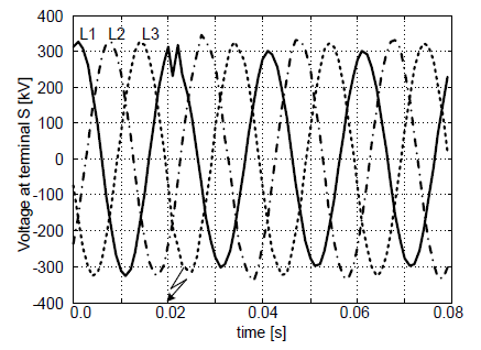
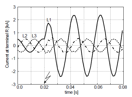
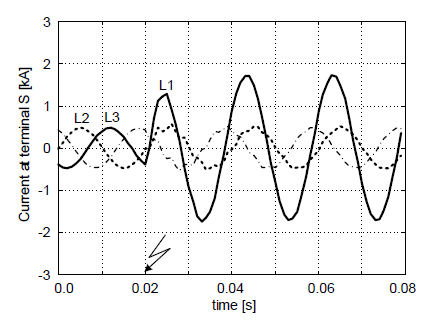
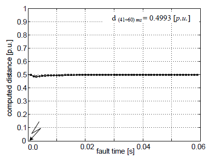
The sample example is presented in Figure 3 – 7. The specifications of it are as follows: phase-to-earth (L1-E) fault at the midpoint of 300 km line, RF=10 Ω. The computed fault location is depicted in Figure 7 where d(41÷60)ms was obtained by averaging within the interval (41÷60) ms after the fault inception.

While simulating short-circuits in the middle of the protected line, it was observed that independently of the applied fault location algorithm, the computed distances were characterized by the smallest error. This situation was observed for all fault types.
As presented in Tables 2 – 4, the considered protection algorithm allows to detect faults in all conditions, regardless of different fault types and fault resistance.
Conclusions
The aim of this paper is to present the concept of impedance-differential protection for long transmission lines. The demonstrated protection algorithm enables not only for internal fault detection, but can be applied also as a fault locator.
Based on simulation results it can be concluded that presented method can be used for transmission lines with different lengths as well as is not influenced by the fault resistance changes.
Moreover, capacitive charging current which constitutes the main drawback of current differential protection is eliminated in presented protection method and does not influence on the fault location determination.
In addition, the accuracy of fault location achieved in case of impedance-differential relay allows to improve the faults location calculation obtained from the use of two-end synchronized fault location algorithms. The precision of presented algorithm is on the same level as for method using negative sequence components and even has superiority over it, in case of phase-to-phase faults (L1-L2 faults, Tab. 4).
The obtained results approve the high reliability of the impedance-differential protection.
For the further studies of demonstrated protection algorithm as a transmission line fault locator, the impact of source strength or shunt reactors application could be evaluated.
REFERENCES
[1] Kacejko P., Machowski J., Zwarcia w systemach elektroenergetycznych, WNT Warszawa (2002)
[2] Saha M.M., Izykowski J., Rosolowski E., Fault Location on Power Networks, Springer, London (2010)
[3] Halinka A., Szewczyk M., Talaga M., Metodyka pomiarów synchronicznych (PMU) oraz przykłady zastosowania. Wiadomości Elektrotechniczne, 82 (2014), no 8, 21-25
[4] Iżykowski J., Rosołowski E., Synchroniczne pomiary rozproszone w zastosowaniu do lokalizacji zwarć w liniach napowietrznych, Przegląd Eektrotechniczny, 85 (2009), no. 11, 21-25
[5] Szewczyk M., Time synchronization for synchronous measurements in Electric Power Systems with reference to the IEEE C37.118TM Standard – selected tests and recommendations, Przegląd Elektrotechniczny, 91 (2015), no. 4, 144–148
[6] Altuve Ferrer H.J., Kasztenny B., Fischer N., Line current differential protection, A collection of technical papers representing modern solutions, Schweitzer Engineering Laboratories, (2014)
[7] Ghanizade Bolandi T., Seyedi H., Hasemi S.M., Soleiman Nezhad P., Impedance-differential protection: A new approach to transmission-line pilot protection, IEEE Transaction on power delivery, 30 (2015), no. 6, 2510-2518
[8] Suonan J.L., Deng X.Y., Liu K., Transmission line pilot protection principle based on integrated impedance, IET Trans. Distrib. Gen., 5 (2011), no. 10, 1003–1010
[9] Kowalik R., Rasolomampionona D., Glik K., Detection, classification and fault location in HV lines using travelling waves, Przegląd Elektrotechninczy, 88 (2012), no. 1a, 269-275
[10] Wiszniewski A., Dokładna lokalizacja miejsca zwarcia w liniach napowietrznych elektroenergetycznych, Przegląd Elektrotechniczny, 60 (1984), no. 2, 41-44
[11] Smolarczyk A., Szweicer W., Porównanie wybranych metod lokalizacji miejsca zwarcia, Przegląd Elektrotechniczny, 79 (2003), no.2, 59-64
[12] Iżykowski J., Saha M., Rosołowski E., Wykorzystanie prądów wejściowych zabezpieczeniowych przekaźników różnicowych do lokalizacji zwarć, Przegląd Elektrotechniczny, 84 (2008), no.5, 9-13
[13] Dommel H., ElectroMagnetic Transients Program, BPA, Portland, Oregon, (1986)
Authors: MSc. Justyna Herlender, prof. dr. Jan Iżykowski, prof. dr. Eugeniusz Rosołowski, Wroclaw University of Science and Technology, Department of Electrical Power Engineering, 27 Wybrzeże Wyspiańskiego St., 50-370 Wroclaw, Poland; E-mails: justyna.herlender@pwr.edu.pl, jan.izykowski@pwr.edu.pl; eugeniusz.rosolowski@pwr.edu.pl
Source & Publisher Item Identifier: PRZEGLĄD ELEKTROTECHNICZNY, ISSN 0033-2097, R. 93 NR 11/2017. doi:10.15199/48.2017.11.40
